
2017 PATRIOT USER GUIDE
Jeep.com (U.S.) Jeep.ca (Canada)
DOWNLOAD A FREE ELECTRONIC COPY of the
Owner’s Manual and Warranty Booklet by visiting:
www.jeep.com/en/owners/manuals or
www.jeep.com/en/warranty (U.S.);
www.owners.mopar.ca/en (Canada).
©2016 FCA US LLC. All Rights Reserved.
Jeep is a registered trademark of FCA US LLC.
Whether it’s providing
information about specific
product features, taking a
tour through your vehicle’s
heritage, knowing what
steps to take following an accident,
or scheduling your next appointment,
we know you’ll find the app an
important extension of your Jeep
brand vehicle. Simply download the
app, select your make and model and
enjoy the ride. To get this app, go
directly to the App Store or Google
Play and enter the search keyword
“JEEP” (U.S. market only).
jeep.com /en /owners provides
special oers tailored to your
needs, customized vehicle galleries,
personalized service records and
more. To get this information, just
create an account and check
back often.
17MK74-926-AA
Patriot
Third Edition
User Guide
2667646_17c_Patriot_UG_082616.indd 1 8/26/16 2:07 PM

If you are the first registered retail
owner of your vehicle, you may
obtain a complimentary printed copy
of the Owner’s Manual, Navigation/
Uconnect Manuals or Warranty
Booklets by calling 1 877 426-5337
(U.S.) or 1 800 387-1143 (Canada)
or by contacting your dealer.
The driver’s primary responsibility is
the safe operation of the vehicle.
Driving while distracted can result in
loss of vehicle control, resulting in a
collision and personal injury. FCA US
LLC strongly recommends that the
driver use extreme caution when
using any device or feature that may
take their attention o the road.
Use of any electrical devices, such
as cellular telephones, computers,
portable radios, vehicle navigation
or other devices, by the driver
while the vehicle is moving is
dangerous and could lead to a
serious collision. Texting while
driving is also dangerous and
should never be done while the
vehicle is moving.
If you find yourself unable to
devote your full attention to vehicle
operation, pull o the road to a
safe location and stop your vehicle.
Some states or provinces prohibit
the use of cellular telephones or
texting while driving. It is always
the driver’s responsibility to comply
with all local laws.
Important:
This User Guide is intended to familiarize you with the
important features of your vehicle. Your Owner’s Manual,
Navigation/Uconnect Manuals and Warranty Booklets can be
found on your DVD (if applicable) or by visiting the website
on the back cover of your User Guide. We hope you find it
useful. U.S. residents can purchase replacement DVD kits by
visiting www.techauthority.com and Canadian residents can
purchase replacement DVD kits by calling 1 800 387-1143.
This guide has been prepared to help you
get quickly acquainted with your new Jeep
brand vehicle and to provide a convenient
reference source for common questions.
However, it is not a substitute for your
Owner’s Manual.
For complete operational instructions,
maintenance procedures and important
safety messages, please consult your
Owner’s Manual, Navigation/Uconnect
manuals found on the website on the back
cover and other Warning Labels
in your vehicle.
Not all features shown in this guide
may apply to your vehicle. For additional
information on accessories to help
personalize your vehicle, visit
www.mopar.com (U.S.), www.mopar.ca
(Canada) or your local Jeep brand dealer.
Driving and Alcohol:
Drunken driving is one of the most frequent causes of collisions. Your
driving ability can be seriously impaired with blood alcohol levels far below
the legal minimum. If you are drinking, don’t drive. Ride with a designated
non-drinking driver, call a cab, a friend, or use public transportation.
WARNING!
Driving after drinking can lead to a collision. Your perceptions are less
sharp, your reflexes are slower, and your judgment is impaired when you
have been drinking. Never drink and then drive.
2667646_17c_Patriot_UG_082616.indd 2 8/26/16 2:07 PM

Congratulations on selecting your new FCA
US LLC (“FCA US”) vehicle. Be assured that
it represents precision workmanship, distinc-
tive styling, and high quality.
Your new FCA US LLC vehicle has character-
istics to enhance the driver's control under
some driving conditions. These are to assist
the driver and are never a substitute for
attentive driving. They can never take the
driver's place. Always drive carefully.
Your new vehicle has many features for the
comfort and convenience of you and your
passengers. Some of these should not be
used when driving because they take your
eyes from the road or your attention from
driving. Never text while driving, or more than
momentarily take your eyes off the road.
This guide illustrates and describes the op-
eration of features and equipment that are
either standard or optional on this vehicle.
This guide may also include a description of
features and equipment that are no longer
available or were not ordered on this vehicle.
Please disregard any features and equipment
described in this guide that are not available
on this vehicle. FCA US reserves the right to
make changes in design and specifications
and/or make additions to or improvements to
its products without imposing any obligation
upon itself to install them on products previ-
ously manufactured.
This User Guide has been prepared to help
you quickly become acquainted with the im-
portant features of your vehicle. It contains
most things you will need to operate and
maintain the vehicle, including emergency
information.
For complete owner information, refer to your
Owner's Manual at
www.jeep.com/en/owners/manuals/ for further
details. For your convenience, the informa-
tion contained on this site may also be
printed and saved for future reference.
FCA US LLC is committed to protecting our
environment and natural resources. By con-
verting from paper to electronic delivery for
the majority of the user information for your
vehicle, together we greatly reduce the de-
mand for tree-based products and lessen the
stress on our environment.
When it comes to service, remember that your
authorized dealer knows your Jeep
®
vehicle
best, has factory-trained technicians and
genuine MOPAR
®
parts, and cares about your
satisfaction.
WELCOME FROM FCA US LLC
1

HOW TO USE THIS MANUAL
Essential Information
Each time direction instructions (left/right or
forwards/backwards) about the vehicle are
given, these must be intended as regarding
an occupant in the driver's seat. Special
cases not complying with this rule will be
properly specified in the text.
The figures in the Owner Handbook are pro-
vided by way of example only: this might
imply that some details of the image do not
correspond to the actual arrangement of your
vehicle.
In addition, the Handbook has been con-
ceived considering vehicles with steering
wheel on the left side; it is therefore possible
that on vehicles with steering wheel on the
right side, the position or construction of
some controls is not exactly mirror-like with
respect to the figure.
To identify the chapter with the information
needed you can consult the index at the end
of this Owner Handbook.
Chapters can be rapidly identified with dedi-
cated graphic tabs, at the side of each odd
page. A few pages further there is a key for
getting to know the chapter order and the
relevant symbols in the tabs. There is anyway
a textual indication of the current chapter at
the side of each even page.
Symbols
Some vehicle components have colored la-
bels whose symbols indicate precautions to
be observed when using this component.
ROLLOVER WARNING
Utility vehicles have a significantly higher
rollover rate than other types of vehicles. This
vehicle has a higher ground clearance and a
higher center of gravity than many passenger
vehicles. It is capable of performing better in
a wide variety of off-road applications. Driven
in an unsafe manner, all vehicles can go out
of control. Because of the higher center of
gravity, if this vehicle is out of control it may
roll over while some other vehicles may not.
Do not attempt sharp turns, abrupt maneu-
vers, or other unsafe driving actions that can
cause loss of vehicle control. Failure to oper-
ate this vehicle safely may result in a colli-
sion, rollover of the vehicle, and severe or
fatal injury. Drive carefully.
Failure to use the driver and passenger seat
belts provided is a major cause of severe or
fatal injury. In fact, the U.S. government
notes that the universal use of existing seat
belts could cut the highway death toll by
10,000 or more each year and could reduce
disabling injuries by two million annually. In
a rollover crash, an unbelted person is signifi-
cantly more likely to die than a person wear-
ing a seat belt. Always buckle up.
Rollover Warning Label
HOW TO USE THIS MANUAL
2

WARNINGS AND CAUTIONS
While reading this Owner Handbook you will
find a series of WARNINGS to prevent proce-
dures that could damage your vehicle.
There are also CAUTIONS that must be care-
fully followed to prevent incorrect use of the
components of the vehicle, which could
cause accidents or injuries.
VEHICLE CHANGES/
ALTERATIONS
IMPORTANT: Any change or alteration of the
vehicle might seriously affect its safety and
road holding, thus causing accidents, in
which the occupants could even be fatally
injured.
HOW TO USE THIS MANUAL
3

4

GRAPHICAL TABLE OF CONTENTS
GETTING TO KNOW YOUR VEHICLE
GETTING TO KNOW YOUR INSTRUMENT PANEL
SAFETY
STARTING AND OPERATING
IN CASE OF EMERGENCY
SERVICING AND MAINTENANCE
TECHNICAL SPECIFICATIONS
MULTIMEDIA
CUSTOMER ASSISTANCE
INDEX

6

GRAPHICAL TABLE OF CONTENTS
INSTRUMENT PANEL...........8
INTERIOR...................9
GRAPHICAL TABLE OF CONTENTS
7

INSTRUMENT PANEL
Instrument Panel
1 — Door Handle 5 — Climate Controls 9 — Gear Selector 13 — Multifunction Lever
2 — Air Outlets 6 — Glove Compartment 10 — Ignition Switch
3 — Instrument Cluster 7 — Window Switch 11 — Horn/Driver Air Bag
4 — Radio 8 — Seats 12 — Instrument Cluster Display
Controls
GRAPHICAL TABLE OF CONTENTS
8

INTERIOR
Interior Features
1 — Air Outlet
2 — Instrument Cluster
3 — Glove Compartment
4 — Ignition Switch
5 — Horn/Driver Air Bag
6 — Multifunction Lever
9

10

GETTING TO KNOW YOUR VEHICLE
KEYS .....................13
A Word About Your Keys ..........13
Locking Doors With A Key .........13
To Unlock The Doors And Liftgate .....13
IGNITIONSWITCH............13
Ignition Key Removal ............13
Key Fob-In-Ignition Reminder .......14
REMOTE STARTING SYSTEM — IF
EQUIPPED .................15
To Enter Remote Start ............15
VEHICLE SECURITY ALARM — IF
EQUIPPED..................15
To Arm The System ..............15
To Disarm The System ............16
Vehicle Security Alarm Manual Override .16
DOOR LOCKS ...............16
Manual Door Locks ..............16
Power Door Locks ..............17
Child-Protection Door Lock System — Rear
Doors ......................17
SEATS ....................18
Manual Seats .................18
Power Seats ..................20
Heated Seats..................20
Folding Rear Seat ..............21
Reclining Rear Seat .............22
HEADRESTRAINTS...........22
Supplemental Active Head Restraints —
Front Seats ..................22
Rear Head Restraints.............24
STEERING WHEEL ...........24
Tilt Steering Column .............24
MIRRORS ..................25
Interior Mirrors ................25
Exterior Mirrors ................26
EXTERIORLIGHTS ...........26
Headlights And Parking Lights .......26
Daytime Running Lights — If Equipped
. .26
High/Low Beam Switch ...........27
Flash-To-Pass .................27
Automatic Headlights ............27
Fog Lights ...................27
Turn Signals ..................27
Lights-On Reminder .............28
Headlights On With Wipers (Available With
Automatic Headlights Only) ........28
INTERIORLIGHTS............28
Instrument Panel Dimming .........28
Map/Reading Lights .............28
WINDSHIELD WIPERS AND
WASHERS .................29
Windshield Wiper Operation.........29
Intermittent Wiper System .........29
Windshield Washers .............30
Headlights On With Wipers (Available With
Automatic Headlights Only) ........30
Mist Feature ..................30
Rear Window Wiper/Washer ........31
CLIMATECONTROLS..........31
Manual Climate Controls...........31
Automatic Climate Controls .........34
Automatic Temperature Control (ATC) — If
Equipped ....................38
Operating Tips .................40
GETTING TO KNOW YOUR VEHICLE
11

POWER WINDOWS — IF
EQUIPPED .................42
Power Window Switches ...........42
Auto-Down ...................42
Window Lockout Switch ...........43
POWER SUNROOF ...........43
Opening.....................44
Closing .....................44
Wind Buffeting ................44
Sunshade Operation .............44
Pinch Protect Feature ............45
Sunroof Maintenance.............45
Ignition Off Operation ............45
TO OPEN AND CLOSE THE
HOOD .....................45
LIFTGATE .................46
Cargo Area Features .............47
UNIVERSAL GARAGE DOOR
OPENER (HomeLink) .........48
Before You Begin Programming
HomeLink ...................48
Programming A Rolling Code ........49
Programming A Non-Rolling Code .....49
Using HomeLink ...............50
INTERNAL EQUIPMENT........50
Power Outlet .................50
Power Inverter ................52
GETTING TO KNOW YOUR VEHICLE
12
KEYS
Your vehicle uses a keyless ignition system.
The ignition system consists of a key fob with
Remote Keyless Entry (RKE) and a START/
STOP push button ignition system. The Re-
mote Keyless Entry system consists of a key
fob and Keyless Enter-N-Go feature.
NOTE:
The passive entry key fob if left inside the car
may not be found by the passive entry control
module if it is located next to a cell phone,
laptop, or other electronic devices, since they
could block the frequency signal.
A Word About Your Keys
The authorized dealer that sold you your new
vehicle has the key code numbers for your
vehicle locks. These numbers can be used to
order duplicate Remote Keyless Entry (RKE)
key fobs. Ask your authorized dealer for these
numbers and keep them in a safe place.
Locking Doors With A Key
You can insert the key with either side up. To
lock the door, turn the key to the right. To
unlock the door, turn the key to the left. Refer
to ”Body Lubrication” in Dealer Service” in
“Servicing And Maintenance” for further in-
formation.
To Unlock The Doors And Liftgate
Push and release the unlock button on the
key fob once to unlock the driver’s door or
twice within five seconds to unlock all doors
and liftgate. The turn signal lights will flash
to acknowledge the unlock signal. The illumi-
nated entry system will also turn on.
IGNITION SWITCH
Ignition Key Removal
1. Place the gear selector in PARK (if
equipped with an automatic
transmission).
2. Place the ignition in the ACC (Accessory)
position.
3. Push the key and cylinder inward and
rotate the key to the LOCK position.
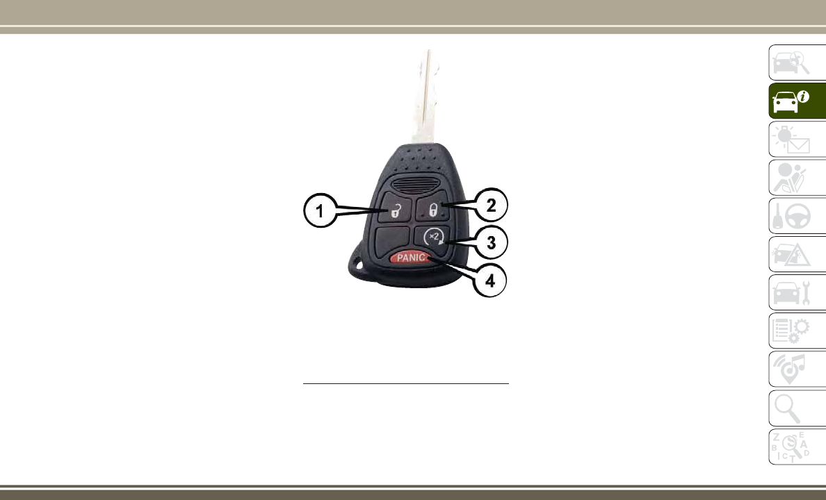
Key Fob
1 — Unlock
2 — Lock
3 — Remote Start
4 — Panic
13

4. Remove the key from the ignition. NOTE:
If you try to remove the key before you place
the gear selector in PARK, the key may be-
come trapped temporarily in the ignition. If
this occurs, place the gear selector in PARK,
rotate the key clockwise slightly, and then
remove the key as described above. If a
malfunction occurs, the system will trap the
key in the ignition to warn you that this safety
feature is inoperable. The engine can be
started and stopped but the key cannot be
removed until you obtain service.
WARNING!
• Before exiting a vehicle, always shift the
automatic transmission into PARK or the
manual transmission into FIRST gear or
REVERSE, apply the parking brake, turn
the engine OFF, remove the key fob from
the ignition and lock your vehicle.
• Never leave children alone in a vehicle,
or with access to an unlocked vehicle.
• Allowing children to be in a vehicle un-
attended is dangerous for a number of
reasons. A child or others could be seri-
ously or fatally injured. Children should
WARNING!
be warned not to touch the parking
brake, brake pedal or the gear selector.
• Do not leave the key fob in or near the
vehicle, or in a location accessible to
children. A child could operate power
windows, other controls, or move the
vehicle.
• Do not leave children or animals inside
parked vehicles in hot weather. Interior
heat build-up may cause serious injury
or death.
CAUTION!
Always remove the key fobs from the ve-
hicle and lock all doors when leaving the
vehicle unattended.
Key Fob-In-Ignition Reminder
Opening the driver's door when the key is in
the ignition and the ignition position is LOCK
or ACC sounds a signal to remind you to
remove the key.
Ignition Switch
GETTING TO KNOW YOUR VEHICLE
14

NOTE:
With the driver's door open and the key in the
ignition, the power door locks will not lock,
and key fob will not function.
REMOTE STARTING
SYSTEM — IF EQUIPPED
This system uses the key fob to remote start
the engine conveniently from outside the ve-
hicle, while still maintaining security. The
system has a range of approximately 328 ft
(100 m). Obstructions between the vehicle
and key fob may reduce this range.
NOTE:
• The vehicle must be equipped with an
automatic transmission to be equipped
with Remote Start.
• Obstructions between the vehicle and the
key fob may reduce this range.
To Enter Remote Start
Push and release the Remote Start button on
the key fob twice within five seconds. The
vehicle doors will lock, the parking lights will
flash, and the horn will chirp twice (if pro-
grammed). Then, the engine will start and the
vehicle will remain in the Remote Start mode
for a 15-minute cycle.
NOTE:
• The park lamps will turn on and remain on
during Remote Start mode.
• For security, power window and power sun-
roof operation (if equipped) are disabled
when the vehicle is in the Remote Start
mode.
• If your power door locks were unlocked,
Remote Start will automatically lock the
doors.
• The engine can be started two consecutive
times (two 15-minute cycles) with the key
fob. However, the ignition must be placed
in the ON/RUN position before you can
repeat the start sequence for a third cycle.
Remote Start will also cancel if any of the
following occur:
• The engine stalls or RPM exceeds 2500.
• Any engine warning lamps come on.
• Low Fuel Light turns on.
• The hood is opened.
• The hazard switch is pushed.
• The transmission is moved out of PARK.
• The brake pedal is pushed.
VEHICLE SECURITY ALARM
— IF EQUIPPED
This vehicle security alarm monitors the
doors, liftgate, and ignition switch for unau-
thorized operation.
When the alarm is activated, the interior
switches for door locks are disabled. The
vehicle security alarm provides both audio
and visual signals, the horn will sound, the
headlights, park lamps and/or turn signals
will flash repeatedly for three minutes. If the
disturbance is still present (driver's door, pas-
senger door, other doors, ignition) after three
minutes, the parking lights and tail lights will
flash for an additional 15 minutes.
To Arm The System
1. Remove the key fob from the ignition and
get out of the vehicle.
15

2. Lock the door using either the power door
lock switch or the key fob lock button and
close all doors.
3. The vehicle security light in the instru-
ment cluster will flash rapidly for approxi-
mately 16 seconds. This shows that the
vehicle security alarm is arming. During
this period, if a door is opened, the igni-
tion is placed in the ON/RUN position, or
the power door locks are unlocked in any
manner, the vehicle security alarm will
automatically disarm. After approximately
16 seconds, the vehicle security light will
flash slowly. This shows that the vehicle
security alarm is fully armed.
To Disarm The System
Push unlock on the key fob, or insert the key
into the ignition and place the ignition in the
ON/RUN position.
If something has triggered the vehicle secu-
rity alarm in your absence, the horn will
sound three times, and exterior lights blink
three times when you unlock the doors.
Check the vehicle for tampering. The vehicle
security alarm is designed to protect your
vehicle. However, you can create conditions
where the vehicle security alarm will arm
unexpectedly. If you remain in the vehicle
and lock the doors with the key fob, once the
vehicle security alarm is armed (after 16 sec-
onds), when you pull the door handle to exit,
the alarm will sound. If this occurs, push the
unlock button on the key fob to disarm the
vehicle security alarm.
Vehicle Security Alarm Manual Override
The vehicle security alarm will not arm if you
lock the doors using the manual door lock
plunger.
DOOR LOCKS
Manual Door Locks
Use the manual door lock knob to lock the
doors from inside the vehicle. If the lock knob
is down when the door is closed, the door will
lock. Make sure the keys are not inside the
vehicle before closing the door.
WARNING!
• For personal security and safety in the
event of an collision, lock the vehicle
doors as you drive as well as when you
park and leave the vehicle.
• Never leave children alone in a vehicle,
or with access to an unlocked vehicle.
Allowing children to be in a vehicle un-
attended is dangerous for a number of
Manual Door Lock Knob
GETTING TO KNOW YOUR VEHICLE
16
WARNING!
reasons. A child or others could be seri-
ously or fatally injured. Children should
be warned not to touch the parking
brake, brake pedal or the gear selector.
• Do not leave the key fob in or near the
vehicle, or in a location accessible to
children. A child could operate power
windows, other controls, or move the
vehicle.
CAUTION!
Always remove the key fobs from the ve-
hicle and lock all doors when leaving the
vehicle unattended.
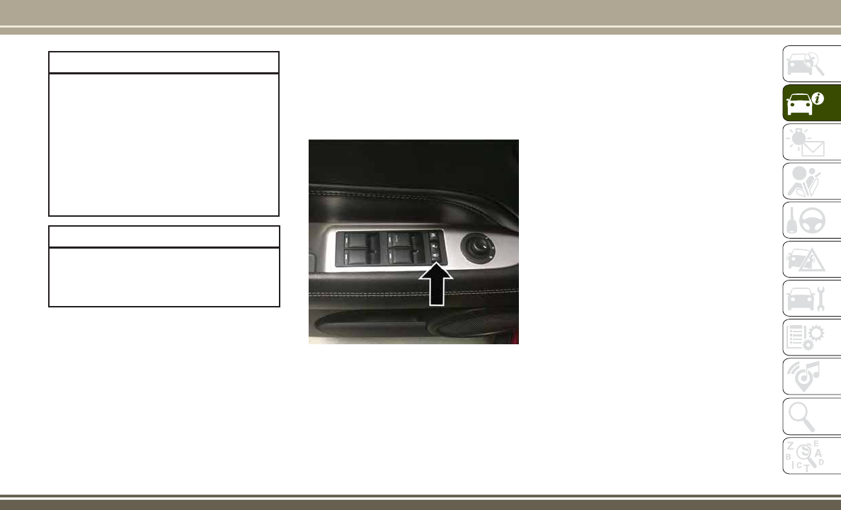
Power Door Locks
A power door lock switch is located on the
driver's and front passenger's door panel.
Push these switches to lock or unlock the
doors and liftgate.
NOTE:
To prevent from locking the key in the vehicle,
the power door lock switch will not operate
when the key is in the ignition and either front
door is open. A chime will sound as a re-
minder to remove the key.
Auto Lock Doors — If Equipped
The Automatic Door Lock feature default con-
dition is enabled. When enabled, the door
locks will lock automatically when the vehi-
cle's speed exceeds 15 mph (24 km/h).
Child-Protection Door Lock System —
Rear Doors
To provide a safer environment for small chil-
dren riding in the rear seats, the rear doors
are equipped with Child-Protection Door
Lock system.
To Engage Or Disengage The Child-
Protection Door Lock System
1. Open the rear door.
2. Insert the tip of the ignition key into the
lock and rotate to the lock or unlock
position.
Driver Power Door Lock Switch
17

3. Repeat steps 1 and 2 for the opposite rear
door.
WARNING!
Avoid trapping anyone in a vehicle in a
collision. Remember that the rear doors
can only be opened from the outside when
the Child-Protection locks are engaged.
NOTE:
For emergency exit with the system engaged,
move the lock knob up (unlocked position),
roll down the window, and open the door with
the outside door handle.
SEATS
Seats are a part of the Occupant Restraint
System of the vehicle.
WARNING!
• It is dangerous to ride in a cargo area,
inside or outside of a vehicle. In a colli-
sion, people riding in these areas are
more likely to be seriously injured or
killed.
• Do not allow people to ride in any area of
your vehicle that is not equipped with
seats and seat belts. In a collision,
people riding in these areas are more
likely to be seriously injured or killed.
• Be sure everyone in your vehicle is in a
seat and using a seat belt properly.
Manual Seats
Manual Front Seat Adjustment
On models equipped with manual seats, the
adjusting bar is located at the front of the
seats, near the floor. While sitting in the seat,
lift up on the bar and move the seat forward or
rearward. Release the bar once you have
reached the desired position. Then, using
body pressure, move forward and rearward on
the seat to be sure that the seat adjusters
have latched.
Child-Protection Door Lock Location
Manual Seat Adjusting Bar
GETTING TO KNOW YOUR VEHICLE
18

WARNING!
• Adjusting a seat while driving may be
dangerous. Moving a seat while driving
could result in loss of control which
could cause a collision and serious in-
jury or death.
• Seats should be adjusted before fasten-
ing the seat belts and while the vehicle
is parked. Serious injury or death could
result from a poorly adjusted seat belt.
Manual Seat Height Adjustment
The driver's seat height can be raised or
lowered by using a lever, located on the
outboard side of the seat. Pull upward on the
lever to raise the seat height or push down-
ward on the lever to lower the seat height.
Manual Lumbar
The lumbar adjustment handle is located on
the inboard or outboard side of the seatback.
Rotate the lever downward to increase the
lumbar support or rotate the lever upward to
decrease the lumbar support.
Driver's Seatback Recline
To adjust the seatback, lift the lever located
on the outboard side of the seat, lean back to
the desired angle and release the lever. To
return the seatback, lift the lever, lean for-
ward and release the lever.
WARNING!
Do not ride with the seatback reclined so
that the shoulder belt is no longer resting
against your chest. In a collision you could
slide under the seat belt, which could
result in serious injury or death.
Lumbar Support Lever
19

Power Seats
Some models may be equipped with a power
driver’s seat. The power seat switch is located
on the outboard side of the seat near the
floor. Use the switch to move the seat up,
down, forward, rearward, or to tilt the seat.
WARNING!
• Adjusting a seat while driving may be
dangerous. Moving a seat while driving
could result in loss of control which
could cause a collision and serious in-
jury or death.
• Seats should be adjusted before fasten-
ing the seat belts and while the vehicle
is parked. Serious injury or death could
result from a poorly adjusted seat belt.
CAUTION!
Do not place any article under a power seat
or impede its ability to move as it may
cause damage to the seat controls. Seat
travel may become limited if movement is
stopped by an obstruction in the seat’s
path.
Adjusting The Seat Forward Or Rearward
The seat can be adjusted both forward and
rearward. Push the seat switch forward or
rearward. The seat will move in the direction
of the switch. Release the switch when the
desired position has been reached.
Adjusting The Seat Up Or Down
The height of the seats can be adjusted up or
down. Pull upward or push downward on the
seat switch. The seat will move in the direc-
tion of the switch. Release the switch when
the desired position is reached.
Tilting The Seat Up Or Down
The angle of the seat cushion can be adjusted
in four directions. Pull upward or push down-
ward on the front or rear of the seat switch,
the front or rear of the seat cushion will move
in the direction of the switch. Release the
switch when the desired position is reached.
Heated Seats
On some models, the front driver and passen-
ger seats may be equipped with heaters in
both the seat cushions and seatbacks. The
controls for the front heated seats are located
on the center instrument panel area.
You can choose from HI, LO or OFF heat
settings. Amber indicator lights in each
switch indicate the level of heat in use. Two
indicator lights will illuminate for HI, one for
LO and none for OFF.
Power Seat Switch
GETTING TO KNOW YOUR VEHICLE
20

Push the switch once to select HI-level heat-
ing. Push the switch a second time to select
LO-level heating. Push the switch a third time
to shut the heating elements OFF.
When the HI-level setting is selected, the
heater will provide a boosted heat level dur-
ing the initial stages of operation. Then, the
heat output will drop to the normal HI-level.
If the HI-level setting is selected, the system
will automatically switch to LO-level after
approximately 30 minutes of continuous op-
eration. At that time, the display will change
from HI to LO, indicating the change. When
the LO-level heating is selected, the system
automatically turns the heater and the indi-
cator light OFF after approximately 30 min-
utes of continuous operation.
NOTE:
Once a heat setting is selected, heat will be
felt within two to five minutes.
WARNING!
• Persons who are unable to feel pain to
the skin because of advanced age,
chronic illness, diabetes, spinal cord in-
jury, medication, alcohol use, exhaus-
tion or other physical condition must
exercise care when using the seat
heater. It may cause burns even at low
temperatures, especially if used for long
periods of time.
• Do not place anything on the seat or
seatback that insulates against heat,
such as a blanket or cushion. This may
cause the seat heater to overheat. Sit-
ting in a seat that has been overheated
WARNING!
could cause serious burns due to the
increased surface temperature of the
seat.
Folding Rear Seat
To provide additional storage area, each rear
seatback can be folded forward. Pull the
strap forward to fold the rear seatback flat.
NOTE:
You may experience deformation in the seat
cushion from the seat belt buckles if the
seats are left folded for an extended period of
time. This is normal and by simply opening
the seats to the open position, over time the
seat cushion will return to its normal shape.
To raise the seatback, pull the strap forward
and lift the seatback into its upright position.
WARNING!
Be certain that the seatback is securely
locked into position. If the seatback is not
securely locked into position the seat will
Heated Seat Switches
21

WARNING!
not provide the proper stability for child
seats and/or passengers. An improperly
latched seat could cause serious injury.
Reclining Rear Seat
For additional comfort, pull the strap forward
just enough to release the seatback latch.
Then, push the seatback to a reclined posi-
tion, approximately 35 degrees maximum,
and release the strap.
WARNING!
Do not ride with the seatback reclined so
that the shoulder belt is no longer resting
against your chest. In a collision, you
could slide under the seat belt and be
seriously or even fatally injured. Use the
recliner only when the vehicle is parked.
HEAD RESTRAINTS
Head restraints are designed to reduce the
risk of injury by restricting head movement in
the event of a rear impact. Head restraints
should be adjusted so that the top of the head
restraint is located above the top of your ear.
WARNING!
• All occupants, including the driver,
should not operate a vehicle or sit in a
vehicle’s seat until the head restraints
are placed in their proper positions in
order to minimize the risk of neck injury
in the event of a crash.
• Head restraints should never be ad-
justed while the vehicle is in motion.
WARNING!
Driving a vehicle with the head restraints
improperly adjusted or removed could
cause serious injury or death in the
event of a collision.
Supplemental Active Head Restraints —
Front Seats
Active Head Restraints (AHRs) are passive,
deployable components, and vehicles with
this equipment cannot be readily identified
by any markings, only through visual inspec-
tion of the head restraint. The head restraint
will be split in two halves, with the front half
being soft foam and trim, the back half being
decorative plastic.
When AHRs deploy during a rear impact, the
front half of the head restraint extends for-
ward to minimize the gap between the back
of the occupant’s head and the AHR. This
system is designed to help prevent or reduce
the extent of injuries to the driver and front
passenger in certain types of rear impacts.
Refer to “Occupant Restraints” in “Safety”
for further information.
Rear Seat Release Strap
GETTING TO KNOW YOUR VEHICLE
22

To raise the head restraint, pull upward on the
head restraint. To lower the head restraint,
push the adjustment button located at the
base of the head restraint and push down-
ward on the head restraint.
For comfort, the Active Head Restraints can
be tilted forward and backward. To tilt the
head restraint closer to the back of your head,
pull forward on the bottom of the head re-
straint. Push rearward on the bottom of the
head restraint to move the head restraint
away from your head.
NOTE:
• The head restraints should only be re-
moved by qualified technicians, for ser-
vice purposes only. If either of the head
restraints require removal, see your autho-
rized dealer.
• In the event of deployment of an Active
Head Restraint, refer to “Occupant Re-
straints” in “Safety” for further
information.
Adjustment Button
Active Head Restraint (Normal Position)
Active Head Restraint (Tilted Position)
23

WARNING!
• All occupants, including the driver,
should not operate a vehicle or sit in a
vehicle’s seat until the head restraints
are placed in their proper positions in
order to minimize the risk of neck injury
in the event of a collision.
• Do not place items over the top of the
Active Head Restraint, such as coats,
seat covers or portable DVD players.
These items may interfere with the op-
eration of the Active Head Restraint in
the event of a collision and could result
in serious injury or death.
• Active Head Restraints may be deployed
if they are struck by an object such as a
hand, foot or loose cargo. To avoid acci-
dental deployment of the Active Head
Restraint ensure that all cargo is se-
cured, as loose cargo could contact the
Active Head Restraint during sudden
stops. Failure to follow this warning
could cause personal injury if the Active
Head Restraint is deployed.
Rear Head Restraints
The head restraints in the rear are non adjust-
able. Refer to “Occupant Restraints” in
“Safety” for information on Tether routing.
STEERING WHEEL
Tilt Steering Column
This feature allows you to tilt the steering
column upward or downward. The tilt steer-
ing column lever is located on the left side of
the steering column, below the turn signal
lever.
Push down on the lever to unlock the steering
column. With one hand firmly on the steering
wheel, move the steering column up or down,
as desired. Push the lever up to lock the
steering column firmly in place.
WARNING!
Do not adjust the steering column while
driving. Adjusting the steering column
while driving or driving with the steering
Rear Head Restraint
Steering Column Lever
GETTING TO KNOW YOUR VEHICLE
24

WARNING!
column unlocked, could cause the driver
to lose control of the vehicle. Failure to
follow this warning may result in serious
injury or death.
MIRRORS
Interior Mirrors
Inside Day/Night Mirror
A two-point pivot system allows for horizontal
and vertical mirror adjustment. Adjust the
mirror to center on the view through the rear
window.
Headlight glare can be reduced by moving
the small control under the mirror to the night
position (toward the rear of vehicle). The
mirror should be adjusted while set in the day
position (toward the windshield).
Automatic Dimming Mirror — If Equipped
This mirror automatically adjusts for head-
light glare from vehicles behind you. You can
turn the feature on or off by pushing the
button at the base of the mirror. The on/off
symbol on the button will illuminate when the
auto-dimming feature is enabled.
NOTE:
This feature is disabled when the vehicle is
moving in REVERSE.
CAUTION!
To avoid damage to the mirror during
cleaning, never spray any cleaning solu-
tion directly onto the mirror. Apply the
solution onto a clean cloth and wipe the
mirror clean.
Adjusting Rearview Mirror
Automatic Dimming Mirror
25
Exterior Mirrors
Power Mirrors
The power mirror control is located on the
driver’s door trim panel.
To adjust a mirror, turn the control wand
toward the left or right mirror positions indi-
cated. Tilt the control wand in the direction
you want the mirror to move.
When you are finished adjusting the mirror,
turn the control to the center position to
prevent accidentally moving a mirror.
Heated Mirrors — If Equipped
These mirrors are heated to melt frost or ice.
This feature is activated whenever you turn
on the rear window defroster. Refer to “Cli-
mate Controls” in “Getting To Know Your
Vehicle” for further information.
EXTERIOR LIGHTS
Headlights And Parking Lights
Turn the end of the multifunction lever to the
first detent to turn on the parking lights. Turn
the end of the lever to the second detent to
turn on the headlights.
Daytime Running Lights — If Equipped
The high beam lights will come on as Daytime
Running Lights (lower intensity) whenever
the ignition is ON, the engine is running, the
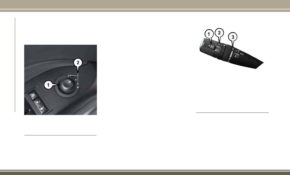
Power Mirror Controls
1 — Power Mirror Control
2 — Mirror Positions
Turn Signal/Lights Lever
1 — Fog Light Switch
2 — Headlight Switch
3 — Instrument Panel Dimmer
GETTING TO KNOW YOUR VEHICLE
26

headlight switch is off, the parking brake is
off, the turn signal is off and the gear selector
is in any position except PARK.
High/Low Beam Switch
Push the multifunction lever away from you
to switch the headlights to high beam. Pull
the multifunction lever toward you to switch
the headlights back to low beam.
Flash-To-Pass
You can signal another vehicle with your
headlights by lightly pulling the multifunc-
tion lever toward you. This will turn on the
high beam headlights until the lever is re-
leased.
NOTE:
If the multifunction lever is held in the flash-
to-pass position for more than 20 seconds,
the high beams will shut off. If this occurs,
wait 30 seconds for the next flash-to-pass
operation.
Automatic Headlights
Turning the end of the multifunction lever to
the third detent (AUTO), will activate the
automatic headlight system.
With the engine running and the multifunc-
tion lever in the AUTO position, the head-
lights will turn on and turn off based on the
surrounding light levels.
Fog Lights
The front fog light switch is on the multifunc-
tion lever. To activate the front fog lights, turn
on the parking lights or the low beam head-
lights and pull out the end of the multifunc-
tion lever.
NOTE:
The fog lights will only operate with the head-
lights on low beam. Selecting high beam
headlights will turn off the fog lights.
Turn Signals
Move the multifunction lever up or down and
the arrows on each side of the instrument
cluster flash to show proper operation of the
front and rear turn signal lights.
NOTE:
If either light remains on and does not flash,
or there is a very fast flash rate, check for a
defective outside light bulb. If an indicator
fails to light when the lever is moved, it would
suggest that the indicator bulb is defective.
Lane Change Assist
Tap the lever up or down once, without mov-
ing beyond the detent, and the turn signal
(right or left) will flash three times. Then, the
turn signal (right or left) will automatically
turn off.
27

Lights-On Reminder
If the headlights or parking lights are left on
after the ignition is turned OFF, a chime will
sound to alert the driver when the driver's
door is opened.
Headlights On With Wipers (Available
With Automatic Headlights Only)
When this feature is active, the headlights
will turn on approximately 10 seconds after
the wipers are turned on if the headlight
switch is placed in the AUTO position. In
addition, the headlights will turn off when the
wipers are turned off if they were turned on by
this feature.
NOTE:
The Headlights On with Wipers feature can
be turned on or off using the instrument
cluster display. Please refer to the instruction
manuals at www.jeep.com/en/
owners/manuals/ for complete details and
other important safety information.
INTERIOR LIGHTS
Instrument Panel Dimming
Rotate the center portion of the lever to the
extreme bottom position to fully dim the
instrument panel lights and prevent the inte-
rior lights from illuminating when a door is
opened.
Rotate the center portion of the lever up to
increase the brightness of the instrument
panel lights when the parking lights or head-
lights are on.
Rotate the center portion of the lever upward
to the next detent position to brighten the
odometer and radio when the parking lights
or headlights are on.
Rotate the center portion of the lever upward
to the last detent to turn on the interior
lighting.
Map/Reading Lights
These lights are mounted between the sun
visors above the rear view mirror. Each light is
turned on by pushing the button. Push the
button a second time to turn the light off. The
lights also come on when a door is opened or
the dimmer control is turned fully upward,
past the second detent.
NOTE:
The lights will remain on until the switch is
pushed a second time, so be sure they have
been turned off before leaving the vehicle.
They will not turn off automatically.
GETTING TO KNOW YOUR VEHICLE
28

WINDSHIELD WIPERS AND WASHERS
CAUTION!
• Turn the windshield wipers off when
driving through an automatic car wash.
Damage to the windshield wipers may
result if the wiper control is left in any
position other than off.
• In cold weather, always turn off the wiper
switch and allow the wipers to return to
the park position before turning off the
engine. If the wiper switch is left on and
the wipers freeze to the windshield,
CAUTION!
damage to the wiper motor may occur
when the vehicle is restarted.
• Always remove any buildup of snow that
prevents the windshield wiper blades
from returning to the off position. If the
windshield wiper control is turned off
and the blades cannot return to the off
position, damage to the wiper motor may
occur.
Windshield Wiper Operation
Rotate the end of the lever upward to the
second detent past the intermittent settings
for low-speed wiper operation. Rotate the end
of the lever upward to the third detent past
the intermittent settings for high-speed wiper
operation.
Intermittent Wiper System
Use the intermittent wiper when weather con-
ditions make a single wiping cycle, with a
variable pause between cycles, desirable. Se-
Wiper/Washer Lever
29

lect the delay interval by turning the end of
the lever. Rotate the end of the lever upward
(clockwise) to decrease the delay time and
downward (counterclockwise) to increase the
delay time. The delay can be regulated from a
maximum of approximately 18 seconds be-
tween cycles, to a cycle every second.
NOTE:
The wiper delay times depend on vehicle
speed. If the vehicle is moving less than
10 mph (16 km/h), delay times will be
doubled.
Windshield Washers
To use the washer, pull the control lever
toward you and hold while spray is desired. If
the lever is pulled while in the delay range,
the wiper will operate in low-speed while the
lever is pulled and for two wipe cycles after
the lever is released, and then resume the
intermittent interval previously selected.
If the lever is pulled while in the off position,
the wipers will operate for two wipe cycles,
then turn off.
WARNING!
Sudden loss of visibility through the wind-
shield could lead to a collision. You might
not see other vehicles or other obstacles.
To avoid sudden icing of the windshield
during freezing weather, warm the wind-
shield with the defroster before and during
windshield washer use.
Headlights On With Wipers (Available
With Automatic Headlights Only)
When this feature is active, the headlights
will turn on approximately 10 seconds after
the wipers are turned on if the headlight
switch is placed in the AUTO position. In
addition, the headlights will turn off when the
wipers are turned off if they were turned on by
this feature.
NOTE:
The Headlights On with Wipers feature can
be turned on or off using the instrument
cluster display. Please refer to the instruction
manuals at www.jeep.com/en/owners/
manuals/ for complete details and other im-
portant safety information.
Mist Feature
Push down on the control lever to activate a
single wipe to clear the windshield of road
mist or spray from a passing vehicle. As long
as the lever is held down, the wipers will
continue to operate.
NOTE:
The mist feature does not activate the washer
pump; therefore, no washer fluid will be
sprayed on the windshield. The wash func-
tion must be used in order to spray the
windshield with washer fluid.
GETTING TO KNOW YOUR VEHICLE
30

Rear Window Wiper/Washer
The rear wiper/washer is controlled by a rotary
switch located on the center portion of the
control lever. The control lever is located on
the right side of the steering column.
Rotate the center portion of the lever upward
to the first detent position for rear wiper
operation.
NOTE:
The rear wiper operates in an intermittent
mode only.
Rotate the center portion of the lever past the
first detent to activate the rear washer. The
washer pump and the wiper will continue to
operate as long as the switch is held (for a
maximum of 10 seconds). Upon release, the
wiper will continue to cycle two times before
returning to the set position.
If the rear wiper is operating when the igni-
tion is turned OFF, the wiper will automati-
cally return to the “park” position if power
accessory delay is active. Power accessory
delay can be cancelled by opening the door, if
this happens the rear wiper will stop at its
current position and will not go to “park”.
CLIMATE CONTROLS
The Climate Control System allows you to
regulate the temperature, airflow, and direc-
tion of air circulating throughout the vehicle.
The controls are located on the instrument
panel below the radio.
Manual Climate Controls
The controls for the manual heating and air
conditioning system in this vehicle consist of
a series of outer rotary dials and inner push
knobs. These comfort controls can be set to
obtain desired interior conditions.
Manual Climate Controls
31

Manual Climate Control Descriptions
Icon Description
Blower Control
There are seven blower speeds. Use this control to regulate the amount of air forced through the system in any mode
you select. The blower speed increases as you move the control clockwise from the off position.
NOTE:
Depending on the configuration, your vehicle may be equipped with four blower speeds.
A/C Button
Press and release to change the current setting, the indicator illuminates when A/C is on. Performing this function again
will cause the A/C operation to switch into manual mode and the A/C indicator will turn off.
Temperature Control
Use this control to regulate the temperature of the air inside the passenger compartment. Rotating the knob counter-
clockwise, from top center into the blue area of the scale, indicates cooler temperatures. Rotating the knob clockwise,
into the red area, indicates warmer temperatures.
Modes Control
Turn the knob to adjust airflow distribution. The airflow distribution mode can be adjusted so air comes from the instru-
ment panel outlets, floor outlets, defrost outlets and demist outlets.
Panel Mode
Panel Mode
Air comes from the outlets in the instrument panel. Each of these outlets can be individually adjusted to direct the flow
of air. The air vanes of the center outlets and outboard outlets can be moved up and down or side to side to regulate
airflow direction. There is a shut off wheel located below the air vanes to shut off or adjust the amount of airflow from
these outlets.
GETTING TO KNOW YOUR VEHICLE
32

Icon Description
Bi-Level Mode
Bi-Level Mode
Air comes from the instrument panel outlets and floor outlets. A slight amount of air is directed through the defrost and
side window demister outlets.
NOTE:
BI-LEVEL mode is designed under comfort conditions to provide cooler air out of the panel outlets and warmer air from
the floor outlets.
Floor Mode
Floor Mode
Air comes from the floor outlets. A slight amount of air is directed through the defrost and side window demister out-
lets.
Mix Mode
Mix Mode
Air is directed through the floor, defrost, and side window demister outlets. This setting works best in cold or snowy con-
ditions that require extra heat to the windshield. This setting is good for maintaining comfort while reducing moisture on
the windshield.
Recirculation Button
Push and release this button to change the system between recirculation mode and outside air mode. Recirculation can
be used when outside conditions such as smoke, odors, dust, or high humidity are present.
NOTE:
•
Continuous use of the Recirculation mode may make the inside air stuffy and window fogging may occur. Extended
use of this mode is not recommended.
• The use of the Recirculation mode in cold or damp weather could cause windows to fog on the inside, because of
moisture buildup inside the vehicle. Select the outside air position for maximum defogging.
• Recirculation can be used in all modes except for Defrost.
• The A/C can be deselected manually without disturbing the mode control selection.
33

Icon Description
Front Defrost Mode
Turn the knob to the Front Defrost position. Air comes from the windshield and side window demist outlets. When the
defrost button is selected, the blower level will increase. Use Defrost mode with maximum temperature settings for best
windshield and side window defrosting and defogging.
Rear Defrost Button
Push and release the Rear Defrost Control button to turn on the rear window defroster and the heated outside mirrors (if
equipped). An indicator will illuminate when the rear window defroster is on. The rear window defroster automatically
turns off after 10 minutes.
CAUTION!
Failure to follow these cautions can cause
damage to the heating elements:
•
Use care when washing the inside of the
rear window. Do not use abrasive window
cleaners on the interior surface of the
window. Use a soft cloth and a mild
washing solution, wiping parallel to the
heating elements. Labels can be peeled
off after soaking with warm water.
• Do not use scrapers, sharp instru-
ments, or abrasive window cleaners on
the interior surface of the window.
• Keep all objects a safe distance from
the window.
Automatic Climate Controls
Automatic Temperature Controls
GETTING TO KNOW YOUR VEHICLE
34

Automatic Climate Control Descriptions
Icon Description
Blower Control
There are seven blower speeds. Use this control to regulate the amount of air forced through the system in any mode
you select. The blower speed increases as you move the control clockwise from the OFF position.
NOTE:
Depending on the configuration, your vehicle may be equipped with four blower speeds.
AUTO Setting
Automatically controls the interior cabin temperature by adjusting airflow distribution and amount. Performing this
function will cause the system to switch between manual mode and automatic modes. Refer to “Automatic Operation”
for more information.
A/C Button
Press and release to change the current setting, the indicator illuminates when A/C is on. Performing this function again
will cause the A/C operation to switch into manual mode and the A/C indicator will turn off.
Temperature Control
Use this control to regulate the temperature of the air inside the passenger compartment. Rotating the knob counter-
clockwise, from top center into the lower numbers on the scale, indicates cooler temperatures. Rotating the knob clock-
wise, into the higher numbers on the scale, indicates warmer temperatures.
Modes Control
Turn the knob to adjust airflow distribution. The airflow distribution mode can be adjusted so air comes from the instru-
ment panel outlets, floor outlets, defrost outlets and demist outlets.
35

Icon Description
Panel Mode
Panel Mode
Air comes from the outlets in the instrument panel. Each of these outlets can be individually adjusted to direct the flow
of air. The air vanes of the center outlets and outboard outlets can be moved up and down or side to side to regulate
airflow direction. There is a shut off wheel located below the air vanes to shut off or adjust the amount of airflow from
these outlets.
Bi-Level Mode
Bi-Level Mode
Air comes from the instrument panel outlets and floor outlets. A slight amount of air is directed through the defrost and
side window demister outlets.
NOTE:
BI-LEVEL mode is designed under comfort conditions to provide cooler air out of the panel outlets and warmer air from
the floor outlets.
Floor Mode
Floor Mode
Air comes from the floor outlets. A slight amount of air is directed through the defrost and side window demister out-
lets.
Mix Mode
Mix Mode
Air is directed through the floor, defrost, and side window demister outlets. This setting works best in cold or snowy con-
ditions that require extra heat to the windshield. This setting is good for maintaining comfort while reducing moisture
on the windshield.
GETTING TO KNOW YOUR VEHICLE
36

Icon Description
Recirculation Button
Push and release this button to change the system between recirculation mode and outside air mode. Recirculation can
be used when outside conditions such as smoke, odors, dust, or high humidity are present.
NOTE:
•
Continuous use of the Recirculation mode may make the inside air stuffy and window fogging may occur. Extended
use of this mode is not recommended.
• The use of the Recirculation mode in cold or damp weather could cause windows to fog on the inside, because of
moisture buildup inside the vehicle. Select the outside air position for maximum defogging.
• Recirculation can be used in all modes except for Defrost.
• The A/C can be deselected manually without disturbing the mode control selection.
Front Defrost Mode
Turn the knob to the Front Defrost position. Air comes from the windshield and side window demist outlets. When the
defrost button is selected, the blower level will increase. Use Defrost mode with maximum temperature settings for
best windshield and side window defrosting and defogging.
Rear Defrost Button
Push and release the Rear Defrost Control button to turn on the rear window defroster and the heated outside mirrors
(if equipped). An indicator will illuminate when the rear window defroster is on. The rear window defroster automati-
cally turns off after 10 minutes.
CAUTION!
Failure to follow these cautions can cause
damage to the heating elements:
•
Use care when washing the inside of the
rear window. Do not use abrasive window
CAUTION!
cleaners on the interior surface of the
window. Use a soft cloth and a mild
washing solution, wiping parallel to the
heating elements. Labels can be peeled
off after soaking with warm water.
CAUTION!
• Do not use scrapers, sharp instru-
ments, or abrasive window cleaners on
the interior surface of the window.
• Keep all objects a safe distance from
the window.
37

Climate Control Functions
A/C (Air Conditioning)
The Air Conditioning (A/C) button allows the
operator to manually activate or deactivate
the air conditioning system. When the air
conditioning system is turned on, cool dehu-
midified air will flow through the outlets into
the cabin. For improved fuel economy, press
the A/C button to turn off the air conditioning
and manually adjust the blower and airflow
mode settings. Also, make sure to select only
Panel, Bi-Level or Floor modes.
NOTE:
• If fog or mist appears on the windshield or
side glass, select Defrost mode and in-
crease blower speed if needed.
• If your air conditioning performance
seems lower than expected, check the
front of the A/C condenser (located in front
of the radiator), for an accumulation of dirt
or insects. Clean with a gentle water spray
from the front of the radiator and through
the condenser.
Recirculation
When outside air contains smoke, odors, or
high humidity, or if rapid cooling is desired,
you may wish to recirculate interior air by
pressing the Recirculation control button.
The recirculation indicator will illuminate
when this button is selected. Press the but-
ton a second time to turn off the Recircula-
tion mode and allow outside air into the
vehicle.
NOTE:
In cold weather, use of recirculation mode
may lead to excessive window fogging. The
recirculation feature may be unavailable
(button on the touchscreen greyed out) if
conditions exist that could create fogging on
the inside of the windshield. On systems with
Manual Climate Controls, the Recirculation
mode is not allowed in Defrost mode to im-
prove window clearing operation. Recircula-
tion will be disabled automatically if this
mode is selected. Attempting to use Recircu-
lation while in this mode will cause the LED
in the control button to blink and then turn
off.
Automatic Temperature Control (ATC) —
If Equipped
Automatic Operation
The Automatic Temperature Control system
automatically maintains the climate in the
cabin of the vehicle at the comfort levels
desired by the driver and passenger.
Operation of the system is quite simple.
Turn the Mode Control knob (on the right) and
the Blower Control knob (on the left) to
AUTO.
NOTE:
The AUTO position performs best for front
seat occupants only.
Manual Operation
This system offers a full complement of
manual override features, which consist of
Blower Preferred Automatic, Mode Preferred
Automatic, or Blower and Mode Preferred
Automatic. This means the operator can over-
ride the blower, the mode, or both. There is a
manual blower range for times when the
GETTING TO KNOW YOUR VEHICLE
38

AUTO setting is not desired. The blower can
be set to any fixed blower speed by rotating
the Blower Control knob (on the left).
NOTE:
Please read the Automatic Temperature Con-
trol Operation Chart that follows for details.
39

The operator can override the AUTO mode
setting to change airflow distribution by ro-
tating the Mode Control knob (on the right).
Operating Tips
NOTE:
Refer to the chart at the end of this section
for suggested control settings for various
weather conditions.
Summer Operation
The engine cooling system must be protected
with a high-quality antifreeze coolant to pro-
vide proper corrosion protection and to pro-
tect against engine overheating. OAT coolant
(conforming to MS.90032) is recommended.
Refer to “Dealer Service” in “Servicing And
Maintenance” in your Owner’s Manual on
www.jeep.com/en/owners/manuals for proper
coolant selection.
Winter Operation
To ensure the best possible heater and defroster
performance, make sure the engine cooling
system is functioning properly and the proper
amount, type, and concentration of coolant is
used. Refer to “Dealer Service” in “Servicing
And Maintenance” in your Owner’s Manual on
www.jeep.com/en/owners/manuals for proper
coolant selection. Use of the air Recircula-
tion mode during Winter months is not rec-
ommended because it may cause window
fogging.
Vacation/Storage
Any time you store your vehicle or keep it out
of service (i.e., vacation) for two weeks or
more, run the air conditioning system at idle
for about five minutes in fresh air with the
blower setting in high. This will ensure ad-
equate system lubrication to minimize the
possibility of compressor damage when the
system is started again.
Window Fogging
Vehicle windows tend to fog on the inside of
the glass in mild, rainy and/or humid weather.
Windows may frost on the inside of the glass
in very cold weather. To clear the windows,
select Defrost or Mix mode and increase the
front blower speed. Do not use the Recircu-
lation mode without A/C for long periods, as
fogging may occur.
NOTE:
Automatic Temperature Controls (ATC) will
automatically adjust the climate control set-
tings to reduce or eliminate window fogging
on the front windshield. When this occurs,
recirculation will be unavailable.
Outside Air Intake
Make sure the air intake, located directly in
front of the windshield, is free of obstructions
such as leaves. Leaves collected in the air
intake may reduce airflow, can cause odor,
and if they enter the plenum they could plug
the water drains. In Winter months make sure
the air intake is clear of ice, slush and snow.
A/C Air Filter
The climate control system filters outside air
containing dust, pollen and some odors.
Strong odors cannot be totally filtered out.
Refer to “Dealer Service” in “Servicing And
Maintenance” in your Owner’s Manual on
www.jeep.com/en/owners/manuals for filter
replacement instructions.
GETTING TO KNOW YOUR VEHICLE
40

Control Setting Suggestions For Various Weather Conditions
Control Settings Suggestions For Various Weather Conditions Chart
41

POWER WINDOWS — IF
EQUIPPED
Power Window Switches
The window controls on the driver’s door trim
panel control all the door windows. There are
single window controls on each passenger
door trim panel, which operate the passenger
door windows. The window controls will oper-
ate when the ignition placed in the ON/RUN
or ACC position.
NOTE:
• For vehicles not equipped with the instru-
ment cluster display, the power window
switches will remain active for 45 seconds
after the ignition is placed in the LOCK
position. Opening either front door will
cancel this feature.
• For vehicles equipped with the instrument
cluster display, the power window
switches will remain active for up to
10 minutes after the ignition is placed in
the LOCK position. Opening either front
door will cancel this feature. The time for
this feature is programmable. Refer to
“Instrument Cluster Display/Personal Set-
tings (Customer-Programmable Fea-
tures)” in “Getting To Know Your Instru-
ment Panel” for further information.
WARNING!
Never leave children unattended in a ve-
hicle, and do not let children play with
power windows. Do not leave the key fob in
or near the vehicle, or in a location acces-
sible to children. Occupants, particularly
unattended children, can become en-
trapped by the windows while operating
the power window switches. Such entrap-
ment may result in serious injury or death.
Auto-Down
The driver's door window switch has an Auto-
Down feature. Push the window switch past
the first detent, release, and the window will
go down automatically. To cancel the Auto-
Down movement, operate the switch in either
the up or down direction and release the
switch.
Power Window Switch Location
GETTING TO KNOW YOUR VEHICLE
42

Window Lockout Switch
The window lockout switch on the driver's
door allows you to disable the window con-
trols on the rear passenger doors. To disable
the window controls on the rear passenger
doors, push the window lockout switch. To
enable the rear window controls, push the
window lockout switch a second time.
POWER SUNROOF
The power sunroof switch is located on the
overhead console.
WARNING!
• Never leave children alone in a vehicle,
or with access to an unlocked vehicle.
Never leave the key fob in or near the
vehicle, or in a location accessible to
children. Occupants, particularly unat-
tended children, can become entrapped
by the power sunroof while operating the
power sunroof switch. Such entrapment
may result in serious injury or death.
• In a collision, there is a greater risk of
being thrown from a vehicle with an
open sunroof. You could also be seri-
ously injured or killed. Always fasten
your seat belt properly and make sure all
passengers are properly secured.
• Do not allow small children to operate
the sunroof. Never allow your fingers,
other body parts, or any object to project
through the sunroof opening. Injury may
result.
Window Lockout Switch
Power Sunroof Switch
1 — Opening Sunroof
2 — Venting Sunroof
3 — Closing Sunroof
43

Opening
Opening Sunroof — Express
Push the switch rearward and release it
within one-half second. The sunroof and sun-
shade will open automatically and stop when
the full open position is reached. This is
called “Express Open.” During Express Open
operation, any other actuation of the sunroof
switch will stop the sunroof.
Opening Sunroof — Manual Mode
To open the sunroof, push and hold the
switch rearward. The sunroof will move rear-
ward and automatically stop at full open
position. Any release of the switch will stop
the movement. The sunroof and sunshade
will remain in a partially opened condition
until the sunroof switch is pushed again.
Venting Sunroof — Express
Push and release the Vent button within one
half second and the sunroof will open to the
vent position. This is called “Express Vent”,
and it will occur regardless of sunroof posi-
tion. During Express Vent operation, any
other actuation of the switch will stop the
sunroof.
Closing
Closing Sunroof — Express
Push the switch forward and release it within
one-half second and the sunroof will close
automatically from any position. The sunroof
will close fully and stop automatically. This is
called “Express Close.” During Express Close
operation, any other actuation of the switch
will stop the sunroof.
Closing Sunroof — Manual Mode
To close the sunroof, push and hold the
switch forward. The sunroof will move for-
ward and automatically stop at full closed
position. Any release of the switch will stop
the movement and the sunroof will remain in
a partially closed condition until the sunroof
switch is pushed again.
Wind Buffeting
Wind buffeting can be described as the per-
ception of pressure on the ears or a
helicopter-type sound in the ears. Your ve-
hicle may exhibit wind buffeting with the
windows down, or the sunroof (if equipped) in
certain open or partially open positions. This
is a normal occurrence and can be mini-
mized. If the buffeting occurs with the rear
windows open, open the front and rear win-
dows together to minimize the buffeting. If
the buffeting occurs with the sunroof open,
adjust the sunroof opening to minimize the
buffeting or open any window.
Sunshade Operation
The sunshade can be opened manually. How-
ever, the sunshade will open automatically as
the sunroof opens.
NOTE:
The sunshade cannot be closed if the sunroof
is open.
GETTING TO KNOW YOUR VEHICLE
44

Pinch Protect Feature
This feature will detect an obstruction in the
opening of the sunroof during Express Close
operation. If an obstruction in the path of the
sunroof is detected, the sunroof will auto-
matically retract. Remove the obstruction if
this occurs. Next, push the switch forward
and release to Express Close.
Sunroof Maintenance
Use only a non-abrasive cleaner and a soft
cloth to clean the glass panel.
Ignition Off Operation
For Vehicles Not Equipped With The Instrument
Cluster Display
The power sunroof switch will remain active
for 45 seconds after the ignition switch is
turned to the LOCK position. Opening either
front door will cancel this feature.
For Vehicles Equipped With The Instrument
Cluster Display
The power sunroof switch will remain active
for up to approximately ten minutes after the
ignition switch is turned to the LOCK posi-
tion. Opening either front door will cancel
this feature.
TO OPEN AND CLOSE THE
HOOD
To open the hood, two latches must be re-
leased.
1. Pull the hood release lever located on the
left kick panel.
2. Move the safety latch, located outside the
vehicle under the front edge of the hood,
toward the center and raise the hood.
Lift the hood prop rod, clipped to the right
side (left side facing hood) of the engine
compartment to secure the hood in the open
position. Place the hood prop at the location
stamped into the inner hood surface.
Hood Release Lever
45

WARNING!
Be sure the hood is fully latched before
driving your vehicle. If the hood is not fully
latched, it could open when the vehicle is
in motion and block your vision. Failure to
follow this warning could result in serious
injury or death.
CAUTION!
To prevent possible damage:
• Before closing hood, make sure the hood
prop rod is fully seated into its storage
retaining clips.
• Do not slam the hood to close it. Use a
firm downward push at the center front
edge of the hood to ensure that both
latches engage. Never drive your vehicle
unless the hood is fully closed, with both
latches engaged.
LIFTGATE
NOTE:
The key that is used to start the vehicle is also
used to lock or unlock the doors and open the
liftgate.
To unlock the liftgate, insert the key into the
lock and turn it to the right (manual lock
models only). The liftgate can also be un-
locked using the key fob or by activating the
power door lock switches located on the front
doors. The central locking/unlocking feature
(if equipped) can also be activated from the
liftgate key cylinder.
Once unlocked, the liftgate can be opened or
closed without using the key fob. To open the
liftgate, squeeze the liftgate release and pull
the liftgate open with one fluid motion.
NOTE:
• In the event of a power malfunction, or the
key fob is inoperative, insert the key fob
into the liftgate lock cylinder and turn to
the right (manual lock models only). Using
the liftgate handle, pull the liftgate open
with one fluid motion.
Liftgate Handle Location
GETTING TO KNOW YOUR VEHICLE
46

• Although the liftgate has no inside release
mechanism, the liftgate trim panel in-
cludes an opening with a snap-in cap that
provides access to release the latch in the
event of an electrical system malfunction.
WARNING!
• Driving with the liftgate open can allow
poisonous exhaust gases into your ve-
hicle. You and your passengers could be
injured by these fumes. Keep the liftgate
closed when you are operating the ve-
hicle.
• If you are required to drive with the
liftgate open, make sure that all win-
dows are closed, and the climate control
blower switch is set at high speed. Do
not use the recirculation mode.
Gas props support the liftgate in the open
position. However, because the gas pressure
drops with temperature, it may be necessary
to assist the props when opening the liftgate
in cold weather.
Cargo Area Features
Cargo Light
The light is mounted in the headliner above
the cargo area to illuminate the cargo area.
Cargo Cover
The cargo area trim panels include two
notches for mounting the available tonneau
cover that accommodates the reclining rear
seat.
To install the Cargo Cover, insert either end of
the cover into one of the two notches located
in the rear trim panels. With one of the cover
ends installed, push inward on the opposite
end and install it into the same notch location
of the rear trim panel.
Using the handle, pull the cover toward you
and guide the rear cover posts into the guides
located on both sides of the rear trim panel.
WARNING!
In a collision, a cargo cover loose in the
vehicle could cause injury. It could fly
around in a sudden stop and strike some-
WARNING!
one in the vehicle. Do not store the cargo
cover on the cargo floor or in the passenger
compartment. Remove the cover from the
vehicle when taken from its mounting. Do
not store in the vehicle.
Removable Load Floor
The cargo area load floor is removable and
can be washed with mild soap and water.
Cargo Tie-Down Loops
There are four tie-downs (D-rings) installed in
the cargo area for securing cargo.
WARNING!
• Cargo tie-down loops are not safe an-
chors for a child seat tether strap. In a
sudden stop or collision a loop could pull
loose and allow the child seat to come
loose. A child could be badly injured.
Use only the anchors provided for child
seat tethers.
• The weight and position of cargo and
passengers can change the vehicle cen-
47

WARNING!
ter of gravity and vehicle handling. To
avoid loss of control resulting in personal
injury, follow these guidelines for load-
ing your vehicle:
• Always place cargo evenly on the cargo
floor. Put heavier objects as low and as
far forward as possible.
• Place as much cargo as possible in front
of the rear axle. Too much weight or
improperly placed weight over or behind
the rear axle can cause the rear of the
vehicle to sway.
• Do not pile luggage or cargo higher than
the top of the seatback. This could im-
pair visibility or become a dangerous
projectile in a sudden stop or collision.
• To help protect against personal injury,
passengers should not be seated in the
rear cargo area. The rear cargo space is
intended for load carrying purposes only,
not for passengers, who should sit in
seats and use seat belts.
Fold Down Speakers — If Equipped
When the liftgate is open, the speakers can
swing down off the trim panel to face rear-
ward, for tailgating and other activities.
UNIVERSAL GARAGE DOOR
OPENER (HomeLink)
• HomeLink replaces up to three hand-held
transmitters that operate devices such as
garage door openers, motorized gates,
lighting or home security systems. The
HomeLink unit is powered by your vehicles
12 Volt battery.
• The HomeLink buttons that are located in
the overhead console or sunvisor desig-
nate the three different HomeLink chan-
nels.
• The HomeLink indicator is located above
the center button.
Before You Begin Programming
HomeLink
Ensure that your vehicle is parked outside of
the garage before you begin programming.
For efficient programming and accurate
transmission of the radio-frequency signal, it
is recommended that a new battery be placed
in the hand-held transmitter of the device
that is being programmed to the HomeLink
system.
HomeLink Buttons
GETTING TO KNOW YOUR VEHICLE
48

To erase the channels, place the ignition
switch into the ON/RUN position, then push
and hold the two outside HomeLink buttons
(I and III) for up to 20 seconds or until the red
indicator flashes.
NOTE:
Erasing all channels should only be per-
formed when programming HomeLink for the
first time. Do not erase channels when pro-
gramming additional buttons.
If you have any problems, or require assis-
tance, please call toll-free 1-800-355-3515
or, on the Internet at HomeLink.com for in-
formation or assistance.
Programming A Rolling Code
NOTE:
For programming Garage Door Openers that
were manufactured after 1995, these Garage
Door Openers can be identified by the
“LEARN” or “TRAIN” button located where
the hanging antenna is attached to the Ga-
rage Door Opener. It is NOT the button that is
normally used to open and close the door. The
name and color of the button may vary by
manufacturer.
1. Place the ignition switch into the ON/RUN
position.
2. Place the hand-held transmitter 1 to
3 inches (3 to 8 cm) away from the
HomeLink button you wish to program
while keeping the HomeLink indicator
light in view.
3. Push and hold the HomeLink button you
want to program while you push and hold
the hand-held transmitter button.
4. Continue to hold both buttons and ob-
serve the indicator light. The HomeLink
indicator will flash slowly and then rapidly
after HomeLink has received the fre-
quency signal from the hand-held trans-
mitter. Release both buttons after the in-
dicator light changes from slow to rapid.
5. At the garage door opener motor (in the
garage), locate the “LEARN” or “TRAIN-
ING” button. This can usually be found
where the hanging antenna wire is at-
tached to the garage door opener motor.
Firmly push and release the “LEARN” or
“TRAINING” button.
NOTE:
You have 30 seconds in which to initiate
the next step after the “LEARN” button
has been pushed.
6. Return to the vehicle and push the pro-
grammed HomeLink button twice (hold-
ing the button for two seconds each time).
If the device is plugged in and activated,
programming is complete.
NOTE:
If the device does not activate, push the
button a third time (for two seconds) to
complete the training.
7. To program the remaining two HomeLink
buttons, repeat each step for each re-
maining button. DO NOT erase the
channels.
Programming A Non-Rolling Code
NOTE:
For programming Garage Door Openers
manufactured before 1995.
1. Place the ignition switch to the ON/RUN
position.
49

2. Place the hand-held transmitter 1 to
3 inches (3 to 8 cm) away from the
HomeLink button you wish to program
while keeping the HomeLink indicator
light in view.
3. Push and hold the HomeLink button you
want to program while you push and hold
the hand-held transmitter button.
4. Continue to hold both buttons and ob-
serve the indicator light. The HomeLink
indicator will flash slowly and then rapidly
after HomeLink has received the fre-
quency signal from the hand-held trans-
mitter. Release both buttons after the
indicator light changes from slow to rapid.
5. Push and hold the programmed
HomeLink button and observe the indica-
tor light. If the indicator light stays on
constantly, programming is complete and
the garage door (or device) should activate
when the HomeLink button is pushed.
6. To program the two remaining HomeLink
buttons, repeat each step for each re-
maining button. DO NOT erase the
channels.
Using HomeLink
To operate, push and release the pro-
grammed HomeLink button. Activation will
now occur for the programmed device (e.g.,
garage door opener, gate operator, security
system, entry door lock, home/office lighting,
etc.). The hand-held transmitter of the device
may also be used at any time.
WARNING!
• Your motorized door or gate will open
and close while you are programming
the universal transceiver. Do not pro-
gram the transceiver if people or pets are
in the path of the door or gate.
• Do not run your vehicle in a closed
garage or confined area while program-
ming the transceiver. Exhaust gas from
your vehicle contains Carbon Monoxide
(CO) which is odorless and colorless.
Carbon Monoxide is poisonous when in-
haled and can cause you and others to
be severely injured or killed.
INTERNAL EQUIPMENT
Power Outlet
The power outlet is located on the instrument
panel below the climate control and is pow-
ered when the ignition switch is in the ON/
RUN position.
The outlet can operate a conventional cigar
lighter unit or power accessories designed for
use with a standard power outlet adapter.
Power Outlet
GETTING TO KNOW YOUR VEHICLE
50

NOTE:
• Do not exceed the maximum power of
160 Watts (13 Amps) at 12 Volts. If the
160 Watt (13 Amp) power rating is ex-
ceeded, the fuse protecting the system
will need to be replaced.
• Power outlets are designed for accessory
plugs only. Do not insert any other object
in the power outlet as this will damage the
outlet and blow the fuse. Improper use of
the power outlet can cause damage not
covered by your New Vehicle Limited
Warranty.
Power Outlet Fuses
1 — Cigar Lighter
2 — Power Outlet
51

Power Inverter
A 115 Volt, 150 Watt AC power inverter is
located on the front of the center console.
This outlet can power cellular phones, elec-
tronics and other low power devices requiring
power up to 150 Watts.
NOTE:
The power inverter is designed with built-in
overload protection. If the power rating of
150 Watts is exceeded, the power inverter
will automatically shut down. Once the elec-
trical device has been removed from the
outlet, the inverter should automatically re-
set. If the power rating exceeds approxi-
mately 170 Watts, the power inverter may
have to be reset manually. To reset the in-
verter manually, unplug the device and plug
it in again. To avoid overloading the circuit,
check the power ratings on electrical devices
prior to using the inverter.
WARNING!
To Avoid Serious Injury or Death DO NOT:
• use a three-prong adaptor
• insert any objects into the receptacles
• touch with wet hands
Close the lid when not in use. If this outlet
is mishandled, it may cause an electric
shock and failure.
Power Inverter
GETTING TO KNOW YOUR VEHICLE
52

GETTING TO KNOW YOUR INSTRUMENT PANEL
INSTRUMENT CLUSTER........54
WARNING/INDICATOR LIGHTS AND
MESSAGES.................55
Red Telltale Lights ..............55
Yellow Telltale Lights .............57
Green Telltale Lights .............60
Blue Telltale Lights ..............61
White Telltale Lights .............61
MINI-TRIP COMPUTER — IF
EQUIPPED .................61
Control Buttons ................61
STEP Button ..................61
RESET Button .................62
Trip Odometer (ODO) .............62
INSTRUMENT CLUSTER DISPLAY —
IFEQUIPPED................62
Interactive Display And Controls ......62
Oil Change Indicator System ........64
Instrument Cluster Display Functions . . .64
Compass/Temperature/Audio ........65
Average Fuel Economy ............65
Distance To Empty (DTE) ..........65
Tire Pressure Monitor (TPM) ........65
Elapsed Time .................65
Display Units Of Measure In ........65
Personal Settings (Customer-Programmable
Features) ....................65
ONBOARD DIAGNOSTIC SYSTEM —
OBDII ....................66
Onboard Diagnostic System (OBD II)
Cybersecurity .................66
Loose Fuel Filler Cap Message .......67
EMISSIONS INSPECTION AND
MAINTENANCE PROGRAMS ....67
GETTING TO KNOW YOUR INSTRUMENT PANEL
53

INSTRUMENT CLUSTER
Instrument Cluster
1 — Speedometer 4 — Instrument Cluster Display
2 — Tachometer 5 — Fuel Gauge
3 — Temperature Gauge
GETTING TO KNOW YOUR INSTRUMENT PANEL
54

WARNING/INDICATOR
LIGHTS AND MESSAGES
The warning/indicator light switches on in the
instrument panel together with a dedicated
message and/or acoustic signal when appli-
cable. These indications are indicative and
precautionary and as such must not be con-
sidered as exhaustive and/or alternative to
the information contained in the Owner
Manual, which you are advised to read care-
fully in all cases. Always refer to the informa-
tion in this chapter in the event of a failure
indication.
All active telltales will display first, if appli-
cable. The system check menu may appear
different based upon equipment options and
current vehicle status. Some telltales are
optional and may not appear.
The following warning lamps and indicators
will alert you to a vehicle condition that may
become serious. Some lamps will illuminate
when you start your vehicle to make sure they
work. If any lamps remain on after starting
your vehicle, refer to the respective system
warning lamp for further information.
Red Telltale Lights
— Seat Belt Reminder Warning Light
When the ignition switch is first turned to
ON/RUN, this light will turn on for four to
eight seconds as a bulb check. During the
bulb check, if the driver's or passenger seat
belt is unbuckled, a chime will sound. After
the bulb check or when driving, if the driver’s
seat belt remains unbuckled, the Seat Belt
Reminder Light will flash or remain on con-
tinuously and a chime will sound.
— Air Bag Warning Light
This light will turn on for four to eight seconds
as a bulb check when the ignition switch is
first turned to ON/RUN. If the light is either
not on during startup, stays on, or turns on
while driving, have the system inspected at
an authorized dealer as soon as possible. This
light will illuminate with a single chime when
a fault with the Air Bag Warning Light has
been detected, it will stay on until the fault is
cleared. If the light comes on intermittently
or remains on while driving, have an autho-
rized dealer service the vehicle immediately.
— Brake Warning Light
This light monitors various brake functions,
including brake fluid level and parking brake
application. If the brake light turns on it may
indicate that the parking brake is applied,
that the brake fluid level is low, or that there
is a problem with the anti-lock brake system
reservoir.
If the light remains on when the parking
brake has been disengaged, and the fluid
level is at the full mark on the master cylinder
reservoir, it indicates a possible brake hy-
draulic system malfunction or that a problem
with the Brake Booster has been detected by
the Anti-Lock Brake System (ABS) / Elec-
tronic Stability Control (ESC) system. In this
case, the light will remain on until the condi-
tion has been corrected. If the problem is
related to the brake booster, the ABS pump
will run when applying the brake, and a brake
pedal pulsation may be felt during each stop.
The dual brake system provides a reserve
braking capacity in the event of a failure to a
portion of the hydraulic system. A leak in
either half of the dual brake system is indi-
55

cated by the Brake Warning Light, which will
turn on when the brake fluid level in the
master cylinder has dropped below a speci-
fied level.
The light will remain on until the cause is
corrected.
NOTE:
The light may flash momentarily during sharp
cornering maneuvers, which change fluid
level conditions. The vehicle should have
service performed, and the brake fluid level
checked.
If brake failure is indicated, immediate repair
is necessary.
WARNING!
Driving a vehicle with the red brake light
on is dangerous. Part of the brake system
may have failed. It will take longer to stop
the vehicle. You could have a collision.
Have the vehicle checked immediately.
Vehicles equipped with the Anti-Lock Brake
System (ABS) are also equipped with Elec-
tronic Brake Force Distribution (EBD). In the
event of an EBD failure, the Brake Warning
Light will turn on along with the ABS Light.
Immediate repair to the ABS system is re-
quired.
Operation of the Brake Warning Light can be
checked by turning the ignition switch from
the OFF position to the ON/RUN position.
The light should illuminate for approximately
two seconds. The light should then turn off
unless the parking brake is applied or a brake
fault is detected. If the light does not illumi-
nate, have the light inspected by an autho-
rized dealer.
The light also will turn on when the parking
brake is applied with the ignition switch in
the ON/RUN position.
NOTE:
This light shows only that the parking brake is
applied. It does not show the degree of brake
application.
— Vehicle Security Light
This light will flash at a fast rate for approxi-
mately 15 seconds when the vehicle security
alarm is arming, and then will flash slowly
until the vehicle is disarmed.
— Oil Pressure Warning Light
This light indicates low engine oil pressure. If
the light turns on while driving, stop the
vehicle and shut off the engine as soon as
possible. A chime will sound when this light
turns on.
Do not operate the vehicle until the cause is
corrected. This light does not indicate how
much oil is in the engine. The engine oil level
must be checked under the hood.
— Battery Charge Warning Light
This light illuminates when the battery is not
charging properly. If it stays on while the
engine is running, there may be a malfunc-
tion with the charging system. Contact your
authorized dealer as soon as possible. This
indicates a possible problem with the electri-
cal system or a related component.
If jump starting is required, refer to “Jump-
Starting” in “In Case Of Emergency.”
GETTING TO KNOW YOUR INSTRUMENT PANEL
56

— Electronic Throttle Control (ETC)
Light
This light informs you of a problem with the
Electronic Throttle Control (ETC) system. If a
problem is detected while the vehicle is run-
ning, the light will either stay on or flash
depending on the nature of the problem.
Cycle the ignition key when the vehicle is
safely and completely stopped and the trans-
mission is placed in the PARK position. The
light should turn off. If the light remains on
with the vehicle under power, your vehicle
will usually be drivable; however, see an au-
thorized dealer for service as soon as pos-
sible.
If the light continues to flash when the ve-
hicle is under power, immediate service is
required and you may experience reduced
performance, and your vehicle may require
towing. The light will come on when the
ignition is placed in the ON/RUN position
and remain on briefly as a bulb check. If the
light does not come on during starting, have
the system checked by an authorized dealer.
Yellow Telltale Lights
— Malfunction Warning Light
The vehicle Check/Malfunction Indicator
Light (MIL) is a part of an Onboard Diagnostic
System called OBD II that monitors emis-
sions control systems. The light will illumi-
nate when the ignition is in the ON position
before vehicle start up. If the bulb does not
come on when placing the ignition in the
ON/RUN position, have the condition
checked promptly.
Certain conditions, such as a loose or missing
gas cap, poor quality fuel, etc., may illumi-
nate the light after vehicle start. The vehicle
should be serviced if the light stays on
through several typical driving styles. In most
situations, the vehicle will drive normally and
will not require towing.
When the vehicle is running, the MIL may
flash to alert serious conditions that could
lead to immediate loss of power or severe
catalytic converter damage. The vehicle
should be serviced as soon as possible if this
occurs.
WARNING!
A malfunctioning catalytic converter, as
referenced above, can reach higher tem-
peratures than in normal operating condi-
tions. This can cause a fire if you drive
slowly or park over flammable substances
such as dry plants, wood, cardboard, etc.
This could result in death or serious injury
to the driver, occupants or others.
CAUTION!
Prolonged driving with the Malfunction
Indicator Light (MIL) on could cause dam-
age to the vehicle control system. It also
could affect fuel economy and driveability.
If the MIL is flashing, severe catalytic
converter damage and power loss will soon
occur. Immediate service is required.
— Tire Pressure Monitoring System
(TPMS) Warning Light
The warning light switches on and a message
is displayed to indicate that the tire pressure
is lower than the recommended value and/or
57

that slow pressure loss is occurring. In these
cases, optimal tire duration and fuel con-
sumption may not be guaranteed.
Should one or more tires be in the condition
mentioned above, the display will show the
indications corresponding to each tire in
sequence.
CAUTION!
Do not continue driving with one or more
flat tires as handling may be compro-
mised. Stop the vehicle, avoiding sharp
braking and steering. Repair immediately
using the dedicated tire repair kit and
contact your authorized dealership as soon
as possible.
Each tire, including the spare (if provided),
should be checked monthly when cold and
inflated to the inflation pressure recom-
mended by the vehicle manufacturer on the
vehicle placard or tire inflation pressure la-
bel. (If your vehicle has tires of a different
size than the size indicated on the vehicle
placard or tire inflation pressure label, you
should determine the proper tire inflation
pressure for those tires.)
As an added safety feature, your vehicle has
been equipped with a tire pressure monitor-
ing system (TPMS) that illuminates a low tire
pressure telltale when one or more of your
tires is significantly under-inflated. Accord-
ingly, when the low tire pressure telltale illu-
minates, you should stop and check your tires
as soon as possible, and inflate them to the
proper pressure. Driving on a significantly
under-inflated tire causes the tire to overheat
and can lead to tire failure. Under-inflation
also reduces fuel efficiency and tire tread
life, and may affect the vehicle’s handling
and stopping ability.
Please note that the TPMS is not a substitute
for proper tire maintenance, and it is the
driver’s responsibility to maintain correct tire
pressure, even if under-inflation has not
reached the level to trigger illumination of the
TPMS low tire pressure telltale.
Your vehicle has also been equipped with a
TPMS malfunction indicator to indicate when
the system is not operating properly. The
TPMS malfunction indicator is combined
with the low tire pressure telltale. When the
system detects a malfunction, the telltale will
flash for approximately one minute and then
remain continuously illuminated. This se-
quence will continue upon subsequent ve-
hicle start-ups as long as the malfunction
exists. When the malfunction indicator is
illuminated, the system may not be able to
detect or signal low tire pressure as intended.
TPMS malfunctions may occur for a variety of
reasons, including the installation of replace-
ment or alternate tires or wheels on the ve-
hicle that prevent the TPMS from functioning
properly. Always check the TPMS malfunc-
tion telltale after replacing one or more tires
or wheels on your vehicle to ensure that the
replacement or alternate tires and wheels
allow the TPMS to continue to function
properly.
CAUTION!
The TPMS has been optimized for the
original equipment tires and wheels.
TPMS pressures and warning have been
established for the tire size equipped on
GETTING TO KNOW YOUR INSTRUMENT PANEL
58

CAUTION!
your vehicle. Undesirable system opera-
tion or sensor damage may result when
using replacement equipment that is not
of the same size, type, and/or style. After-
market wheels can cause sensor damage.
Using aftermarket tire sealants may cause
the Tire Pressure Monitoring System
(TPMS) sensor to become inoperable. Af-
ter using an aftermarket tire sealant it is
recommended that you take your vehicle
to an authorized dealer to have your sensor
function checked.
— Electronic Stability Control (ESC)
OFF Indicator Light — If Equipped
This light indicates the Electronic Stability
Control (ESC) is off.
— Electronic Stability Control (ESC)
Indicator Light
The “ESC Indicator Light” in the instrument
cluster will come on when the ignition is
placed in the ON/RUN position. It should go
out when the engine is running. If the “ESC
Indicator Light” comes on continuously with
the engine running, a malfunction has been
detected in the ESC system. If this light
remains on after several ignition cycles, and
the vehicle has been driven several miles
(kilometers) at speeds greater than 30 mph
(48 km/h), see your authorized dealer as soon
as possible to have the problem diagnosed
and corrected.
• The “ESC Off Indicator Light” and the
“ESC Indicator Light” come on momen-
tarily each time the ignition is placed in
the ON/RUN position.
• Each time the ignition is placed in the
ON/RUN position, the ESC system will be
ON, even if it was turned off previously.
• The ESC system will make buzzing or
clicking sounds when it is active. This is
normal; the sounds will stop when ESC
becomes inactive following the maneuver
that caused the ESC activation.
This telltale indicates that an ESC event is
active.
— Anti-Lock Brake (ABS) Indicator
Light
This light monitors the Anti-Lock Brake Sys-
tem (ABS). The light will turn on when the
ignition switch is placed in the ON/RUN po-
sition and may stay on for as long as four
seconds.
If the ABS light remains on or turns on while
driving, then the Anti-Lock portion of the
brake system is not functioning and service is
required. However, the conventional brake
system will continue to operate normally if
the brake warning light is not on.
If the ABS light is on, the brake system
should be serviced as soon as possible to
restore the benefits of Anti-Lock Brakes. If
the ABS light does not turn on when the
ignition switch is placed in the ON/RUN po-
sition, have the light inspected by an autho-
rized dealer.
— Low Fuel Warning Light
When the fuel level reaches approximately
2.4 gal (9.1 L) this light will turn on, and
remain on until fuel is added.
59
— 4WD Low Indicator Light — If
Equipped
This light alerts the driver that the vehicle is
in the four-wheel drive LOW mode. The front
and rear driveshafts are mechanically locked
together forcing the front and rear wheels to
rotate at the same speed. Low range provides
a greater gear reduction ratio to provide in-
creased torque at the wheels.
Refer to “Four-Wheel Drive Operation — If
Equipped” in “Starting And Operating” for
further information on four-wheel drive op-
eration and proper use.
— Loose Fuel Filler Cap Indicator
Light — If Equipped
This light will illuminate when fuel filler cap
is loose. Properly close the filler cap to dis-
engage the light. If the light does not turn off,
please see your authorized dealer.
— Low Windshield Washer Fluid Indi-
cator — If Equipped
This indicator will illuminate when the wind-
shield washer fluid is low.
— Transmission Temperature Indicator
Light
This light indicates that the transmission
fluid temperature is running hot. This may
occur with severe usage, such as trailer tow-
ing. If this light turns on, safely pull over and
stop the vehicle. Then, shift the transmission
into NEUTRAL and run the engine at idle or
faster until the light turns off.
WARNING!
If you continue operating the vehicle when
the Transmission Temperature Warning
Light is illuminated you could cause the
fluid to boil over, come in contact with hot
engine or exhaust components and cause
a fire.
CAUTION!
Continuous driving with the Transmission
Temperature Warning Light illuminated
will eventually cause severe transmission
damage or transmission failure.
Green Telltale Lights
— Turn Signal Warning Lights
The instrument cluster arrow will flash inde-
pendently for the left or right turn signal as
selected, as well as the exterior turn signal
lamp(s) (front and rear) as selected when the
multifunction lever is moved down (left) or up
(right).
• A continuous chime will sound if the ve-
hicle is driven more than 1 mile (1.6 km)
with either turn signal on.
• Check for an inoperative outside light bulb
if either indicator flashes at a rapid rate.
— Park/Headlight ON Indicator Light
This indicator will illuminate when the park
lights or headlights are turned on.
— Front Fog Indicator Light — If
Equipped
This indicator will illuminate when the front
fog lights are on.
GETTING TO KNOW YOUR INSTRUMENT PANEL
60

Blue Telltale Lights
— High Beam Indicator Light
This indicator shows that the high beam
headlights are on. Push the multifunction
control lever away from you to switch the
headlights to high beam. Pull the lever to-
ward you to switch the headlights back to low
beam. Pull the lever toward you for a tempo-
rary high beam on, "flash to pass" scenario.
White Telltale Lights
— Cruise Indicator
This indicator shows that the Speed Control
System is ON.
— Hill Descent Control (HDC) Indicator
Light — If Equipped
This indicator shows when the Hill Descent
Control (HDC) feature is turned on. The lamp
will be on solid when HDC is armed. HDC can
only be armed when the transfer case is in the
“4WD LOW” position and the vehicle speed
is less then 30 mph (48 km/h). If these
conditions are not met while attempting to
use the HDC feature, the HDC indicator light
will flash on/off.
MINI-TRIP COMPUTER — IF
EQUIPPED
The Mini-Trip Computer is located in the
instrument cluster and features a driver-
interactive trip information and temperature
display.
NOTE:
The system will display the last known out-
side temperature when starting the vehicle
and may need to be driven several minutes
before the updated temperature is displayed.
Engine temperature can also affect the dis-
played temperature; therefore, temperature
readings are not updated when the vehicle is
not moving.
Control Buttons
STEP Button
Push the STEP button located on the steering
wheel to scroll through sub menus (i.e., Tem-
perature, Trip Functions: Odometer, Trip A,
Trip B).
Mini-Trip Control Buttons
61
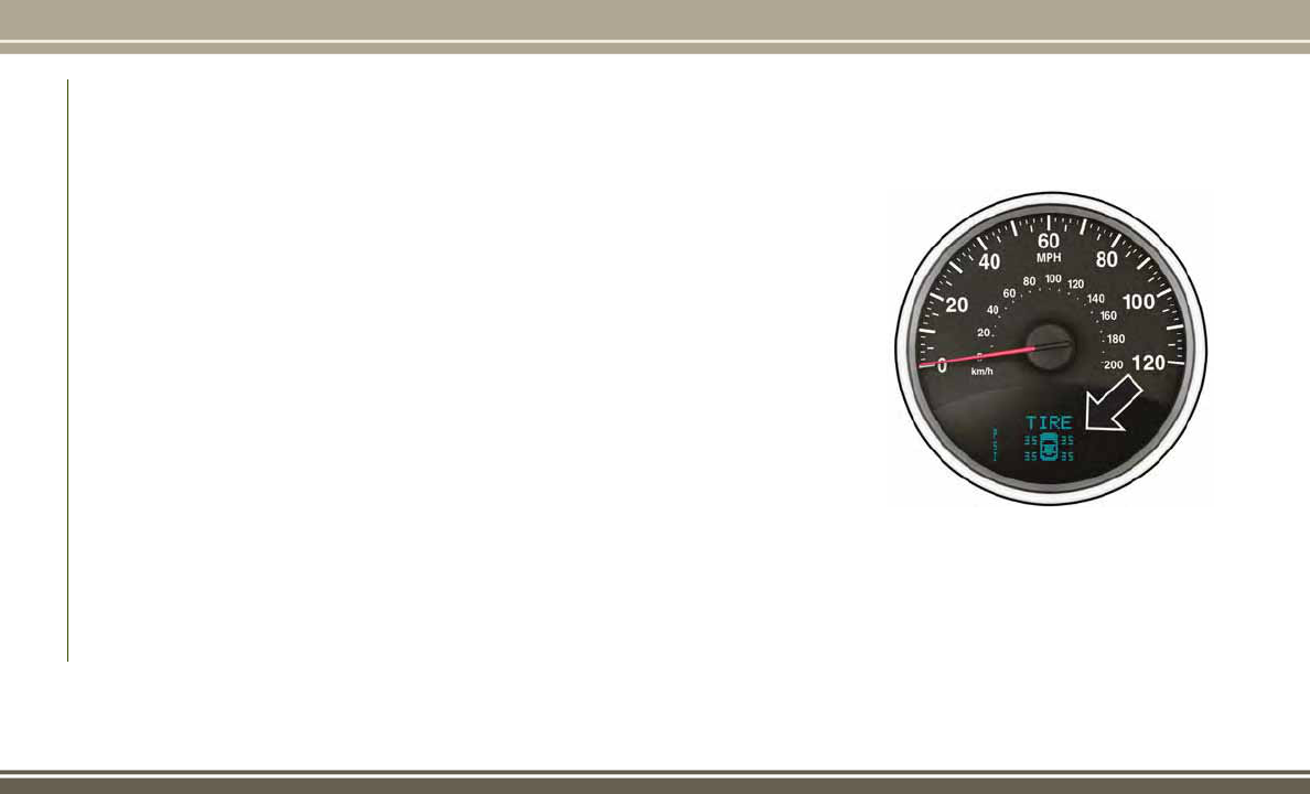
RESET Button
To reset the display shown, turn the ignition
to the ON position, then push and hold the
RESET button located on the steering wheel.
The following displays can be reset or
changed:
• Trip A
• Trip B
Trip Odometer (ODO)
This display shows the distance traveled
since the last reset. Push and release the
STEP button on the instrument cluster to
switch from odometer, to Trip A or Trip B.
Trip A
Shows the total distance traveled for Trip A
since the last reset.
Trip B
Shows the total distance traveled for Trip B
since the last reset.
INSTRUMENT CLUSTER
DISPLAY — IF EQUIPPED
Your vehicle may be equipped with an instru-
ment cluster display, which offers useful in-
formation to the driver. With the ignition in
the STOP/OFF mode, opening/closing of a
door will activate the display for viewing, and
display the total miles, or kilometers, in the
odometer. Your instrument cluster display is
designed to display important information
about your vehicle’s systems and features.
Using a driver interactive display located on
the instrument panel, your instrument clus-
ter display can show you how systems are
working and give you warnings when they
aren’t. The steering wheel mounted controls
allow you to scroll through and enter the main
menus and submenus. You can access the
specific information you want and make se-
lections and adjustments.
Interactive Display And Controls
The instrument cluster display features a
driver-interactive display that is located in
the instrument cluster.
The menu items consists of the following:
• System Status
• Units
• Vehicle Information Warning Message Dis-
plays
Instrument Cluster Display
GETTING TO KNOW YOUR INSTRUMENT PANEL
62

• Personal Settings
(Customer-Programmable Features)
• Compass Heading
• Outside Temperature Display
• Trip Computer Functions
• Uconnect Phone Displays (if equipped)
• Audio Mode Display
• Tire Pressure Monitor (TPM)
The system allows the driver to select infor-
mation by pushing the following buttons
mounted on the steering wheel:
MENU Button
Push and release the MENU button to scroll
through the main menus (Fuel Economy,
Warnings, Timer, Units, System, Personal
Settings) or to exit submenus.
Compass Button
Push and release the compass button to dis-
play one of eight compass readings and the
outside temperature or to exit submenus.
Right Arrow Button
Push and release the right arrow button for
access to main menus, submenus, or to se-
lect a personal setting in the setup menu.
Down Arrow Button
Push and release the down arrow button to
scroll downward through the submenus.
When the appropriate conditions exist, the
following messages display:
• Turn Signal On (with a continuous warning
chime after 1 mile (1.6 km) of distance
travelled)
• Left Front Turn Signal Lamp Out (with a
single chime)
• Left Rear Turn Signal Lamp Out (with a
single chime)
Instrument Cluster Display Controls
1 — Uconnect
Voice Command
Button
4 — Uconnect
Phone Button
2—
MENU Button 5 — Right Arrow
Button
3 — Compass Button 6 — Down Arrow
Button
63

• Right Front Turn Signal Lamp Out (with a
single chime)
• Right Rear Turn Signal Lamp Out (with a
single chime)
• Battery Low (with a single chime)
• Personal Settings Not Avail. — Vehicle is
not in PARK (automatic transmission), or
vehicle is in motion (manual transmission)
• Door Open (with vehicle graphic showing
which door is open. A single chime sounds
if the vehicle is in motion)
• Doors Open (with vehicle graphic showing
which doors are open. A single chime
sounds if the vehicle is in motion)
• Gate (with vehicle graphic showing the
liftgate open and a single chime)
• Headlamps or Park Lamps On
• Remote Start Aborted — Door Open
• Remote Start Aborted — Hood Open
• Remote Start Aborted — L/Gate Open
• Remote Start Aborted — Fuel Low
• Remote Start Aborted — System Fault
• Key In Ignition
• Low Tire
• Low Tire Pressure Display for Premium
TPM System
• Service TPM System
Oil Change Indicator System
Your vehicle is equipped with an engine oil
change indicator system. The “Oil Change
Required” message will display in the instru-
ment cluster display for approximately five
seconds after a single chime has sounded to
indicate the next scheduled oil change inter-
val. The engine oil change indicator system is
duty-cycle based, which means the engine oil
change interval may fluctuate dependent
upon your personal driving style.
Unless reset, this message will continue to
display each time you place the ignition in
the ON/RUN position. To turn off the mes-
sage temporarily, push and release the Trip
Odometer button on the instrument cluster.
To reset the oil change indicator system (after
performing the scheduled maintenance), re-
fer to the following procedure.
1. Place the ignition in the ON position. Do
not start the engine.
2. Fully push the accelerator pedal, slowly,
three times within ten seconds.
3. Place the ignition in the OFF/LOCK
position.
NOTE:
If the indicator message illuminates when
you start the vehicle, the oil change indicator
system did not reset. If necessary, repeat this
procedure.
Instrument Cluster Display Functions
• Compass/Temperature/Audio
• Average Fuel Economy
• Distance To Empty (DTE)
• Units In
• Elapsed Time
• Tire Pressure Monitor (TPM)
• Personal Settings
To Reset The Display
Pushing and holding the right arrow button
once will clear the function currently being
displayed. Reset will only occur if a reset-
table function is currently being displayed.
To reset all resettable functions, push and
release the right arrow button a second time
GETTING TO KNOW YOUR INSTRUMENT PANEL
64

within three seconds of resetting the cur-
rently displayed function. Reset ALL will be
displayed during this three-second window.
Compass/Temperature/Audio
Push and release the compass button to dis-
play one of eight compass headings to indi-
cate the direction the vehicle is facing, the
outside temperature, and the current radio
station.
Average Fuel Economy
Shows the average fuel economy since the
last reset (pushing and holding the right arrow
button as prompted in the instrument cluster
display to reset). When the fuel economy is
reset, the display will read “RESET” or show
dashes for two seconds. Then, the history
information will be erased, and the averaging
will continue from the last fuel reading before
the reset.
Distance To Empty (DTE)
Shows the estimated distance that can be
traveled with the fuel remaining in the tank.
This estimated distance is determined by a
weighted average of the instantaneous and
average fuel economy, according to the cur-
rent fuel tank level. This is not resettable.
NOTE:
Significant changes in driving style or vehicle
loading will greatly affect the actual drivable
distance of the vehicle, regardless of the DTE
displayed value.
When the DTE value is less than 30 miles
(48 km) estimated driving distance, the DTE
display will change to a text display of "LOW
FUEL." This display will continue until the
vehicle runs out of fuel. Adding a significant
amount of fuel to the vehicle will turn off the
"LOW FUEL" text and a new DTE value will be
displayed, based on the current values in the
DTE calculation and the current fuel tank
level.
Tire Pressure Monitor (TPM)
Refer to “Tire Pressure Monitoring System
(TPMS)” in “Safety” for system operation.
Elapsed Time
Shows the total elapsed time of travel since
the last reset. Elapsed time will increment
when the ignition is placed in the RUN/
START position.
Elapsed time is displayed as follows:
hours: minutes: seconds
Elapsed time can be reset by pushing and
holding the right arrow button (as prompted
in the display). Upon reset, all digits will
change to zeros, and time will start again if
the ignition is in the RUN or START position.
Display Units Of Measure In
To make your selection, push and release the
right arrow button until “US” or “METRIC”
appears.
Personal Settings (Customer-
Programmable Features)
This allows the driver to set and recall fea-
tures when the transmission is in PARK (au-
tomatic transmission) or the vehicle is
stopped (manual transmission).
65

Push and release the MENU or down arrow
button until “Personal Settings” is displayed
in the instrument cluster display then push
and release the right arrow button.
Use the right arrow button to highlight your
MENU/SUBMENU choices:
ONBOARD DIAGNOSTIC
SYSTEM — OBD II
Your vehicle is equipped with a sophisticated
Onboard Diagnostic system called OBD II.
This system monitors the performance of the
emissions, engine, and automatic transmis-
sion control systems. When these systems are
operating properly, your vehicle will provide
excellent performance and fuel economy, as
well as emissions well within current govern-
ment regulations.
If any of these systems require service, the
OBD II system will turn on the Malfunction
Indicator Light (MIL). It will also store diag-
nostic codes and other information to assist
your service technician in making repairs.
Although your vehicle will usually be drivable
and not need towing, see your authorized
dealer for service as soon as possible.
CAUTION!
• Prolonged driving with the MIL on could
cause further damage to the emission
control system. It could also affect fuel
economy and driveability. The vehicle
must be serviced before any emissions
tests can be performed.
• If the MIL is flashing while the vehicle is
running, severe catalytic converter dam-
age and power loss will soon occur. Im-
mediate service is required.
Onboard Diagnostic System (OBD II)
Cybersecurity
Your vehicle is required to have an Onboard
Diagnostic system (OBD II) and a connection
port to allow access to information related to
the performance of your emissions controls.
Authorized service technicians may need to
access this information to assist with the
diagnosis and service of your vehicle and
emissions system.
WARNING!
• ONLY an authorized service technician
should connect equipment to the OBD II
connection port in order to diagnose or
service your vehicle.
• If unauthorized equipment is connected
to the OBD II connection port, such as a
driver-behavior tracking device, it may:
• Be possible that vehicle systems,
including safety related systems,
could be impaired or a loss of ve-
hicle control could occur that may
result in an accident involving seri-
ous injury or death.
• Access, or allow others to access,
information stored in your vehicle
systems, including personal infor-
mation.
For further information, refer to “Cybersecu-
rity” in “Multimedia” in your Owner's Manual
at www.jeep.com/en/owners/manuals/.
GETTING TO KNOW YOUR INSTRUMENT PANEL
66

Loose Fuel Filler Cap Message
After fuel is added, the vehicle diagnostic
system can determine if the fuel filler cap is
possibly loose or improperly installed. A
“gASCAP” message will be displayed in the
instrument cluster. Tighten the gas cap until
a “clicking” sound is heard. This is an indi-
cation that the gas cap is properly tightened.
Push the trip odometer RESET button to turn
off the message. If the problem persists, the
message will appear the next time the vehicle
is started. This might indicate a damaged
cap. If the problem is detected twice in a row,
the system will turn on the MIL. Resolving the
problem will turn the MIL light off.
EMISSIONS INSPECTION
AND MAINTENANCE
PROGRAMS
In some localities, it may be a legal require-
ment to pass an inspection of your vehicle's
emissions control system. Failure to pass
could prevent vehicle registration.
For states that require an
Inspection and Mainte-
nance (I/M), this check
verifies the “Malfunction
Indicator Light (MIL)” is
functioning and is not on
when the engine is run-
ning, and that the OBD II system is ready for
testing.
Normally, the OBD II system will be ready.
The OBD II system may not be ready if your
vehicle was recently serviced, recently had a
dead battery or a battery replacement. If the
OBD II system should be determined not
ready for the I/M test, your vehicle may fail
the test.
Your vehicle has a simple ignition actuated
test, which you can use prior to going to the
test station. To check if your vehicle's OBD II
system is ready, you must do the following:
1. Cycle the ignition switch to the ON posi-
tion, but do not crank or start the engine.
NOTE:
If you crank or start the engine, you will
have to start this test over.
2. As soon as you cycle the ignition switch to
the ON position, you will see the “Mal-
function Indicator Light (MIL)” symbol
come on as part of a normal bulb check.
3. Approximately 15 seconds later, one of
two things will happen:
• The MIL will flash for about 10 seconds
and then return to being fully illuminated
until you turn OFF the ignition or start the
engine. This means that your vehicle's
OBD II system is not ready and you should
not proceed to the I/M station.
67

• The MIL will not flash at all and will
remain fully illuminated until you place
the ignition in the off position or start the
engine. This means that your vehicle's
OBD II system is ready and you can pro-
ceed to the I/M station.
If your OBD II system is not ready, you should
see your authorized dealer or repair facility. If
your vehicle was recently serviced or had a
battery failure or replacement, you may need
to do nothing more than drive your vehicle as
you normally would in order for your OBD II
system to update. A recheck with the above
test routine may then indicate that the sys-
tem is now ready.
Regardless of whether your vehicle's OBD II
system is ready or not, if the MIL is illumi-
nated during normal vehicle operation you
should have your vehicle serviced before go-
ing to the I/M station. The I/M station can fail
your vehicle because the MIL is on with the
engine running.
GETTING TO KNOW YOUR INSTRUMENT PANEL
68

SAFETY
SAFETY FEATURES...........70
Anti-Lock Brake System (ABS) ......70
Electronic Brake Control System .....71
AUXILIARY DRIVING SYSTEMS . .77
Tire Pressure Monitoring System
(TPMS) .....................77
OCCUPANT RESTRAINT
SYSTEMS ..................83
Occupant Restraint Systems Features . .83
Important Safety Precautions .......84
Seat Belt Systems ..............84
Supplemental Restraint Systems (SRS). .95
Child Restraints ...............104
Transporting Pets ..............115
SAFETY TIPS ...............115
Transporting Passengers ..........115
Exhaust Gas .................115
Safety Checks You Should Make Inside The
Vehicle ....................116
Periodic Safety Checks You Should Make
Outside The Vehicle.............117
SAFETY
69

SAFETY FEATURES
Anti-Lock Brake System (ABS)
The Anti-Lock Brake System (ABS) provides
increased vehicle stability and brake perfor-
mance under most braking conditions. The
system automatically prevents wheel lock,
and enhances vehicle control during braking.
The ABS performs a self-check cycle to en-
sure that the ABS is working properly each
time the vehicle is started and driven. During
this self-check, you may hear a slight clicking
sound as well as some related motor noises.
ABS is activated during braking when the
system detects one or more wheels begin to
lock. Road conditions such as ice, snow,
gravel, bumps, railroad tracks, loose debris,
or panic stops may increase the likelihood of
ABS activation(s).
You also may experience the following when
ABS activates:
• The ABS motor noise (it may continue to
run for a short time after the stop).
• The clicking sound of solenoid valves.
• Brake pedal pulsations.
• A slight drop of the brake pedal at the end
of the stop.
These are all normal characteristics of ABS.
WARNING!
• The ABS contains sophisticated elec-
tronic equipment that may be suscep-
tible to interference caused by improp-
erly installed or high output radio
transmitting equipment. This interfer-
ence can cause possible loss of anti-lock
braking capability. Installation of such
equipment should be performed by
qualified professionals.
• Pumping of the Anti-Lock Brakes will
diminish their effectiveness and may
lead to a collision. Pumping makes the
stopping distance longer. Just press
firmly on your brake pedal when you
need to slow down or stop.
• The ABS cannot prevent the natural laws
of physics from acting on the vehicle,
nor can it increase braking or steering
efficiency beyond that afforded by the
WARNING!
condition of the vehicle brakes and tires
or the traction afforded.
• The ABS cannot prevent collisions, in-
cluding those resulting from excessive
speed in turns, following another vehicle
too closely, or hydroplaning.
• The capabilities of an ABS equipped
vehicle must never be exploited in a
reckless or dangerous manner that could
jeopardize the user’s safety or the safety
of others.
ABS is designed to function with the OEM
tires. Modification may result in degraded
ABS performance.
Anti-Lock Brake Warning Light
The yellow “Anti-Lock Brake Warning Light”
will turn on when the ignition is turned to the
ON/RUN mode and may stay on for as long as
four seconds.
If the “Anti-Lock Brake Warning Light” re-
mains on or comes on while driving, it indi-
cates that the anti-lock portion of the brake
system is not functioning and that service is
SAFETY
70

required. However, the conventional brake
system will continue to operate normally if
the “Brake System Warning Light” is not on.
If the “Anti-Lock Brake Warning Light” is on,
the brake system should be serviced as soon
as possible to restore the benefits of anti-lock
brakes. If the “Anti-Lock Brake Warning
Light” does not come on when the ignition is
turned to the ON/RUN mode, have the light
repaired as soon as possible.
Electronic Brake Control System
Your vehicle is equipped with an advanced
Electronic Brake Control system (EBC). This
system includes Electronic Brake Force Dis-
tribution (EBD), Anti-Lock Brake System
(ABS), Brake Assist System (BAS), Hill Start
Assist (HSA), Traction Control System (TCS),
Electronic Stability Control (ESC), and Elec-
tronic Roll Mitigation (ERM). These systems
work together to enhance both vehicle stabil-
ity and control in various driving conditions.
Your vehicle may also be equipped with Hill
Descent Control (HDC).
Electronic Brake Force Distribution (EBD)
This function manages the distribution of the
braking torque between the front and rear
axles by limiting braking pressure to the rear
axle. This is done to prevent overslip of the
rear wheels to avoid vehicle instability, and to
prevent the rear axle from entering ABS be-
fore the front axle.
Brake System Warning Light
The red “Brake System Warning Light” will
turn on when the ignition is turned to the
ON/RUN mode and may stay on for as long as
four seconds.
If the “Brake System Warning Light” remains
on or comes on while driving, it indicates that
the brake system is not functioning properly
and that immediate service is required. If the
“Brake System Warning Light” does not
come on when the ignition is turned to the
ON/RUN mode, have the light repaired as
soon as possible.
Brake Assist System (BAS)
The BAS is designed to optimize the vehicle’s
braking capability during emergency braking
maneuvers. The system detects an emer-
gency braking situation by sensing the rate
and amount of brake application and then
applies optimum pressure to the brakes. This
can help reduce braking distances. The BAS
complements the anti-lock brake system
(ABS). Applying the brakes very quickly re-
sults in the best BAS assistance. To receive
the benefit of the system, you must apply
continuous braking pressure during the stop-
ping sequence, (do not “pump” the brakes).
Do not reduce brake pedal pressure unless
braking is no longer desired. Once the brake
pedal is released, the BAS is deactivated.
WARNING!
The Brake Assist System (BAS) cannot
prevent the natural laws of physics from
acting on the vehicle, nor can it increase
the traction afforded by prevailing road
conditions. BAS cannot prevent collisions,
including those resulting from excessive
71

WARNING!
speed in turns, driving on very slippery
surfaces, or hydroplaning. The capabilities
of a BAS-equipped vehicle must never be
exploited in a reckless or dangerous man-
ner, which could jeopardize the user's
safety or the safety of others.
Hill Start Assist (HSA)
The HSA system is designed to mitigate roll
back from a complete stop while on an in-
cline. If the driver releases the brake while
stopped on an incline, HSA will continue to
hold the brake pressure for a short period. If
the driver does not apply the throttle before
this time expires, the system will release
brake pressure and the vehicle will roll down
the hill as normal.
The following conditions must be met in
order for HSA to activate:
• The feature must be enabled.
• The vehicle must be stopped.
• Park brake must be off.
• Driver door must be closed.
• The vehicle must be on a sufficient grade.
• The gear selection must match vehicle
uphill direction (i.e., vehicle facing uphill
is in forward gear; vehicle backing uphill is
in REVERSE gear).
• HSA will work in REVERSE gear and all
forward gears. The system will not activate
if the transmission is in PARK or NEU-
TRAL. For vehicles equipped with a
manual transmission, if the clutch is
pressed, HSA will remain active.
WARNING!
There may be situations where the Hill
Start Assist (HSA) will not activate and
slight rolling may occur, such as on minor
hills or with a loaded vehicle, or while
pulling a trailer. HSA is not a substitute for
active driving involvement. It is always the
driver’s responsibility to be attentive to
distance to other vehicles, people, and
objects, and most importantly brake op-
eration to ensure safe operation of the
vehicle under all road conditions. Your
complete attention is always required
while driving to maintain safe control of
WARNING!
your vehicle. Failure to follow these warn-
ings can result in a collision or serious
personal injury.
Disabling And Enabling HSA
This feature can be turned on or turned off.
To change the current setting using your
instrument cluster display, refer to “Instru-
ment Cluster Display” in “Getting To Know
Your Instrument Panel” for further informa-
tion.
For vehicles not equipped with an instrument
cluster display, perform the following steps:
1. Center the steering wheel (front wheels
pointing straight forward).
2. Shift the transmission into PARK.
3. Apply the parking brake.
4. Start the engine.
5. Rotate the steering wheel slightly more
than one-half turn to the left.
SAFETY
72

6. Push the “ESC Off” button located in the
lower switch bank below the climate con-
trol four times within 20 seconds. The
“ESC Off Indicator Light” should turn on
and turn off two times.
7. Rotate the steering wheel back to center
and then an additional slightly more than
one-half turn to the right.
8. Turn the ignition to the OFF mode and
then back to ON. If the sequence was
completed properly, the “ESC Off Indica-
tor Light” will blink several times to con-
firm HSA is disabled.
9. Repeat these steps if you want to return
this feature to its previous setting.
Traction Control System (TCS)
This system monitors the amount of wheel
spin of each of the driven wheels. If wheel
spin is detected, the TCS may apply brake
pressure to the spinning wheel(s) and/or re-
duce engine power to provide enhanced ac-
celeration and stability. A feature of the TCS,
Brake Limited Differential (BLD), functions
similar to a limited slip differential and con-
trols the wheel spin across a driven axle. If
one wheel on a driven axle is spinning faster
than the other, the system will apply the
brake of the spinning wheel. This will allow
more engine torque to be applied to the wheel
that is not spinning. BLD may remain en-
abled even if TCS and ESC are in a reduced
mode.
Electronic Stability Control (ESC)
This system enhances directional control and
stability of the vehicle under various driving
conditions. ESC corrects for oversteering or
understeering of the vehicle by applying the
brake of the appropriate wheel(s) to assist in
counteracting the oversteer or understeer
condition. Engine power may also be reduced
to help the vehicle maintain the desired path.
ESC uses sensors in the vehicle to determine
the vehicle path intended by the driver and
compares it to the actual path of the vehicle.
When the actual path does not match the
intended path, ESC applies the brake of the
appropriate wheel to assist in counteracting
the oversteer or understeer condition.
• Oversteer — when the vehicle is turning
more than appropriate for the steering
wheel position.
• Understeer — when the vehicle is turning
less than appropriate for the steering
wheel position.
The “ESC Activation/Malfunction Indicator
Light” located in the instrument cluster will
start to flash as soon as the ESC system
becomes active. The “ESC Activation/
Malfunction Indicator Light” also flashes
when the TCS is active. If the “ESC
Activation/Malfunction Indicator Light” be-
gins to flash during acceleration, ease up on
the accelerator and apply as little throttle as
possible. Be sure to adapt your speed and
driving to the prevailing road conditions.
WARNING!
•
Electronic Stability Control (ESC) cannot
prevent the natural laws of physics from
acting on the vehicle, nor can it increase
the traction afforded by prevailing road
conditions. ESC cannot prevent acci-
dents, including those resulting from ex-
cessive speed in turns, driving on very
slippery surfaces, or hydroplaning. ESC
also cannot prevent accidents resulting
73

WARNING!
from loss of vehicle control due to inap-
propriate driver input for the conditions.
Only a safe, attentive, and skillful driver
can prevent accidents. The capabilities of
an ESC equipped vehicle must never be
exploited in a reckless or dangerous man-
ner which could jeopardize the user’s
safety or the safety of others.
• Vehicle modifications, or failure to prop-
erly maintain your vehicle, may change
the handling characteristics of your ve-
hicle, and may negatively affect the per-
formance of the ESC system. Changes to
the steering system, suspension, brak-
ing system, tire type and size or wheel
size may adversely affect ESC perfor-
mance. Improperly inflated and un-
evenly worn tires may also degrade ESC
performance. Any vehicle modification
or poor vehicle maintenance that re-
duces the effectiveness of the ESC sys-
tem can increase the risk of loss of
vehicle control, vehicle rollover, per-
sonal injury and death.
ESC Operating Modes
The ESC system has three available operating
modes for four–wheel drive equipped ve-
hicles and two available operating modes for
two–wheel drive equipped vehicles.
Full On (Four-Wheel Drive Models) Or On (Two-
Wheel Drive Models)
This is the normal operating mode for ESC.
Whenever the vehicle is started, the ESC
system will be in this “On” mode. This mode
should be used for most driving situations.
ESC should only be turned to “Partial Off” or
“ESC Off” for specific reasons as noted be-
low.
Partial Off (Four-Wheel Drive Models) Or On
(Two-Wheel Drive Models)
This mode is entered by momentarily pushing
the “ESC Off” switch. When in “Partial Off”
mode, the TCS portion of ESC, except for the
“limited slip” feature described in the TCS
section, has been disabled, and the "ESC
OFF Indicator Light" will be illuminated. All
other stability features of ESC function nor-
mally. This mode is intended to be used if the
vehicle is in deep snow, sand or gravel con-
ditions, and more wheel spin than ESC would
normally allow is required to gain traction.
To turn ESC on again, momentarily push the
“ESC Off” switch. This will restore the nor-
mal “ESC On” mode of operation.
NOTE:
To improve the vehicle's traction when driving
with snow chains, or starting off in deep
snow, sand or gravel, it may be desirable to
switch to the “Partial Off” mode by pushing
the “ESC Off” switch. Once the situation
requiring ESC to be switched to the “Partial
Off” mode is overcome, turn ESC back on by
momentarily pushing the “ESC Off” switch.
This may be done while the vehicle is in
motion.
WARNING!
When in “Partial Off” mode, the TCS func-
tionality of ESC (except for the limited slip
feature described in the TCS section) has
been disabled and the “ESC Off Indicator
Light” will be illuminated. When in “Par-
tial Off” mode, the engine power reduction
SAFETY
74

WARNING!
of TCS is disabled, and the enhanced
vehicle stability offered by the ESC system
is reduced. Trailer Sway control (TSC) (if
equipped) is disabled when the ESC sys-
tem is in the "Partial Off" mode.
Full Off (Four-Wheel Drive Models Only)
This mode is intended for off-highway or
off-road use when ESC stability features
could inhibit vehicle maneuverability due to
trail conditions. This mode is entered by
pushing and holding the “ESC Off” switch for
five seconds when the vehicle is stopped and
the engine is running. After five seconds, the
"ESC OFF Indicator Light" will illuminate and
the “ESC OFF” message will appear in the
odometer. Push and release the Trip Odom-
eter button located on the instrument cluster
to clear this message.
In this mode, ESC and TCS, except for the
“limited slip” feature described in the TCS
section, are turned off until the vehicle
reaches a speed of 35 mph (56 km/h). At
35 mph (56 km/h), the system returns to
“Partial Off” mode, as described above. TCS
remains off. When the vehicle speed drops
below 30 mph (48 km/h), the ESC system
shuts off. ESC is deactivated at low vehicle
speeds so that it will not interfere with off-
road driving however, ESC function returns to
provide the stability feature at speeds above
35 mph (56 km/h). The "ESC OFF Indicator
Light" will always be illuminated when ESC is
off.
To turn ESC on again, momentarily push the
“ESC Off” switch. This will restore the “ESC
On” mode of operation.
NOTE:
The “ESC OFF” message will display and an
audible chime will sound when the gear se-
lector is placed into the PARK position from
any other position, and then moved out of the
PARK position. This will occur even if the
message was previously cleared.
WARNING!
In the "Full Off" mode, the engine torque
reduction and stability features are dis-
abled. In an emergency evasive maneuver,
the ESC system will not engage to assist in
WARNING!
maintaining stability. “ESC Off” mode is
intended for off-highway or off-road use
only.
ESC Activation/Malfunction Indicator Light
and ESC OFF Indicator Light
The “ESC Activation/
Malfunction Indicator
Light” in the instrument
cluster will come on when
the ignition is turned to
the ON mode. It should go
out with the engine run-
ning. If the “ESC Activation/Malfunction In-
dicator Light” comes on continuously with
the engine running, a malfunction has been
detected in the ESC system. If this light
remains on after several ignition cycles, and
the vehicle has been driven several miles
(kilometers) at speeds greater than 30 mph
(48 km/h), see your authorized dealer as soon
as possible to have the problem diagnosed
and corrected.
75
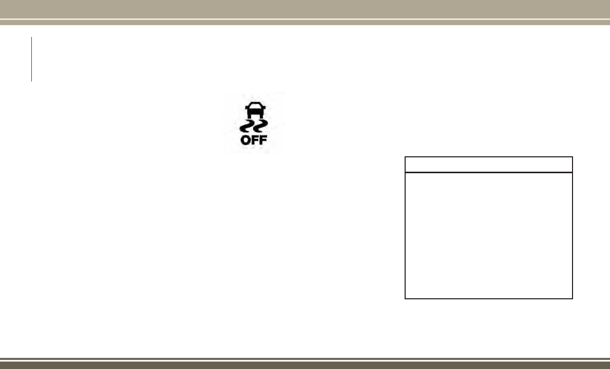
The “ESC Activation/Malfunction Indicator
Light” (located in the instrument cluster)
starts to flash as soon as the tires lose trac-
tion and the ESC system becomes active. The
“ESC Activation/Malfunction Indicator
Light” also flashes when TCS is active. If the
“ESC Activation/Malfunction Indicator
Light” begins to flash during acceleration,
ease up on the accelerator and apply as little
throttle as possible. Be sure to adapt your
speed and driving to the prevailing road con-
ditions.
NOTE:
• The “ESC Activation/Malfunction Indica-
tor Light” and the “ESC OFF Indicator
Light” come on momentarily each time
the ignition is turned ON.
• Each time the ignition is turned ON, the
ESC system will be on even if it was turned
off previously.
• The ESC system will make buzzing or
clicking sounds when it is active. This is
normal; the sounds will stop when ESC
becomes inactive following the maneuver
that caused the ESC activation.
The “ESC OFF Indicator
Light” indicates the cus-
tomer has elected to have
the Electronic Stability
Control (ESC) in a re-
duced mode.
Electronic Roll Mitigation (ERM)
This system anticipates the potential for
wheel lift by monitoring the driver’s steering
wheel input and the speed of the vehicle.
When ERM determines that the rate of
change of the steering wheel angle and vehi-
cle’s speed are sufficient to potentially cause
wheel lift, it then applies the appropriate
brake and may also reduce engine power to
lessen the chance that wheel lift will occur.
ERM can only reduce the chance of wheel lift
occurring during severe or evasive driving
maneuvers; it cannot prevent wheel lift due
to other factors, such as road conditions,
leaving the roadway, or striking objects or
other vehicles.
NOTE:
ERM is disabled anytime the ESC is in “Full
Off” mode (if equipped). Refer to “Electronic
Stability Control (ESC)” in this section for a
complete explanation of the available ESC
modes.
WARNING!
Many factors, such as vehicle loading,
road conditions and driving conditions,
influence the chance that wheel lift or
rollover may occur. ERM cannot prevent
all wheel lift or roll overs, especially those
that involve leaving the roadway or striking
objects or other vehicles. The capabilities
of an ERM-equipped vehicle must never
be exploited in a reckless or dangerous
manner which could jeopardize the user's
safety or the safety of others.
SAFETY
76

Hill Descent Control (HDC) — If Equipped
This system maintains vehicle speed while
descending hills during off-road driving situ-
ations. HDC will automatically apply the
brakes to control downhill speed to between
4 mph (7 km/h) and 6 mph (9 km/h) depend-
ing on terrain. The system is activated by
placing the vehicle in “Off-Road” mode and
placing the gear selector in LOW or RE-
VERSE. Refer to “Off-Road Driving Tips” in
“Starting And Operating” for further informa-
tion.
When HDC is properly en-
abled, the “Hill Decent
Control Light” in the in-
strument cluster will be
illuminated.
HDC has the capability to
sense terrain and will only activate when the
vehicle is descending a hill. It will not acti-
vate on level ground. If desired, HDC can be
fully deactivated by putting the vehicle into
ESC “Full Off” mode. This is done by pushing
and holding the “ESC Off” button for five
seconds. Refer to “Electronic Stability Con-
trol (ESC)” in this section of the manual.
HDC operation can be overridden with brake
application to slow the vehicle down below
the HDC control speed. Conversely, if more
speed is desired during HDC control, the
accelerator pedal will increase vehicle speed
like normal. When either the brake or the
accelerator is released, HDC will control the
vehicle back to the original set speed.
HDC is only intended for low speed off-road
driving. At vehicle speeds above 31 mph
(50 km/h), HDC will no longer function. If the
“HDC Indicator Light” begins to flash, this
indicates that the brakes are getting too hot
and the vehicle should be stopped to allow
the brakes to cool.
WARNING!
HDC is only intended to assist the driver in
controlling vehicle speed when descend-
ing hills. The driver must remain attentive
to the driving conditions and is responsible
for maintaining a safe vehicle speed.
AUXILIARY DRIVING
SYSTEMS
Tire Pressure Monitoring System (TPMS)
The Tire Pressure Monitor System (TPMS)
will warn the driver of a low tire pressure
based on the vehicle recommended cold
placard pressure.
The tire pressure will vary with temperature
by about 1 psi (7.0 kPa) for every 12°F
(6.5°C). This means that when the outside
temperature decreases, the tire pressure will
decrease. Tire pressure should always be set
based on “cold inflation tire pressure”. This
is defined as the tire pressure after the ve-
hicle has not been driven for at least three
hours, or driven less than 1 mile (1.6 km)
after a three hour period. The cold tire infla-
tion pressure must not exceed the maximum
inflation pressure molded into the tire side-
wall. Refer to “Tires – General Information”
in “Servicing And Maintenance” for informa-
tion on how to properly inflate the vehicle’s
77

tires. The tire pressure will also increase as
the vehicle is driven - this is normal and there
should be no adjustment for this increased
pressure.
The TPMS will warn the driver of a low tire
pressure if the tire pressure falls below the
low-pressure warning limit for any reason,
including low temperature effects, or natural
pressure loss through the tire.
The TPMS will continue to warn the driver of
low tire pressure as long as the condition
exists, and will not turn off until the tire
pressure is at or above the recommended
cold placard pressure. Once the low tire pres-
sure warning (Tire Pressure Monitoring Tell-
tale Light) illuminates, you must increase the
tire pressure to the recommended cold plac-
ard pressure in order for the Tire Pressure
Monitoring Telltale Light to turn off. The
system will automatically update and the Tire
Pressure Monitoring Telltale Light will turn
off once the system receives the updated tire
pressures.
NOTE:
When filling warm tires, the tire pressure may
need to be increased up to an additional 4 psi
(30 kPa) above the recommended cold plac-
ard pressure in order to turn the Tire Pressure
Monitoring Telltale Light off. The vehicle may
need to be driven for up to 10 minutes above
15 mph (24 km/h) in order for the TPMS to
receive this information.
For example, your vehicle may have a recom-
mended cold (parked for more than three
hours) placard pressure of 30 psi (207 kPa).
If the ambient temperature is 68°F (20°C)
and the measured tire pressure is 27 psi
(186 kPa), a temperature drop to 20°F (-7°C)
will decrease the tire pressure to approxi-
mately 23 psi (158 kPa). This tire pressure is
sufficiently low enough to turn ON the Tire
Pressure Monitoring Telltale Light. Driving
the vehicle may cause the tire pressure to rise
to approximately 27 psi (186 kPa), but the
Tire Pressure Monitoring Telltale Light will
still be ON. In this situation, the Tire Pressure
Monitoring Telltale Light will turn OFF only
after the tires are inflated to the vehicle’s
recommended cold placard pressure value.
NOTE:
When filling warm tires, the tire pressure may
need to be increased up to an additional 4 psi
(30 kPa) above the recommended cold plac-
ard pressure in order to turn the Tire Pressure
Monitoring Telltale Light off.
CAUTION!
• The TPMS has been optimized for the
original equipment tires and wheels.
TPMS pressures and warning have been
established for the tire size equipped on
your vehicle. Undesirable system opera-
tion or sensor damage may result when
using replacement equipment that is not
of the same size, type, and/or style.
Aftermarket wheels can cause sensor
damage.
• Using aftermarket tire sealants may
cause the Tire Pressure Monitoring Sys-
tem (TPMS) sensor to become inoper-
able. After using an aftermarket tire
sealant it is recommended that you take
your vehicle to an authorized dealer to
have your sensor function checked.
SAFETY
78

CAUTION!
• After inspecting or adjusting the tire
pressure always reinstall the valve stem
cap. This will prevent moisture and dirt
from entering the valve stem, which
could damage the TPMS sensor.
NOTE:
• The TPMS is not intended to replace nor-
mal tire care and maintenance or to pro-
vide warning of a tire failure or condition.
• The TPMS should not be used as a tire
pressure gauge while adjusting your tire
pressure.
• Driving on a significantly under-inflated
tire causes the tire to overheat and can
lead to tire failure. Under-inflation also
reduces fuel efficiency and tire tread life,
and may affect the vehicle’s handling and
stopping ability.
• The TPMS is not a substitute for proper
tire maintenance, and it is the driver’s
responsibility to maintain correct tire pres-
sure using an accurate tire gauge, even if
under-inflation has not reached the level
to trigger illumination of the Tire Pressure
Monitoring Telltale Light.
• Seasonal temperature changes will affect
tire pressure, and the TPMS will monitor
the actual tire pressure in the tire.
Base System
This is the TPMS warning
indicator located in the in-
strument cluster.
The TPMS uses wireless
technology with wheel rim
mounted electronic sen-
sors to monitor tire pressure levels. Sensors,
mounted to each wheel as part of the valve
stem, transmit tire pressure readings to the
Receiver Module.
NOTE:
It is particularly important for you to check
the tire pressure in all of the tires on your
vehicle regularly and to maintain the proper
pressure.
The TPMS consists of the following compo-
nents:
• Receiver Module.
• Four Tire Pressure Monitoring Sensors.
• Tire Pressure Monitoring Telltale Light.
Tire Pressure Monitoring Low Pressure Warn-
ings
The Tire Pressure Monitoring Telltale Light
will illuminate in the instrument cluster, a
LOW TIRE message will be displayed for a
minimum of five seconds, and an audible
chime will be activated when one or more of
the four active road tire pressures are low.
Should this occur, you should stop as soon as
possible, check the inflation pressure of each
tire on your vehicle, and inflate each tire to
the vehicle’s recommended cold placard
pressure value. The system will automatically
update and the Tire Pressure Monitoring
Light will extinguish and the LOW TIRE mes-
sage will turn off once the updated tire pres-
sures have been received.
79

NOTE:
When filling warm tires, the tire pressure may
need to be increased up to an additional 4 psi
(30 kPa) above the recommended cold plac-
ard pressure in order to turn the Tire Pressure
Monitoring Telltale Light off.The vehicle may
need to be driven for up to 10 minutes above
15 mph (24 km/h) to receive this informa-
tion.
Check TPMS Warnings
The Tire Pressure Monitoring Telltale Light
will flash on and off for 75 seconds and
remain on solid when a system fault is de-
tected. The system fault will also sound a
chime. If the ignition key is cycled, this
sequence will repeat providing the system
fault still exists. The Tire Pressure Monitoring
Telltale Light will turn off when the fault
condition no longer exists. A system fault can
occur with any of the following scenarios:
1. Jamming due to electronic devices or driv-
ing next to facilities emitting the same
radio frequencies as the TPM sensors.
2. Installing some form of aftermarket win-
dow tinting that affects radio wave
signals.
3. Snow or ice around the wheels or wheel
housings.
4. Using tire chains on the vehicle.
5. Using wheels/tires not equipped with
TPM sensors.
NOTE:
Your vehicle is equipped with a compact
spare wheel and tire assembly.
1. The compact spare tire does not have a
tire pressure monitoring sensor. There-
fore, the TPMS will not monitor the tire
pressure in the compact spare tire.
2. If you install the compact spare tire in
place of a road tire that has a pressure
below the low-pressure warning limit,
upon the next ignition key cycle, a chime
will sound and the Tire Pressure Monitor-
ing Telltale Light and LOW TIRE message
will still turn ON due to the low tire.
3. However, after driving the vehicle for up to
10 minutes above 15 mph (24 km/h), the
Tire Pressure Monitoring Telltale Light will
flash on and off for 75 seconds and then
remain on solid.
SAFETY
80

4. For each subsequent ignition key cycle, a
chime will sound and the Tire Pressure
Monitoring Telltale Light will flash on and
off for 75 seconds and then remain on
solid.
5. Once you repair or replace the original
road tire and reinstall it on the vehicle in
place of the compact spare tire, the TPMS
will update automatically and the Tire
Pressure Monitoring Telltale Light will
turn OFF, as long as no tire pressure is
below the low-pressure warning limit in
any of the four active road tires. The
vehicle may need to be driven for up to
10 minutes above 15 mph (24 km/h) in
order for the TPMS to receive this
information.
Premium System — If Equipped
The TPMS uses wireless technology with
wheel rim mounted electronic sensors to
monitor tire pressure levels. Sensors,
mounted to each wheel as part of the valve
stem, transmit tire pressure readings to the
receiver module.
NOTE:
It is particularly important for you to check
the tire pressure in all of your tires regularly
and to maintain the proper pressure.
The TPMS consists of the following compo-
nents:
• Receiver Module
• Four Tire Pressure Monitoring Sensors
• Three Trigger Modules (mounted in three
of the four wheel wells)
• Various Tire Pressure Monitoring System
Messages, which display in the instrument
cluster
• Tire Pressure Monitoring Telltale Light
Tire Pressure Monitoring Low Pressure Warn-
ings
The Tire Pressure Monitoring Telltale Light
will illuminate in the instrument cluster and
an audible chime will be activated when one
or more of the four active road tire pressures
are low. The audible chime will sound once
every ignition cycle for the first condition that
it detects. In addition, the instrument cluster
will display a “LOW TIRE” text message for a
minimum of five seconds and a graphic of the
pressure value(s) with the low tire(s) flashing.
Should a low tire condition occur on any of
the four active road tire(s), you should stop as
soon as possible and inflate all tires that are
flashing on the graphic display to the vehi-
cle’s recommended cold placard pressure
value. The system will automatically update,
the “LOW TIRE” text message will no longer
be displayed, the graphic display of the pres-
Tire Pressure Monitoring Display
81

sure value(s) will stop flashing, and the Tire
Pressure Monitoring Light will extinguish
once the updated tire pressure(s) have been
received.
NOTE:
When filling warm tires, the tire pressure may
need to be increased up to an additional 4 psi
(30 kPa) above the recommended cold plac-
ard pressure in order to turn the Tire Pressure
Monitoring Telltale Light off.The vehicle may
need to be driven for up to 10 minutes above
15 mph (24 km/h) to receive this informa-
tion.
Service TPMS Message
The Tire Pressure Monitoring Telltale Light
will flash on and off for 75 seconds, and
remain on solid when a system fault is de-
tected. The system fault will also sound a
chime. The instrument cluster will display a
“SERVICE TPM SYSTEM” message for a
minimum of five seconds. This text message
is then followed by a graphic display, with “-
-“ in place of the pressure value(s) indicating
which Tire Pressure Monitoring Sensor(s) is
not being received.
If the ignition key is cycled, this sequence
will repeat, providing the system fault still
exists. If the system fault no longer exists, the
Tire Pressure Monitoring Telltale Light will no
longer flash, the "SERVICE TPM SYSTEM"
text message will not be present, and a pres-
sure value will be displayed instead of
dashes. A system fault can occur with any of
the following scenarios:
1. Jamming due to electronic devices or driv-
ing next to facilities emitting the same
radio frequencies as the TPM sensors.
2. Installing some form of aftermarket win-
dow tinting that affects radio wave
signals.
3. Snow or ice around the wheels or wheel
housings.
4. Using tire chains on the vehicle.
5. Using wheels/tires not equipped with
TPM sensors.
The instrument cluster will also display a
"SERVICE TPM SYSTEM" message for a mini-
mum of five seconds when a system fault
related to an incorrect sensor location fault is
detected. In this case, the "SERVICE TPM
SYSTEM" message is then followed with a
graphic display with pressure values still
shown. This indicates that the pressure val-
ues are still being received from the TPM
sensors but they may not be located in the
correct vehicle position. The system still
needs to be serviced as long as the "SERVICE
TPM SYSTEM" message is displayed.
Tire Pressure Monitoring Display
SAFETY
82

NOTE:
Your vehicle is equipped with a compact
spare wheel and tire assembly.
1. The compact spare tire does not have a
tire pressure monitoring sensor. There-
fore, the TPMS will not monitor the tire
pressure in the compact spare tire.
2. If you install the compact spare tire in
place of a road tire that has a pressure
below the low-pressure warning limit,
upon the next ignition key cycle, a chime
will sound and the Tire Pressure Monitor-
ing Telltale Light will still turn ON due to
the low tire. The “LOW TIRE” text mes-
sage and the graphic with the low tire
pressure flashing will be displayed.
3. However, after driving the vehicle for up to
10 minutes above 15 mph (24 km/h), the
Tire Pressure Monitoring Telltale Light will
flash on and off for 75 seconds and then
remain on solid. In addition, the instru-
ment cluster will display a “SERVICE TPM
SYSTEM” message for a minimum of five
seconds and then display dashes (- -) in
place of the pressure values.
4. For each subsequent ignition key cycle, a
chime will sound and the Tire Pressure
Monitoring Telltale Light will flash on and
off for 75 seconds and then remain on
solid, and the instrument cluster will dis-
play a “SERVICE TPM SYSTEM” message
for a minimum of five seconds and then
display dashes (- -) in place of the pres-
sure values.
5. Once you repair or replace the original
road tire and reinstall it on the vehicle in
place of the compact spare tire, the TPMS
will update automatically and the Tire
Pressure Monitoring Telltale Light will
turn OFF, as long as no tire pressure is
below the low-pressure warning limit in
any of the four active road tires. The
vehicle may need to be driven for up to
10 minutes above 15 mph (24 km/h) in
order for the TPMS to receive this
information.
General Information
The following regulatory statement applies to
all radio frequency (RF) devices equipped in
this vehicle:
This device complies with Part 15 of the FCC
Rules and with Industry Canada license-
exempt RSS standard(s). Operation is sub-
ject to the following two conditions:
(1) This device may not cause harmful inter-
ference, and
(2) This device must accept any interference
received, including interference that may
cause undesired operation.
NOTE:
Changes or modifications not expressly ap-
proved by the party responsible for compli-
ance could void the user’s authority to oper-
ate the equipment.
OCCUPANT RESTRAINT
SYSTEMS
Some of the most important safety features in
your vehicle are the restraint systems:
Occupant Restraint Systems Features
• Seat Belt Systems
• Supplemental Restraint Systems (SRS)
Air Bags
83

• Supplemental Active Head Restraints
• Child Restraints
Some of the safety features described in this
section may be standard equipment on some
models, or may be optional equipment on
others. If you are not sure, ask your autho-
rized dealer.
Important Safety Precautions
Please pay close attention to the information
in this section. It tells you how to use your
restraint system properly, to keep you and
your passengers as safe as possible.
Here are some simple steps you can take to
minimize the risk of harm from a deploying
air bag:
1. Children 12 years old and under should
always ride buckled up in a vehicle with a
rear seat.
2. If a child from 2 to 12 years old (not in a
rear-facing child restraint) must ride in
the front passenger seat, move the seat as
far back as possible and use the proper
child restraint (refer to “Child Restraints”
in this section for further information).
3. Children that are not big enough to wear
the vehicle seat belt properly (refer to
“Child Restraints” in this section for fur-
ther information) should be secured in a
vehicle with a rear seat in child restraints
or belt-positioning booster seats. Older
children who do not use child restraints or
belt-positioning booster seats should ride
properly buckled up in a vehicle with a
rear seat.
4. Never allow children to slide the shoulder
belt behind them or under their arm.
5. You should read the instructions provided
with your child restraint to make sure that
you are using it properly.
6. All occupants should always wear their lap
and shoulder belts properly.
7. The driver and front passenger seats
should be moved back as far as practical
to allow the front air bags room to inflate.
8. Do not lean against the door or window. If
your vehicle has side air bags, and deploy-
ment occurs, the side air bags will inflate
forcefully into the space between occu-
pants and the door and occupants could
be injured.
9. If the air bag system in this vehicle needs
to be modified to accommodate a dis-
abled person, refer to the “Customer As-
sistance” section for customer service
contact information.
WARNING!
• NEVER use a rearward facing child re-
straint on a seat protected by an ACTIVE
AIRBAG in front of it, DEATH or SERI-
OUS INJURY to the CHILD can occur.
• Only use a rear-facing child restraint in a
vehicle with a rear seat.
• A deploying passenger front air bag can
cause death or serious injury to a child
12 years or younger, including a child in
a rear-facing child restraint.
Seat Belt Systems
Buckle up even though you are an excellent
driver, even on short trips. Someone on the
road may be a poor driver and could cause a
collision that includes you. This can happen
far away from home or on your own street.
SAFETY
84

Research has shown that seat belts save
lives, and they can reduce the seriousness of
injuries in a collision. Some of the worst
injuries happen when people are thrown from
the vehicle. Seat belts reduce the possibility
of ejection and the risk of injury caused by
striking the inside of the vehicle. Everyone in
a motor vehicle should be belted at all times.
Enhanced Seat Belt Use Reminder System
(BeltAlert)
Driver And Passenger BeltAlert — If Equipped
BeltAlert is a feature intended to remind
the driver and outboard front seat passenger
(if equipped with outboard front passenger
seat BeltAlert) to buckle their seat belts. The
Belt Alert feature is active whenever the igni-
tion switch is in the START or ON/RUN posi-
tion.
Initial Indication
If the driver is unbuckled when the ignition
switch is first in the START or ON/RUN posi-
tion, a chime will signal for a few seconds. If
the driver or outboard front seat passenger (if
equipped with outboard front passenger seat
BeltAlert) is unbuckled when the ignition
switch is first in the START or ON/RUN posi-
tion the Seat Belt Reminder Light will turn on
and remain on until both outboard front seat
belts are buckled. The outboard front passen-
ger seat BeltAlert is not active when an out-
board front passenger seat is unoccupied.
BeltAlert Warning Sequence
The BeltAlert warning sequence is activated
when the vehicle is moving above a specified
vehicle speed range and the driver or out-
board front seat passenger is unbuckled (if
equipped with outboard front passenger seat
BeltAlert) (the outboard front passenger seat
BeltAlert is not active when the outboard
front passenger seat is unoccupied). The
BeltAlert warning sequence starts by blinking
the Seat Belt Reminder Light and sounding
an intermittent chime. Once the BeltAlert
warning sequence has completed, the Seat
Belt Reminder Light will remain on until the
seat belts are buckled. The BeltAlert warning
sequence may repeat based on vehicle speed
until the driver and occupied outboard front
seat passenger seat belts are buckled. The
driver should instruct all occupants to buckle
their seat belts.
Change Of Status
If the driver or outboard front seat passenger
(if equipped with outboard front passenger
seat BeltAlert) unbuckles their seat belt while
the vehicle is traveling, the BeltAlert warning
sequence will begin until the seat belts are
buckled again.
The outboard front passenger seat BeltAlert
is not active when the outboard front passen-
ger seat is unoccupied. BeltAlert may be
triggered when an animal or other items are
placed on the outboard front passenger seat
or when the seat is folded flat (if equipped). It
is recommended that pets be restrained in
the rear seat (if equipped) in pet harnesses or
pet carriers that are secured by seat belts,
and cargo is properly stowed.
BeltAlert can be activated or deactivated by
your authorized dealer. FCA US LLC does not
recommend deactivating BeltAlert.
85

NOTE:
If BeltAlert has been deactivated and the
driver or outboard front seat passenger (if
equipped with outboard front passenger seat
BeltAlert) is unbuckled the Seat Belt Re-
minder Light will turn on and remain on until
the driver and outboard front seat passenger
seat belts are buckled.
Lap/Shoulder Belts
All seating positions in your vehicle are
equipped with lap/shoulder belts.
The seat belt webbing retractor will lock only
during very sudden stops or collisions. This
feature allows the shoulder part of the seat
belt to move freely with you under normal
conditions. However, in a collision the seat
belt will lock and reduce your risk of striking
the inside of the vehicle or being thrown out
of the vehicle.
WARNING!
• Relying on the air bags alone could lead
to more severe injuries in a collision. The
air bags work with your seat belt to
WARNING!
restrain you properly. In some collisions,
the air bags won’t deploy at all. Always
wear your seat belt even though you have
air bags.
• In a collision, you and your passengers
can suffer much greater injuries if you
are not properly buckled up. You can
strike the interior of your vehicle or other
passengers, or you can be thrown out of
the vehicle. Always be sure you and
others in your vehicle are buckled up
properly.
• It is dangerous to ride in a cargo area,
inside or outside of a vehicle. In a colli-
sion, people riding in these areas are
more likely to be seriously injured or
killed.
• Do not allow people to ride in any area of
your vehicle that is not equipped with
seats and seat belts.
• Be sure everyone in your vehicle is in a
seat and using a seat belt properly. Oc-
cupants, including the driver, should al-
ways wear their seat belts whether or not
an air bag is also provided at their seat-
WARNING!
ing position to minimize the risk of se-
vere injury or death in the event of a
crash.
• Wearing your seat belt incorrectly could
make your injuries in a collision much
worse. You might suffer internal injuries,
or you could even slide out of the seat
belt. Follow these instructions to wear
your seat belt safely and to keep your
passengers safe, too.
• Two people should never be belted into a
single seat belt. People belted together
can crash into one another in a collision,
hurting one another badly. Never use a
lap/shoulder belt or a lap belt for more
than one person, no matter what their
size.
WARNING!
• A lap belt worn too high can increase the
risk of injury in a collision. The seat belt
forces won’t be at the strong hip and
pelvic bones, but across your abdomen.
SAFETY
86

WARNING!
Always wear the lap part of your seat belt
as low as possible and keep it snug.
• A twisted seat belt may not protect you
properly. In a collision, it could even cut
into you. Be sure the seat belt is flat
against your body, without twists. If you
can’t straighten a seat belt in your ve-
hicle, take it to your authorized dealer
immediately and have it fixed.
• A seat belt that is buckled into the wrong
buckle will not protect you properly. The
lap portion could ride too high on your
body, possibly causing internal injuries.
Always buckle your seat belt into the
buckle nearest you.
• A seat belt that is too loose will not
protect you properly. In a sudden stop,
you could move too far forward, increas-
ing the possibility of injury. Wear your
seat belt snugly.
• A seat belt that is worn under your arm is
dangerous. Your body could strike the
inside surfaces of the vehicle in a colli-
sion, increasing head and neck injury. A
seat belt worn under the arm can cause
WARNING!
internal injuries. Ribs aren’t as strong as
shoulder bones. Wear the seat belt over
your shoulder so that your strongest
bones will take the force in a collision.
• A shoulder belt placed behind you will
not protect you from injury during a
collision. You are more likely to hit your
head in a collision if you do not wear
your shoulder belt. The lap and shoulder
belt are meant to be used together.
• A frayed or torn seat belt could rip apart
in a collision and leave you with no
protection. Inspect the seat belt system
periodically, checking for cuts, frays, or
loose parts. Damaged parts must be re-
placed immediately. Do not disassemble
or modify the seat belt system. Seat belt
assemblies must be replaced after a
collision.
Lap/Shoulder Belt Operating Instructions
1. Enter the vehicle and close the door. Sit
back and adjust the seat.
2. The seat belt latch plate is above the back
of the front seat, and next to your arm in
the rear seat (for vehicles equipped with a
rear seat). Grasp the latch plate and pull
out the seat belt. Slide the latch plate up
the webbing as far as necessary to allow
the seat belt to go around your lap.
3. When the seat belt is long enough to fit,
insert the latch plate into the buckle until
you hear a “click.”
Pulling Out The Latch Plate
1 — Seat Belt
2 — Seat Belt Buckle
87
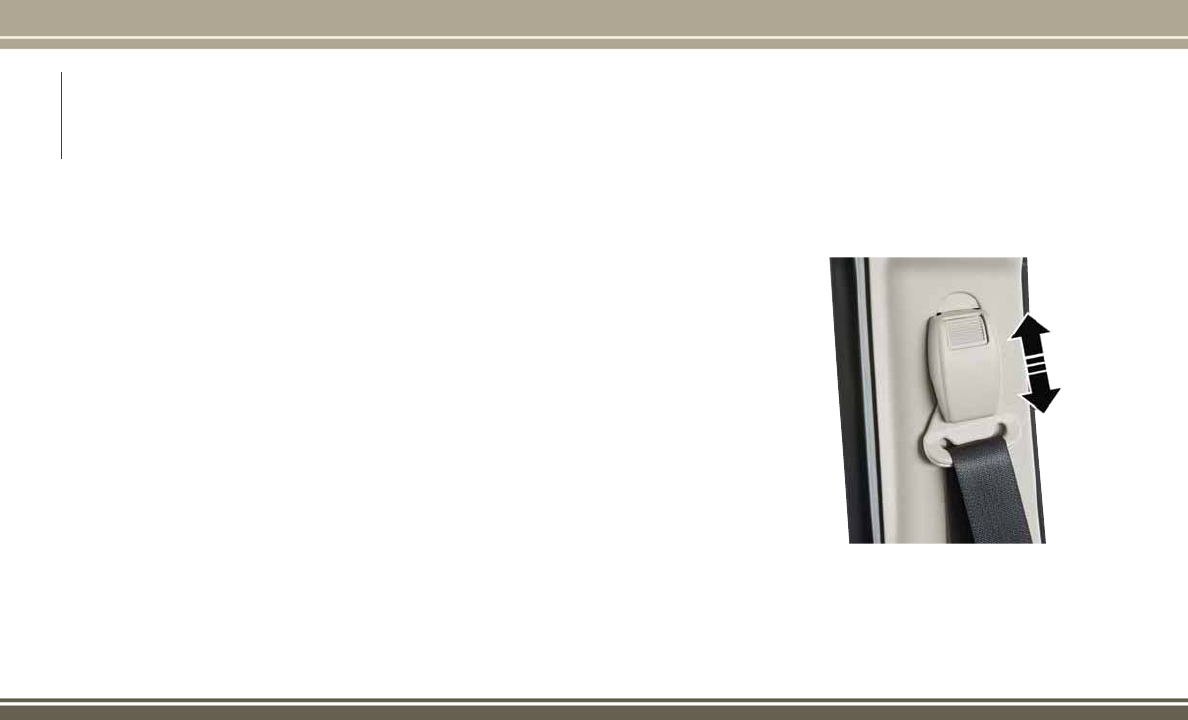
4. Position the lap belt so that it is snug and
lies low across your hips, below your ab-
domen. To remove slack in the lap belt
portion, pull up on the shoulder belt. To
loosen the lap belt if it is too tight, tilt the
latch plate and pull on the lap belt. A snug
seat belt reduces the risk of sliding under
the seat belt in a collision.
5. Position the shoulder belt across the
shoulder and chest with minimal, if any
slack so that it is comfortable and not
resting on your neck. The retractor will
withdraw any slack in the shoulder belt.
6. To release the seat belt, push the red
button on the buckle. The seat belt will
automatically retract to its stowed posi-
tion. If necessary, slide the latch plate
down the webbing to allow the seat belt to
retract fully.
Lap/Shoulder Belt Untwisting Procedure
Use the following procedure to untwist a
twisted lap/shoulder belt.
1. Position the latch plate as close as pos-
sible to the anchor point.
2. At about 6 to 12 inches (15 to 30 cm)
above the latch plate, grasp and twist the
seat belt webbing 180 degrees to create a
fold that begins immediately above the
latch plate.
3. Slide the latch plate upward over the
folded webbing. The folded webbing must
enter the slot at the top of the latch plate.
4. Continue to slide the latch plate up until it
clears the folded webbing and the seat
belt is no longer twisted.
Adjustable Upper Shoulder Belt Anchorage
In the driver and front passenger seats, the
top of the shoulder belt can be adjusted
upward or downward to position the seat belt
away from your neck. Push or squeeze the
anchorage button to release the anchorage,
and move it up or down to the position that
serves you best.
Adjustable Upper Shoulder Belt
Anchorage
SAFETY
88

As a guide, if you are shorter than average,
you will prefer the shoulder belt anchorage in
a lower position, and if you are taller than
average, you will prefer the shoulder belt
anchorage in a higher position. After you
release the anchorage button, try to move it
up or down to make sure that it is locked in
position.
NOTE:
The adjustable upper shoulder belt anchor-
age is equipped with an Easy Up feature. This
feature allows the shoulder belt anchorage to
be adjusted in the upward position without
pushing or squeezing the release button. To
verify the shoulder belt anchorage is latched,
pull downward on the shoulder belt anchor-
age until it is locked into position.
WARNING!
• Wearing your seat belt incorrectly could
make your injuries in a collision much
worse. You might suffer internal injuries,
or you could even slide out of the seat
belt. Follow these instructions to wear
WARNING!
your seat belt safely and to keep your
passengers safe, too.
• Position the shoulder belt across the
shoulder and chest with minimal, if any
slack so that it is comfortable and not
resting on your neck. The retractor will
withdraw any slack in the shoulder belt.
• Misadjustment of the seat belt could
reduce the effectiveness of the safety
belt in a crash.
Second Row Center Seat Belt Operating
Instructions
The second row center seat belt features a
seat belt with a mini-latch plate and buckle,
which allows the seat belt to detach from the
lower anchor when the seat is folded. The
mini-latch plate and regular latch plate can
then be stored out of the way in the right side
trim panel for added convenience to open up
utilization of the storage areas behind the
front seats when the seat is not occupied.
1. Remove the mini-latch plate and regular
latch plate from its stowed position in the
right rear side trim panel.
2. Grasp the mini-latch plate and pull the
seat belt over the seat.
3. Route the shoulder belt to the inside of
the right head restraint.
Mini-Latch Stowage
89

4. When the seat belt is long enough to fit,
insert the mini-latch plate into the mini-
buckle until you hear a “click.”
5.
Sit back in seat. Slide the regular latch plate
up the webbing as far as necessary to allow
the seat belt to go around your lap.
6. When the seat belt is long enough to fit,
insert the latch plate into the buckle until
you hear a “click.”
7. Position the lap belt so that it is snug and
lies low across your hips, below your ab-
domen. To remove slack in the lap belt
portion, pull up on the shoulder belt. To
loosen the lap belt if it is too tight, pull on
the lap belt. A snug seat belt reduces the
risk of sliding under the seat belt in a
collision.
8. Position the shoulder belt on your chest so
that it is comfortable and not resting on
your neck. The retractor will withdraw any
slack in the seat belt.
9. To release the seat belt, push the red
button on the buckle.
10. To disengage the mini-latch plate from
the mini-buckle for storage, insert the
regular latch plate into the black button
on the top of the mini-buckle. The seat
belt will automatically retract to its
stowed position. If necessary, slide the
latch plate down the webbing to allow
the seat belt to retract fully. Insert the
mini-latch plate and regular latch plate
into its stowed position.
Mini-Latch Plate Buckled
Rear Center Seat Belt Buckled
Detaching Mini-Latch And Buckle
SAFETY
90
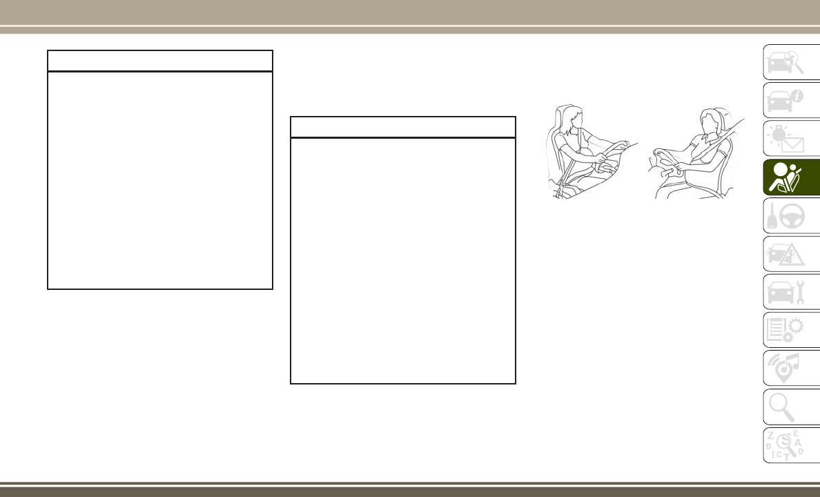
WARNING!
• If the mini-latch plate and mini-buckle
are not properly connected when the
seat belt is used by an occupant, the
seat belt will not be able to provide
proper restraint and will increase the risk
of injury in a collision.
• When reattaching the mini-latch plate
and mini-buckle, ensure the seat belt
webbing is not twisted. If the webbing is
twisted, follow the preceding procedure
to detach the mini-latch plate and mini-
buckle, untwist the webbing, and reat-
tach the mini-latch plate and mini-
buckle.
Seat Belt Extender
If a seat belt is not long enough to fit properly,
even when the webbing is fully extended and
the adjustable upper shoulder belt anchorage
(if equipped) is in its lowest position, your
authorized dealer can provide you with a Seat
Belt Extender. The Seat Belt Extender should
be used only if the existing seat belt is not
long enough. When the Seat Belt Extender is
not required for a different occupant, it must
be removed.
WARNING!
• ONLY use a Seat Belt Extender if it is
physically required in order to properly
fit the original seat belt system. DO NOT
USE the Seat Belt Extender if, when
worn, the distance between the front
edge of the Seat Belt Extender buckle
and the center of the occupant’s body is
LESS than 6 inches.
• Using a Seat Belt Extender when not
needed can increase the risk of serious
injury or death in a collision. Only use
the Seat Belt Extender when the lap belt
is not long enough and only use in the
recommended seating positions. Re-
move and store the Seat Belt Extender
when not needed.
Seat Belts And Pregnant Women
Seat belts must be worn by all occupants
including pregnant women: the risk of injury
in the event of an accident is reduced for the
mother and the unborn child if they are wear-
ing a seat belt.
Position the lap belt snug and low below the
abdomen and across the strong bones of the
hips. Place the shoulder belt across the chest
and away from the neck. Never place the
shoulder belt behind the back or under the
arm.
Pregnant Women And Seat Belts
91
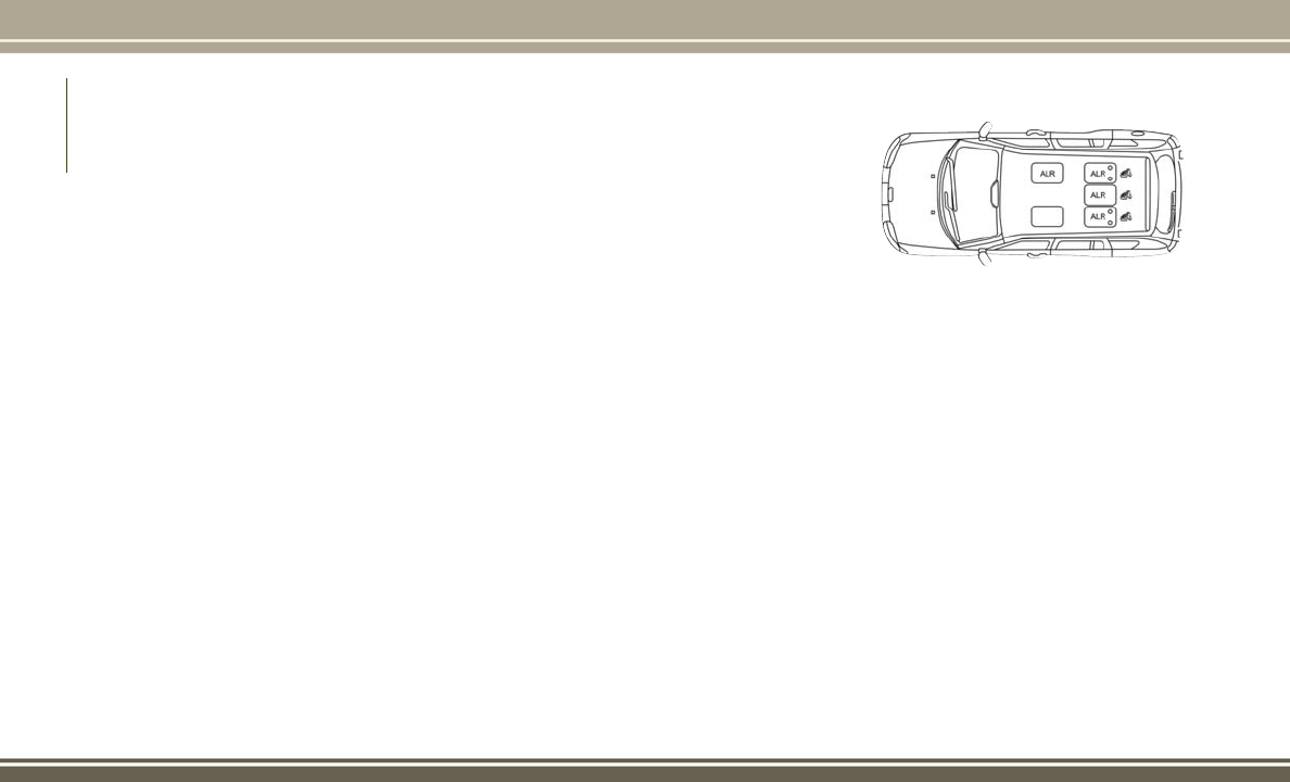
Seat Belt Pretensioner
The front seat belt system is equipped with
pretensioning devices that are designed to
remove slack from the seat belt in the event
of a collision. These devices may improve the
performance of the seat belt by removing
slack from the seat belt early in a collision.
Pretensioners work for all size occupants,
including those in child restraints.
NOTE:
These devices are not a substitute for proper
seat belt placement by the occupant. The
seat belt still must be worn snugly and posi-
tioned properly.
The pretensioners are triggered by the Occu-
pant Restraint Controller (ORC). Like the air
bags, the pretensioners are single use items.
A deployed pretensioner or a deployed air bag
must be replaced immediately.
Energy Management Feature
This vehicle has a seat belt system with an
Energy Management feature in the front seat-
ing positions that may help further reduce the
risk of injury in the event of a collision. The
seat belt system has a retractor assembly that
is designed to release webbing in a controlled
manner.
Switchable Automatic Locking Retractor
(ALR)
The seat belts in the passenger seating posi-
tions are equipped with a Switchable Auto-
matic Locking Retractor (ALR) which is used
to secure a child restraint system. For addi-
tional information, refer to “Installing Child
Restraints Using The Vehicle Seat Belt” un-
der the “Child Restraints” section of this
manual. The figure below illustrates the lock-
ing feature for each seating position.
If the passenger seating position is equipped
with an ALR and is being used for normal
usage, only pull the seat belt webbing out far
enough to comfortably wrap around the occu-
pant’s mid-section so as to not activate the
ALR. If the ALR is activated, you will hear a
clicking sound as the seat belt retracts. Allow
the webbing to retract completely in this case
and then carefully pull out only the amount of
webbing necessary to comfortably wrap
around the occupant’s mid-section. Slide the
latch plate into the buckle until you hear a
"click."
ALR — Switchable Automatic Locking
Retractor
SAFETY
92

In Automatic Locking Mode, the shoulder
belt is automatically pre-locked. The seat
belt will still retract to remove any slack in the
shoulder belt. Use the Automatic Locking
Mode anytime a child restraint is installed in
a seating position that has a seat belt with
this feature. Children 12 years old and under
should always be properly restrained in a
vehicle with a rear seat.
WARNING!
• Never place a rear-facing child restraint
in front of an air bag. A deploying pas-
senger front air bag can cause death or
serious injury to a child 12 years or
younger, including a child in a rear-
facing child restraint.
• Only use a rear-facing child restraint in a
vehicle with a rear seat.
How To Engage The Automatic Locking Mode
1. Buckle the combination lap and shoulder
belt.
2. Grasp the shoulder portion and pull down-
ward until the entire seat belt is extracted.
3. Allow the seat belt to retract. As the seat
belt retracts, you will hear a clicking
sound. This indicates the seat belt is now
in the Automatic Locking Mode.
How To Disengage The Automatic Locking Mode
Unbuckle the combination lap/shoulder belt
and allow it to retract completely to disen-
gage the Automatic Locking Mode and acti-
vate the vehicle sensitive (emergency) lock-
ing mode.
WARNING!
• The seat belt assembly must be replaced
if the switchable Automatic Locking Re-
tractor (ALR) feature or any other seat
belt function is not working properly
when checked according to the proce-
dures in the Service Manual.
• Failure to replace the seat belt assembly
could increase the risk of injury in colli-
sions.
• Do not use the Automatic Locking Mode
to restrain occupants who are wearing
the seat belt or children who are using
booster seats. The locked mode is only
WARNING!
used to install rear-facing or forward-
facing child restraints that have a har-
ness for restraining the child.
Supplemental Active Head Restraints (AHR)
These head restraints are passive, deployable
components, and vehicles with this equip-
ment cannot be readily identified by any
markings, only through visual inspection of
the head restraint. The head restraint will be
split in two halves, with the front half being
soft foam and trim, the back half being deco-
rative plastic.
How The Active Head Restraints (AHR) Work
The Occupant Restraint Controller (ORC) de-
termines whether the severity or type of rear
impact will require the Active Head Re-
straints (AHR) to deploy. If a rear impact
requires deployment, both the driver and
front passenger seat AHRs will be deployed.
When AHRs deploy during a rear impact, the
front half of the head restraint extends for-
ward to minimize the gap between the back of
the occupant’s head and the AHR. This sys-
93

tem is designed to help prevent or reduce the
extent of injuries to the driver and front
passenger in certain types of rear impacts.
NOTE:
The Active Head Restraints (AHR) may or
may not deploy in the event of a front or side
impact. However, if during a front impact, a
secondary rear impact occurs, the AHR may
deploy based on the severity and type of the
impact.
Active Head Restraint (AHR) Components:
WARNING!
• All occupants, including the driver,
should not operate a vehicle or sit in a
vehicle’s seat until the head restraints
are placed in their proper positions in
order to minimize the risk of neck injury
in the event of a collision.
• Do not place items over the top of the
Active Head Restraint, such as coats,
seat covers or portable DVD players.
These items may interfere with the op-
eration of the Active Head Restraint in
the event of a collision and could result
in serious injury or death.
• Active Head Restraints may be deployed
if they are struck by an object such as a
hand, foot or loose cargo. To avoid acci-
dental deployment of the Active Head
Restraint ensure that all cargo is se-
cured, as loose cargo could contact the
Active Head Restraint during sudden
stops. Failure to follow this warning
could cause personal injury if the Active
Head Restraint is deployed.
Active Head Restraint (AHR) Components
1 — Head Restraint Front Half (Soft
Foam And Trim)
2 — Head Restraint Back Half (Decora-
tive Plastic Rear Cover)
3 — Head Restraint Guide Tubes
4 — Seatback
SAFETY
94

NOTE:
For more information on properly adjusting
and positioning the head restraint, refer to
“Supplemental Active Head Restraints —
Front Seats” in “Getting To Know Your Ve-
hicle.”
Resetting Active Head Restraints (AHR)
If the Active Head Restraints are triggered
during a collision, the front half of the head
restraint will be extended forward and sepa-
rated from the rear half of the head restraint
(See Image). Do not drive your vehicle after
the AHRs have deployed. The head restraint
must be reset into the original position to best
protect the occupant for all types of colli-
sions. An authorized FCA US LLC dealer must
reset the AHRs on the driver’s and front
passenger’s seat before driving. Personally
attempting to reset the AHRs may result in
damage to the AHRs that could impair their
function.
WARNING!
Deployed AHRs are not able to best protect
you in all types of collisions. Have de-
ployed AHRs reset by an authorized dealer
immediately.
Supplemental Restraint Systems (SRS)
Some of the safety features described in this
section may be standard equipment on some
models, or may be optional equipment on
others. If you are not sure, ask your autho-
rized dealer.
The air bag system must be ready to protect
you in a collision. The Occupant Restraint
Controller (ORC) monitors the internal cir-
cuits and interconnecting wiring associated
with the electrical Air Bag System Compo-
nents. Your vehicle may be equipped with the
following Air Bag System Components:
Air Bag System Components
• Occupant Restraint Controller (ORC)
• Air Bag Warning Light
• Steering Wheel and Column
• Instrument Panel
• Knee Impact Bolsters
• Driver and Front Passenger Air Bags
• Supplemental Side Air Bags
• Front and Side Impact Sensors
• Seat Belt Pretensioners
• Seat Track Position Sensors
• Seat Belt Buckle Switch
Air Bag Warning Light
The ORC monitors the readiness of the
electronic parts of the air bag system when-
ever the ignition switch is in the START or
Active Head Restraint (AHR) Triggered
95

ON/RUN position. If the ignition switch is in
the OFF position or in the ACC position, the
air bag system is not on and the air bags will
not inflate.
The ORC contains a backup power supply
system that may deploy the air bag system
even if the battery loses power or it becomes
disconnected prior to deployment.
The ORC turns on the Air Bag Warning Light
in the instrument panel for approximately
four to eight seconds for a self-check when
the ignition switch is first in the ON/RUN
position. After the self-check, the Air Bag
Warning Light will turn off. If the ORC detects
a malfunction in any part of the system, it
turns on the Air Bag Warning Light, either
momentarily or continuously. A single chime
will sound to alert you if the light comes on
again after initial startup.
The ORC also includes diagnostics that will
illuminate the instrument panel Air Bag
Warning Light if a malfunction is detected
that could affect the air bag system. The
diagnostics also record the nature of the
malfunction. While the air bag system is
designed to be maintenance free, if any of
the following occurs, have an authorized
dealer service the air bag system immedi-
ately.
• The Air Bag Warning Light does not come
on during the four to eight seconds when
the ignition switch is first in the ON/RUN
position.
• The Air Bag Warning Light remains on
after the four to eight-second interval.
• The Air Bag Warning Light comes on inter-
mittently or remains on while driving.
NOTE:
If the speedometer, tachometer, or any en-
gine related gauges are not working, the Oc-
cupant Restraint Controller (ORC) may also
be disabled. In this condition the air bags
may not be ready to inflate for your protec-
tion. Have an authorized dealer service the
air bag system immediately.
WARNING!
Ignoring the Air Bag Warning Light in your
instrument panel could mean you won’t
have the air bag system to protect you in a
WARNING!
collision. If the light does not come on as a
bulb check when the ignition is first
turned on, stays on after you start the
vehicle, or if it comes on as you drive, have
an authorized dealer service the air bag
system immediately.
Front Air Bags
This vehicle has front air bags and lap/
shoulder belts for both the driver and front
passenger. The front air bags are a supple-
ment to the seat belt restraint systems. The
driver front air bag is mounted in the center
of the steering wheel. The passenger front air
bag is mounted in the instrument panel,
above the glove compartment. The words
“SRS AIRBAG” or “AIRBAG” are embossed
on the air bag covers.
SAFETY
96

WARNING!
• Being too close to the steering wheel or
instrument panel during front air bag
deployment could cause serious injury,
WARNING!
including death. Air bags need room to
inflate. Sit back, comfortably extending
your arms to reach the steering wheel or
instrument panel.
• Never place a rear-facing child restraint
in front of an air bag. A deploying pas-
senger front air bag can cause death or
serious injury to a child 12 years or
younger, including a child in a rear-
facing child restraint.
• Only use a rear-facing child restraint in a
vehicle with a rear seat.
Driver And Passenger Front Air Bag Features
The Advanced Front Air Bag system has mul-
tistage driver and front passenger air bags.
This system provides output appropriate to
the severity and type of collision as deter-
mined by the Occupant Restraint Controller
(ORC), which may receive information from
the front impact sensors (if equipped) or
other system components.
The first stage inflator is triggered immedi-
ately during an impact that requires air bag
deployment. A low energy output is used in
less severe collisions. A higher energy output
is used for more severe collisions.
This vehicle may be equipped with a driver
and/or front passenger seat belt buckle
switch that detects whether the driver or front
passenger seat belt is buckled. The seat belt
buckle switch may adjust the inflation rate of
the Advanced Front Air Bags.
This vehicle may be equipped with driver
and/or front passenger seat track position
sensors that may adjust the inflation rate of
the Advanced Front Air Bags based upon seat
position.
WARNING!
• No objects should be placed over or near
the air bag on the instrument panel or
steering wheel because any such objects
could cause harm if the vehicle is in a
collision severe enough to cause the air
bag to inflate.
Front Air Bag And Knee Impact Bolster
Locations
1—
Driver And Passenger Front Air Bags
2 — Passenger Knee Impact Bolster
3 — Driver Knee Impact Bolster
97

WARNING!
• Do not put anything on or around the air
bag covers or attempt to open them
manually. You may damage the air bags
and you could be injured because the air
bags may no longer be functional. The
protective covers for the air bag cushions
are designed to open only when the air
bags are inflating.
• Relying on the air bags alone could lead
to more severe injuries in a collision. The
air bags work with your seat belt to
restrain you properly. In some collisions,
air bags won’t deploy at all. Always wear
your seat belts even though you have air
bags.
Front Air Bag Operation
Front Air Bags are designed to provide addi-
tional protection by supplementing the seat
belts. Front air bags are not expected to
reduce the risk of injury in rear, side, or
rollover collisions. The front air bags will not
deploy in all frontal collisions, including
some that may produce substantial vehicle
damage — for example, some pole collisions,
truck underrides, and angle offset collisions.
On the other hand, depending on the type
and location of impact, front air bags may
deploy in crashes with little vehicle front-end
damage but that produce a severe initial
deceleration.
Because air bag sensors measure vehicle
deceleration over time, vehicle speed and
damage by themselves are not good indica-
tors of whether or not an air bag should have
deployed.
Seat belts are necessary for your protection in
all collisions, and also are needed to help
keep you in position, away from an inflating
air bag.
When the ORC detects a collision requiring
the front air bags, it signals the inflator units.
A large quantity of non-toxic gas is generated
to inflate the front air bags.
The steering wheel hub trim cover and the
upper right side of the instrument panel
separate and fold out of the way as the air
bags inflate to their full size. The front air
bags fully inflate in less time than it takes to
blink your eyes. The front air bags then
quickly deflate while helping to restrain the
driver and front passenger.
Knee Impact Bolsters
The Knee Impact Bolsters help protect the
knees of the driver and front passenger, and
position the front occupants for improved
interaction with the front air bags.
WARNING!
• Do not drill, cut, or tamper with the knee
impact bolsters in any way.
• Do not mount any accessories to the
knee impact bolsters such as alarm
lights, stereos, citizen band radios, etc.
Supplemental Side Air Bags
Your vehicle is equipped with two types of
side air bags:
1. Supplemental Seat-Mounted Side Air Bags
(SABs): Located in the outboard side of the
front seats. The SABs are marked with a
“SRS AIRBAG” or “AIRBAG” label sewn into
the outboard side of the seats.
SAFETY
98

The SABs may help to reduce the risk of
occupant injury during certain side im-
pacts and/or vehicle rollover events, in
addition to the injury reduction potential
provided by the seat belts and body struc-
ture.
When the SAB deploys, it opens the seam
on the outboard side of the seatback’s
trim cover. The inflating SAB deploys
through the seat seam into the space
between the occupant and the door. The
SAB moves at a very high speed and with
such a high force that it could injure
occupants if they are not seated properly,
or if items are positioned in the area
where the SAB inflates. Children are at an
even greater risk of injury from a deploy-
ing air bag.
WARNING!
Do not use accessory seat covers or place
objects between you and the Side Air
Bags; the performance could be adversely
affected and/or objects could be pushed
into you, causing serious injury.
2. Supplemental Side Air Bag Inflatable Cur-
tains (SABICs): Located above the side win-
dows. The trim covering the SABICs is la-
beled “SRS AIRBAG” or “AIRBAG.”
SABICs may help reduce the risk of head
or other injuries to front and rear seat
outboard occupants in certain side im-
pacts and/or vehicle rollover events, in
addition to the injury reduction potential
provided by the seat belts and body struc-
ture.
The SABICs deploy downward, covering
the side windows. An inflating SABIC
pushes the outside edge of the trim out of
Supplemental Seat-Mounted Side Air Bag
Label
Supplemental Side Air Bag Inflatable Cur-
tain (SABIC) Label Location
99

the way and covers the window. The
SABICs inflate with enough force to in-
jure occupants if they are not belted and
seated properly, or if items are positioned
in the area where the SABICs inflate.
Children are at an even greater risk of
injury from a deploying air bag.
WARNING!
• Do not stack luggage or other cargo up
high enough to block the deployment of
the SABICs. The trim covering above the
side windows where the SABIC and its
deployment path are located should re-
main free from any obstructions.
• In order for the SABICs to work as in-
tended, do not install any accessory
items in your vehicle which could alter
the roof. Do not add an aftermarket
sunroof to your vehicle. Do not add roof
racks that require permanent attach-
ments (bolts or screws) for installation
on the vehicle roof. Do not drill into the
roof of the vehicle for any reason.
The SABICs and SABs (Side Air Bags) are
designed to activate in certain side impacts
and certain rollover events. The Occupant
Restraint Controller (ORC) determines
whether the deployment of the Side Air Bags
in a particular side impact or rollover event is
appropriate, based on the severity and type of
collision. Vehicle damage by itself is not a
good indicator of whether or not Side Air Bags
should have deployed.
Side Air Bags are a supplement to the seat
belt restraint system. Side Air Bags deploy in
less time than it takes to blink your eyes.
WARNING!
• Occupants, including children, who are
up against or very close to Side Air Bags
can be seriously injured or killed. Occu-
pants, including children, should never
lean on or sleep against the door, side
windows, or area where the side air bags
inflate, even if they are in an infant or
child restraint.
• Seat belts (and child restraints where
appropriate) are necessary for your pro-
WARNING!
tection in all collisions. They also help
keep you in position, away from an in-
flating Side Air Bag. To get the best
protection from the Side Air Bags, occu-
pants must wear their seat belts properly
and sit upright with their backs against
the seats. Children must be properly
restrained in a child restraint or booster
seat that is appropriate for the size of the
child.
• Side Air Bags need room to inflate. Do
not lean against the door or window. Sit
upright in the center of the seat.
• Being too close to the Side Air Bags
during deployment could cause you to
be severely injured or killed.
• Relying on the Side Air Bags alone could
lead to more severe injuries in a colli-
sion. The Side Air Bags work with your
seat belt to restrain you properly. In
some collisions, Side Air Bags won’t
deploy at all. Always wear your seat belt
even though you have Side Air Bags.
SAFETY
100

NOTE:
Air bag covers may not be obvious in the
interior trim, but they will open during air bag
deployment.
Side Impacts
In side impacts, the side impact sensors aid
the ORC in determining the appropriate re-
sponse to impact events. The system is cali-
brated to deploy the Side Air Bags on the
impact side of the vehicle during impacts
that require Side Air Bag occupant protec-
tion. In side impacts, the Side Air Bags de-
ploy independently; a left side impact de-
ploys the left Side Air Bags only and a right
side impact deploys the right Side Air Bags
only.
The Side Air Bags will not deploy in all side
collisions, including some collisions at cer-
tain angles, or some side collisions that do
not impact the area of the passenger com-
partment. The Side Air Bags may deploy
during angled or offset frontal collisions
where the front air bags deploy.
Rollover Events
Side Air Bags are designed to activate in
certain rollover events. The ORC determines
whether the deployment of the Side Air Bags
in a particular rollover event is appropriate,
based on the severity and type of collision.
Vehicle damage by itself is not a good indica-
tor of whether or not Side Air Bags should
have deployed.
The Side Air Bags will not deploy in all
rollover events. The rollover sensing-system
determines if a rollover event may be in
progress and whether deployment is appro-
priate. A slower-developing event may deploy
the seat belt pretensioners on both sides of
the vehicle. A faster-developing event may
deploy the seat belt pretensioners as well as
the Side Air Bags on both sides of the vehicle.
The rollover sensing-system may also deploy
the seat belt pretensioners, with or without
the Side Air Bags, on both sides of the vehicle
if the vehicle experiences a near rollover
event.
The SABICs may help reduce the risk of
partial or complete ejection of vehicle occu-
pants through side windows in certain roll-
over or side impact events.
The Occupant Restraint Controller (ORC)
monitors the internal circuits and intercon-
necting wiring associated with electrical Air
Bag System Components listed below:
Air Bag System Components
• Occupant Restraint Controller (ORC)
• Air Bag Warning Light
• Steering Wheel and Column
• Instrument Panel
• Knee Impact Bolsters
• Driver and Front Passenger Air Bags
• Supplemental Side Air Bags
• Front and Side Impact Sensors
• Seat Belt Pretensioners
• Seat Track Position Sensors
• Seat Belt Buckle Switch
101

If A Deployment Occurs
The front air bags are designed to deflate
immediately after deployment.
NOTE:
Front and/or side air bags will not deploy in
all collisions. This does not mean something
is wrong with the air bag system.
If you do have a collision which deploys the
air bags, any or all of the following may occur:
• The air bag material may sometimes cause
abrasions and/or skin reddening to the
occupants as the air bags deploy and un-
fold. The abrasions are similar to friction
rope burns or those you might get sliding
along a carpet or gymnasium floor. They
are not caused by contact with chemicals.
They are not permanent and normally heal
quickly. However, if you haven’t healed
significantly within a few days, or if you
have any blistering, see your doctor imme-
diately.
• As the air bags deflate, you may see some
smoke-like particles. The particles are a
normal by-product of the process that gen-
erates the non-toxic gas used for air bag
inflation. These airborne particles may ir-
ritate the skin, eyes, nose, or throat. If you
have skin or eye irritation, rinse the area
with cool water. For nose or throat irrita-
tion, move to fresh air. If the irritation
continues, see your doctor. If these par-
ticles settle on your clothing, follow the
garment manufacturer’s instructions for
cleaning.
Do not drive your vehicle after the air bags
have deployed. If you are involved in another
collision, the air bags will not be in place to
protect you.
WARNING!
Deployed air bags and seat belt preten-
sioners cannot protect you in another col-
lision. Have the air bags, seat belt preten-
sioners, and the seat belt retractor
assemblies replaced by an authorized
dealer immediately. Also, have the Occu-
pant Restraint Controller System serviced
as well.
NOTE:
• Air bag covers may not be obvious in the
interior trim, but they will open during air
bag deployment.
• After any collision, the vehicle should be
taken to an authorized dealer
immediately.
Enhanced Accident Response System
In the event of an impact, if the communica-
tion network remains intact, and the power
remains intact, depending on the nature of
the event, the ORC will determine whether to
have the Enhanced Accident Response Sys-
tem perform the following functions:
• Cut off fuel to the engine.
• Flash hazard lights as long as the battery
has power or until the hazard light button
is pressed. The hazard lights can be deac-
tivated by pressing the hazard light but-
ton.
• Turn on the interior lights, which remain
on as long as the battery has power.
• Unlock the power door locks.
SAFETY
102

Enhanced Accident Response System Reset
Procedure
In order to reset the Enhanced Accident Re-
sponse System functions after an event, the
ignition switch must be changed from igni-
tion START or ON/RUN to ignition OFF. Care-
fully check the vehicle for fuel leaks in the
engine compartment and on the ground near
the engine compartment and fuel tank before
resetting the system and starting the engine.
Maintaining Your Air Bag System
WARNING!
• Modifications to any part of the air bag
system could cause it to fail when you
need it. You could be injured if the air
bag system is not there to protect you.
Do not modify the components or wiring,
including adding any kind of badges or
stickers to the steering wheel hub trim
cover or the upper right side of the in-
strument panel. Do not modify the front
bumper, vehicle body structure, or add
aftermarket side steps or running
boards.
WARNING!
• It is dangerous to try to repair any part of
the air bag system yourself. Be sure to
tell anyone who works on your vehicle
that it has an air bag system.
• Do not attempt to modify any part of your
air bag system. The air bag may inflate
accidentally or may not function prop-
erly if modifications are made. Take your
vehicle to an authorized dealer for any
air bag system service. If your seat, in-
cluding your trim cover and cushion,
needs to be serviced in any way (includ-
ing removal or loosening/tightening of
seat attachment bolts), take the vehicle
to your authorized dealer. Only manufac-
turer approved seat accessories may be
used. If it is necessary to modify the air
bag system for persons with disabilities,
contact your authorized dealer.
Event Data Recorder (EDR)
This vehicle is equipped with an event data
recorder (EDR). The main purpose of an EDR
is to record, in certain crash or near crash-like
situations, such as an air bag deployment or
hitting a road obstacle, data that will assist in
understanding how a vehicle’s systems per-
formed. The EDR is designed to record data
related to vehicle dynamics and safety sys-
tems for a short period of time, typically
30 seconds or less. The EDR in this vehicle is
designed to record such data as:
• How various systems in your vehicle were
operating;
• Whether or not the driver and passenger
safety belts were buckled/fastened;
• How far (if at all) the driver was depressing
the accelerator and/or brake pedal; and,
• How fast the vehicle was traveling.
• These data can help provide a better un-
derstanding of the circumstances in which
crashes and injuries occur.
103

NOTE:
EDR data are recorded by your vehicle only if
a non-trivial crash situation occurs; no data
are recorded by the EDR under normal driving
conditions and no personal data (e.g., name,
gender, age, and crash location) are re-
corded. However, other parties, such as law
enforcement, could combine the EDR data
with the type of personally identifying data
routinely acquired during a crash investiga-
tion.
To read data recorded by an EDR, special
equipment is required, and access to the
vehicle or the EDR is needed. In addition to
the vehicle manufacturer, other parties, such
as law enforcement, that have the special
equipment, can read the information if they
have access to the vehicle or the EDR.
Child Restraints
Everyone in your vehicle needs to be buckled
up at all times, including babies and chil-
dren. Every state in the United States, and
every Canadian province, requires that small
children ride in proper restraint systems. This
is the law, and you can be prosecuted for
ignoring it.
Children 12 years or younger should ride
properly buckled up in a rear seat, if avail-
able. According to crash statistics, children
are safer when properly restrained in the rear
seats rather than in the front.
WARNING!
In a collision, an unrestrained child can
become a projectile inside the vehicle.
The force required to hold even an infant
on your lap could become so great that you
could not hold the child, no matter how
strong you are. The child and others could
be badly injured. Any child riding in your
vehicle should be in a proper restraint for
the child’s size.
There are different sizes and types of re-
straints for children from newborn size to the
child almost large enough for an adult safety
belt. Always check the child seat Owner’s
Manual to make sure you have the correct
seat for your child. Carefully read and follow
all the instructions and warnings in the child
restraint Owner’s Manual and on all the la-
bels attached to the child restraint.
Before buying any restraint system, make
sure that it has a label certifying that it meets
all applicable Safety Standards. You should
also make sure that you can install it in the
vehicle where you will use it.
NOTE:
• For additional information, refer to
www.safercar.gov/parents/index.htm or
call: 1–888–327–4236
• Canadian residents should refer to Trans-
port Canada’s website for additional infor-
mation: http://www.tc.gc.ca/eng/
motorvehiclesafety/
safedrivers-childsafety-index-53.htm
SAFETY
104

Summary Of Recommendations For Restraining Children In Vehicles
Child Size, Height, Weight Or Age Recommended Type Of Child Restraint
Infants and Toddlers
Children who are two years old or younger and
who have not reached the height or weight lim-
its of their child restraint
Either an Infant Carrier or a Convertible Child
Restraint, facing rearward in the rear seat of
the vehicle
Small Children
Children who are at least two years old or who
have out-grown the height or weight limit of
their rear-facing child restraint
Forward-Facing Child Restraint with a five-
point Harness, facing forward in the rear seat
of the vehicle
Larger Children
Children who have out-grown their forward-
facing child restraint, but are too small to prop-
erly fit the vehicle’s seat belt
Belt Positioning Booster Seat and the vehicle
seat belt, seated in the rear seat of the vehicle
Children Too Large for Child Restraints
Children 12 years old or younger, who have
out-grown the height or weight limit of their
booster seat
Vehicle Seat Belt, seated in the rear seat of the
vehicle
Infant And Child Restraints
Safety experts recommend that children ride
rear-facing in the vehicle until they are two
years old or until they reach either the height
or weight limit of their rear-facing child re-
straint. Two types of child restraints can be
used rear-facing: infant carriers and convert-
ible child seats.
The infant carrier is only used rear-facing in
the vehicle. It is recommended for children
from birth until they reach the weight or
height limit of the infant carrier. Convertible
child seats can be used either rear-facing or
forward-facing in the vehicle. Convertible
child seats often have a higher weight limit in
the rear-facing direction than infant carriers
do, so they can be used rear-facing by chil-
dren who have outgrown their infant carrier
but are still less than at least two years old.
Children should remain rear-facing until they
reach the highest weight or height allowed by
their convertible child seat.
WARNING!
• Never place a rear-facing child restraint
in front of an air bag. A deploying pas-
senger front air bag can cause death or
serious injury to a child 12 years or
younger, including a child in a rear-
facing child restraint.
• Only use a rear-facing child restraint in a
vehicle with a rear seat.
105

Older Children And Child Restraints
Children who are two years old or who have
outgrown their rear-facing convertible child
seat can ride forward-facing in the vehicle.
Forward-facing child seats and convertible
child seats used in the forward-facing direc-
tion are for children who are over two years
old or who have outgrown the rear-facing
weight or height limit of their rear-facing
convertible child seat. Children should re-
main in a forward-facing child seat with a
harness for as long as possible, up to the
highest weight or height allowed by the child
seat.
All children whose weight or height is above
the forward-facing limit for the child seat
should use a belt-positioning booster seat
until the vehicle’s seat belts fit properly. If
the child cannot sit with knees bent over the
vehicle’s seat cushion while the child’s back
is against the seatback, they should use a
belt-positioning booster seat. The child and
belt-positioning booster seat are held in the
vehicle by the seat belt.
WARNING!
• Improper installation can lead to failure
of an infant or child restraint. It could
come loose in a collision. The child
could be badly injured or killed. Follow
the child restraint manufacturer’s direc-
tions exactly when installing an infant or
child restraint.
• After a child restraint is installed in the
vehicle, do not move the vehicle seat
forward or rearward because it can
loosen the child restraint attachments.
Remove the child restraint before ad-
justing the vehicle seat position. When
the vehicle seat has been adjusted, re-
install the child restraint.
• When your child restraint is not in use,
secure it in the vehicle with the seat belt
or LATCH anchorages, or remove it from
the vehicle. Do not leave it loose in the
vehicle. In a sudden stop or accident, it
could strike the occupants or seatbacks
and cause serious personal injury.
Children Too Large For Booster Seats
Children who are large enough to wear the
shoulder belt comfortably, and whose legs are
long enough to bend over the front of the seat
when their back is against the seatback,
should use the seat belt in a rear seat. Use
this simple 5-step test to decide whether the
child can use the vehicle’s seat belt alone:
1. Can the child sit all the way back against
the back of the vehicle seat?
2. Do the child’s knees bend comfortably
over the front of the vehicle seat – while
they are still sitting all the way back?
3. Does the shoulder belt cross the child’s
shoulder between their neck and arm?
4. Is the lap part of the belt as low as
possible, touching the child’s thighs and
not their stomach?
5. Can the child stay seated like this for the
whole trip?
If the answer to any of these questions was
“no,” then the child still needs to use a
booster seat in this vehicle. If the child is
using the lap/shoulder belt, check seat belt
fit periodically and make sure the seat belt
SAFETY
106
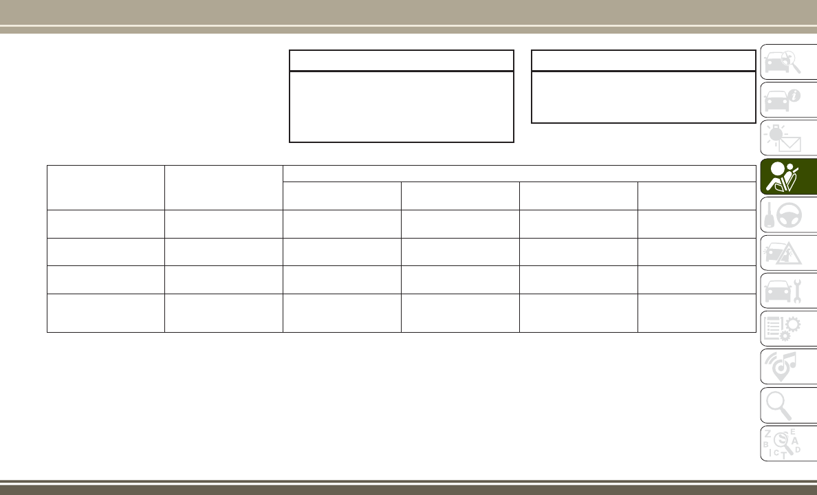
buckle is latched. A child’s squirming or
slouching can move the belt out of position. If
the shoulder belt contacts the face or neck,
move the child closer to the center of the
vehicle, or use a booster seat to position the
seat belt on the child correctly.
WARNING!
Never allow a child to put the shoulder belt
under an arm or behind their back. In a
crash, the shoulder belt will not protect a
child properly, which may result in serious
WARNING!
injury or death. A child must always wear
both the lap and shoulder portions of the
seat belt correctly.
Recommendations For Attaching Child Restraints
Restraint Type Combined Weight of the
Child + Child Restraint
Use any attachment method shown with an “X” Below
LATCH – Lower Anchors
Only
Seat Belt Only LATCH – Lower Anchors
+ Top Tether Anchor
Seat Belt + Top Tether
Anchor
Rear-Facing Child Re-
straint
Up to 65 lbs (29.5 kg)
XX
Rear-Facing Child Re-
straint
More than 65 lbs
(29.5 kg)
X
Forward-Facing Child
Restraint
Up to 65 lbs (29.5 kg) X X
Forward-Facing Child
Restraint
More than 65 lbs
(29.5 kg)
X
107

Lower Anchors And Tethers For CHildren
(LATCH) Restraint System
Your vehicle is equipped with the child re-
straint anchorage system called LATCH,
which stands for Lower Anchors and Tethers
for CHildren. The LATCH system has three
vehicle anchor points for installing LATCH-
equipped child seats. There are two lower
anchorages located at the back of the seat
cushion where it meets the seatback and one
top tether anchorage located behind the seat-
ing position. These anchorages are used to
install LATCH-equipped child seats without
using the vehicle’s seat belts. Some seating
positions may have a top tether anchorage
but no lower anchorages. In these seating
positions, the seat belt must be used with the
top tether anchorage to install the child re-
straint. Please see the following table for
more information.
Latch Positions For Installing Child Re-
straints In This Vehicle
LATCH Label
LATCH Positions
Lower Anchorage Symbol (2 An-
chorages Per Seating Position)
Top Tether Anchorage Symbol
SAFETY
108

Frequently Asked Questions About Installing Child Restraints With LATCH
What is the weight limit (child’s weight +
weight of the child restraint) for using the
LATCH anchorage system to attach the child
restraint?
65 lbs (29.5 kg)
Use the LATCH anchorage system until the
combined weight of the child and the child
restraint is 65 lbs (29.5 kg). Use the seat belt
and tether anchor instead of the LATCH system
once the combined weight is more than 65 lbs
(29.5 kg).
Can the LATCH anchorages and the seat belt
be used together to attach a rear-facing or
forward-facing child restraint?
No
Do not use the seat belt when you use the
LATCH anchorage system to attach a rear-
facing or forward-facing child restraint.
Can a child seat be installed in the center posi-
tion using the inner LATCH lower anchorages?
Yes
You can install child restraints with flexible
lower anchors in the center position. The inner
anchorages are 15.5 inches (390 mm) apart.
Do not install child restraints with rigid lower
anchors in the center position.
Can two child restraints be attached using a
common lower LATCH anchorage?
No
Never “share” a LATCH anchorage with two or
more child restraints. If the center position
does not have dedicated LATCH lower anchor-
ages, use the seat belt to install a child seat in
the center position next to a child seat using
the LATCH anchorages in an outboard position.
Can the rear-facing child restraint touch the
back of the front passenger seat?
Yes
The child seat may touch the back of the front
passenger seat if the child restraint manufac-
turer also allows contact. See your child re-
straint owner’s manual for more information.
Can the head restraints be removed? No
109

Locating The LATCH Anchorages
The lower anchorages are round bars that are
found at the rear of the seat cushion where it
meets the seatback. They are just visible
when you lean into the rear seat to install the
child restraint. You will easily feel them if you
run your finger along the gap between the
seatback and seat cushion.
Locating The Upper Tether Anchorages
There are tether strap anchorages behind
each rear seating position located on the
back of the seat.
LATCH-compatible child restraint systems
will be equipped with a rigid bar or a flexible
strap on each side. Each will have a hook or
connector to attach to the lower anchorage
and a way to tighten the connection to the
anchorage. Forward-facing child restraints
and some rear-facing child restraints will also
be equipped with a tether strap. The tether
strap will have a hook at the end to attach to
the top tether anchorage and a way to tighten
the strap after it is attached to the anchorage.
Center Seat LATCH: Four Door
Do not install child restraints with rigid lower
attachments in the center seating position.
Only install this type of child restraint in the
outboard seating positions. Child restraints
with flexible, webbing mounted lower attach-
ments can be installed in any rear seating
position.
Lower LATCH Anchors
Rear Seat Tether Anchors
SAFETY
110

WARNING!
Never use the same lower anchorage to
attach more than one child restraint. If you
are installing LATCH-compatible child re-
straints next to each other, you must use
the seat belt for the center position. You
can then use either the LATCH anchors or
the vehicle’s seat belt for installing child
seats in the outboard positions. Please
refer to “Installing The LATCH-Compatible
Child Restraint System” for typical instal-
lation instructions.
Always follow the directions of the child re-
straint manufacturer when installing your child
restraint. Not all child restraint systems will be
installed as described here.
To Install A LATCH-Compatible Child Re-
straint
If the selected seating position has a Switch-
able Automatic Locking Retractor (ALR) seat
belt, stow the seat belt, following the instruc-
tions below. See the section “Installing Child
Restraints Using The Vehicle Seat Belt” to
check what type of seat belt each seating
position has.
1. Loosen the adjusters on the lower straps
and on the tether strap of the child seat so
that you can more easily attach the hooks
or connectors to the vehicle anchorages.
2. Place the child seat between the lower
anchorages for that seating position. For
some second row seats, you may need to
recline the seat and / or raise the head
restraint to get a better fit. If the rear seat
can be moved forward and rearward in the
vehicle, you may wish to move it to its
rear-most position to make room for the
child seat. You may also move the front
seat forward to allow more room for the
child seat.
3. Attach the lower hooks or connectors of
the child restraint to the lower anchorages
in the selected seating position.
4. If the child restraint has a tether strap,
connect it to the top tether anchorage.
See the section “Installing Child Re-
straints Using The Top Tether Anchorage”
for directions to attach a tether anchor.
5. Tighten all of the straps as you push the
child restraint rearward and downward
into the seat. Remove slack in the straps
according to the child restraint manufac-
turer’s instructions.
6. Test that the child restraint is installed
tightly by pulling back and forth on the
child seat at the belt path. It should not
move more than 1 inch (25.4 mm) in any
direction.
How To Stow An Unused Switchable-ALR
(ALR) Seat Belt
When using the LATCH attaching system to
install a child restraint, stow all ALR seat
belts that are not being used by other occu-
pants or being used to secure child restraints.
An unused belt could injure a child if they
play with it and accidentally lock the seat belt
retractor. Before installing a child restraint
using the LATCH system, buckle the seat belt
behind the child restraint and out of the
child’s reach. If the buckled seat belt inter-
feres with the child restraint installation, in-
stead of buckling it behind the child re-
straint, route the seat belt through the child
restraint belt path and then buckle it. Do not
111

lock the seat belt. Remind all children in the
vehicle that the seat belts are not toys and
that they should not play with them.
WARNING!
• Improper installation of a child restraint
to the LATCH anchorages can lead to
failure of the restraint. The child could
be badly injured or killed. Follow the
child restraint manufacturer’s directions
exactly when installing an infant or child
restraint.
• Child restraint anchorages are designed
to withstand only those loads imposed
by correctly-fitted child restraints. Un-
der no circumstances are they to be
used for adult seat belts, harnesses, or
for attaching other items or equipment
to the vehicle.
Installing Child Restraints Using The Ve-
hicle Seat Belt
Child restraint systems are designed to be
secured in vehicle seats by lap belts or the
lap belt portion of a lap/shoulder belt.
WARNING!
• Improper installation or failure to prop-
erly secure a child restraint can lead to
failure of the restraint. The child could
be badly injured or killed.
• Follow the child restraint manufactur-
er’s directions exactly when installing an
infant or child restraint.
The seat belts in the rear passenger seating
positions are equipped with a Switchable
Automatic Locking Retractor (ALR) that is
designed to keep the lap portion of the seat
belt tight around the child restraint so that it
is not necessary to use a locking clip. The
ALR retractor can be “switched” into a
locked mode by pulling all of the webbing out
of the retractor and then letting the webbing
retract back into the retractor. If it is locked,
the ALR will make a clicking noise while the
webbing is pulled back into the retractor.
Refer to the “Automatic Locking Mode” de-
scription in “Switchable Automatic Locking
Retractors (ALR)” under “Occupant Re-
straint Systems” for additional information
on ALR.
Please see the table below and the following
sections for more information.
Lap/Shoulder Belt Systems For Installing
Child Restraints In This Vehicle
ALR = Switchable Automatic Locking
Retractor
Top Tether Anchorage Symbol
SAFETY
112

Frequently Asked Questions About Installing Child Restraints With Seat Belts
What is the weight limit (child’s weight +
weight of the child restraint) for using the
Tether Anchor with the seat belt to attach a
forward facing child restraint?
Weight limit of the Child
Restraint
Always use the tether anchor when using the seat belt to install a
forward facing child restraint, up to the recommended weight limit
of the child restraint.
Can the rear-facing child restraint touch the
back of the front passenger seat?
Yes
Contact between the front passenger seat and the child restraint is
allowed, if the child restraint manufacturer also allows contact.
Can the head restraints be removed? No
Can the buckle stalk be twisted to tighten the
seat belt against the belt path of the child re-
straint?
No
Do not twist the buckle stalk in a seating position with an ALR re-
tractor.
Installing A Child Restraint With A Switch-
able Automatic Locking Retractor (ALR):
Child restraint systems are designed to be
secured in vehicle seats by lap belts or the lap
belt portion of a lap/shoulder belt.
WARNING!
• Improper installation or failure to prop-
erly secure a child restraint can lead to
failure of the restraint. The child could
be badly injured or killed.
WARNING!
• Follow the child restraint manufacturer’s
directions exactly when installing an in-
fant or child restraint.
1. Place the child seat in the center of the
seating position. For some second row
seats, you may need to recline the seat
and/or raise the head restraint to get a
better fit. If the rear seat can be moved
forward and rearward in the vehicle, you
may wish to move it to its rear-most posi-
tion to make room for the child seat. You
may also move the front seat forward to
allow more room for the child seat.
2. Pull enough of the seat belt webbing from
the retractor to pass it through the belt
path of the child restraint. Do not twist the
belt webbing in the belt path.
3. Slide the latch plate into the buckle until
you hear a “click.”
4. Pull on the webbing to make the lap
portion tight against the child seat.
5. To lock the seat belt, pull down on the
shoulder part of the belt until you have
113

pulled all the seat belt webbing out of the
retractor. Then, allow the webbing to re-
tract back into the retractor. As the web-
bing retracts, you will hear a clicking
sound. This means the seat belt is now in
the Automatic Locking mode.
6. Try to pull the webbing out of the retractor.
If it is locked, you should not be able to
pull out any webbing. If the retractor is
not locked, repeat step 5.
7. Finally, pull up on any excess webbing to
tighten the lap portion around the child
restraint while you push the child restraint
rearward and downward into the vehicle
seat.
8. If the child restraint has a top tether strap
and the seating position has a top tether
anchorage, connect the tether strap to the
anchorage and tighten the tether strap.
See the section “Installing Child Re-
straints Using the Top Tether Anchorage”
for directions to attach a tether anchor.
9. Test that the child restraint is installed
tightly by pulling back and forth on the
child seat at the belt path. It should not
move more than 1 inch (25.4 mm) in any
direction.
Any seat belt system will loosen with time, so
check the belt occasionally, and pull it tight if
necessary.
Installing Child Restraints Using the Top
Tether Anchorage
WARNING!
Do not attach a tether strap for a rear-
facing car seat to any location in front of
the car seat, including the seat frame or a
tether anchorage. Only attach the tether
strap of a rear-facing car seat to the tether
anchorage that is approved for that seating
position, located behind the top of the
vehicle seat. See the section “Lower An-
chors and Tethers for CHildren (LATCH)
Restraint System” for the location of ap-
proved tether anchorages in your vehicle.
WARNING!
1. Look behind the seating position where
you plan to install the child restraint to
find the tether anchorage. You may need
to move the seat forward to provide better
access to the tether anchorage. If there is
no top tether anchorage for that seating
position, move the child restraint to an-
other position in the vehicle if one is
available.
2. Route the tether strap to provide the most
direct path for the strap between the an-
chor and the child seat, routing it over the
center of the head restraint.
SAFETY
114

3. Attach the tether strap hook of the child
restraint to the top tether anchorage as
shown in the diagram.
4. Remove slack in the tether strap accord-
ing to the child restraint manufacturer’s
instructions.
WARNING!
• An incorrectly anchored tether strap
could lead to increased head motion and
possible injury to the child. Use only the
anchorage position directly behind the
child seat to secure a child restraint top
tether strap.
• If your vehicle is equipped with a split
rear seat, make sure the tether strap
does not slip into the opening between
the seatbacks as you remove slack in the
strap.
Transporting Pets
Air Bags deploying in the front seat could
harm your pet. An unrestrained pet will be
thrown about and possibly injured, or injure a
passenger during panic braking or in a colli-
sion.
Pets should be restrained in the rear seat in
pet harnesses or pet carriers that are secured
by seat belts.
SAFETY TIPS
Transporting Passengers
NEVER TRANSPORT PASSENGERS IN THE
CARGO AREA.
WARNING!
• Do not leave children or animals inside
parked vehicles in hot weather. Interior
heat build-up may cause serious injury
or death.
• It is extremely dangerous to ride in a
cargo area, inside or outside of a vehicle.
In a collision, people riding in these
areas are more likely to be seriously
injured or killed.
• Do not allow people to ride in any area of
your vehicle that is not equipped with
seats and seat belts.
WARNING!
• Be sure everyone in your vehicle is in a
seat and using a seat belt properly.
Exhaust Gas
WARNING!
Exhaust gases can injure or kill. They con-
tain carbon monoxide (CO), which is col-
orless and odorless. Breathing it can make
you unconscious and can eventually poi-
son you. To avoid breathing (CO), follow
these safety tips since vehicle equipped
with a gas engine the following applies:
• Do not run the engine in a closed garage
or in confined areas any longer than
needed to move your vehicle in or out of
the area.
• If you are required to drive with the
trunk/liftgate/rear doors open, make sure
that all windows are closed and the cli-
mate control BLOWER switch is set at
high speed. DO NOT use the recircula-
tion mode.
115

WARNING!
• If it is necessary to sit in a parked vehicle
with the engine running, adjust your
heating or cooling controls to force out-
side air into the vehicle. Set the blower
at high speed.
The best protection against carbon monoxide
entry into the vehicle body is a properly
maintained engine exhaust system.
Whenever a change is noticed in the sound of
the exhaust system, when exhaust fumes can
be detected inside the vehicle, or when the
underside or rear of the vehicle is damaged,
have a competent mechanic inspect the com-
plete exhaust system and adjacent body ar-
eas for broken, damaged, deteriorated, or
mispositioned parts. Open seams or loose
connections could permit exhaust fumes to
seep into the passenger compartment. In
addition, inspect the exhaust system each
time the vehicle is raised for lubrication or oil
change. Replace as required.
Safety Checks You Should Make Inside
The Vehicle
Seat Belts
Inspect the seat belt system periodically,
checking for cuts, frays, and loose parts.
Damaged parts must be replaced immedi-
ately. Do not disassemble or modify the sys-
tem.
Front seat belt assemblies must be replaced
after a collision. Rear seat belt assemblies
must be replaced after a collision if they have
been damaged (i.e., bent retractor, torn web-
bing, etc.). If there is any question regarding
seat belt or retractor condition, replace the
seat belt.
Air Bag Warning Light
The Air Bag warning light will turn on for
four to eight seconds as a bulb check when
the ignition switch is first turned to ON/RUN.
If the light is either not on during starting,
stays on, or turns on while driving, have the
system inspected at an authorized dealer as
soon as possible. This light will illuminate
with a single chime when a fault with the Air
Bag Warning Light has been detected, it will
stay on until the fault is cleared. If the light
comes on intermittently or remains on while
driving, have an authorized dealer service the
vehicle immediately. Refer to “Occupant Re-
straint Systems” in “Safety” for further infor-
mation.
Defroster
Check operation by selecting the defrost
mode and place the blower control on high
speed. You should be able to feel the air
directed against the windshield. See your
authorized dealer for service if your defroster
is inoperable.
Floor Mat Safety Information
Always use floor mats designed to fit your
vehicle. Only use a floor mat that does not
interfere with the operation of the accelera-
tor, brake or clutch pedals. Only use a floor
mat that is securely attached using the floor
mat fasteners so it cannot slip out of position
and interfere with the accelerator, brake or
clutch pedals or impair safe operation of your
vehicle in other ways.
SAFETY
116

WARNING!
An improperly attached, damaged, folded,
or stacked floor mat, or damaged floor mat
fasteners may cause your floor mat to in-
terfere with the accelerator, brake, or
clutch pedals and cause a loss of vehicle
control. To prevent SERIOUS INJURY or
DEATH:
• ALWAYS securely attach
your floor
mat using the floor mat fasteners. DO
NOT install your floor mat upside down
or turn your floor mat over. Lightly pull to
confirm mat is secured using the floor
mat fasteners on a regular basis.
• ALWAYS REMOVE THE EXISTING
FLOOR MAT FROM THE VEHICLE
before installing any other floor mat.
NEVER install or stack an additional
floor mat on top of an existing floor mat.
• ONLY install floor mats designed to fit
your vehicle. NEVER install a floor mat
that cannot be properly attached and
secured to your vehicle. If a floor mat
needs to be replaced, only use a FCA
approved floor mat for the specific
make, model, and year of your vehicle.
WARNING!
• ONLY use the driver’s side floor mat on
the driver’s side floor area. To check for
interference, with the vehicle properly
parked with the engine off, fully depress
the accelerator, the brake, and the
clutch pedal (if present) to check for
interference. If your floor mat interferes
with the operation of any pedal, or is not
secure to the floor, remove the floor mat
from the vehicle and place the floor mat
in your trunk.
• ONLY use the passenger’s side floor mat
on the passenger’s side floor area.
• ALWAYS make sure objects cannot fall or
slide into the driver’s side floor area
when the vehicle is moving. Objects can
become trapped under accelerator,
brake, or clutch pedals and could cause
a loss of vehicle control.
• NEVER place any objects under the floor
mat (e.g., towels, keys, etc.). These ob-
jects could change the position of the
floor mat and may cause interference
with the accelerator, brake, or clutch
pedals.
WARNING!
• If the vehicle carpet has been removed
and re-installed, always properly attach
carpet to the floor and check the floor
mat fasteners are secure to the vehicle
carpet. Fully depress each pedal to
check for interference with the accelera-
tor, brake, or clutch pedals then re-
install the floor mats.
• It is recommended to only use mild soap
and water to clean your floor mats. After
cleaning, always check your floor mat
has been properly installed and is se-
cured to your vehicle using the floor mat
fasteners by lightly pulling mat.
Periodic Safety Checks You Should Make
Outside The Vehicle
Tires
Examine tires for excessive tread wear and
uneven wear patterns. Check for stones,
nails, glass, or other objects lodged in the
tread or sidewall. Inspect the tread for cuts
and cracks. Inspect sidewalls for cuts,
117

cracks, and bulges. Check the wheel nuts for
tightness. Check the tires (including spare)
for proper cold inflation pressure.
Lights
Have someone observe the operation of brake
lights and exterior lights while you work the
controls. Check turn signal and high beam
indicator lights on the instrument panel.
Door Latches
Check for proper closing, latching, and lock-
ing.
Fluid Leaks
Check area under vehicle after overnight
parking for fuel, coolant, oil, or other fluid
leaks. Also, if gasoline fumes are detected or
if fuel, or brake fluid leaks are suspected. The
cause should be located and corrected imme-
diately.
SAFETY
118

STARTING AND OPERATING
STARTING PROCEDURES ......120
Manual Transmission — If Equipped . .120
Automatic Transmission — If Equipped
. .120
Normal Starting ...............120
Extreme Cold Weather (Below –22°F Or
−30°C) ....................121
If Engine Fails To Start ...........121
After Starting.................121
ENGINE BREAK-IN RECOMMENDA-
TIONS ....................121
PARKING BRAKE ............122
MANUAL TRANSMISSION — IF
EQUIPPED.................123
Five-Speed Manual Transmission.....123
Recommended Shift Speeds .......124
Downshifting ................124
AUTOMATIC TRANSMISSION — IF
EQUIPPED.................124
Key Ignition Park Interlock ........125
Brake/Transmission Shift Interlock
System ....................126
Six-Speed Automatic Transmission — If
Equipped ...................126
Continuously Variable Automatic
Transmission (CVT) — If Equipped. . . .127
FOUR-WHEEL DRIVE OPERATION —
IF EQUIPPED
...............129
SPEEDCONTROL............129
To Activate ..................130
To Set A Desired Speed ..........130
To Deactivate ................130
To Resume Speed .............130
To Vary The Speed Setting .........130
To Accelerate For Passing .........131
PARKVIEW REAR BACK UP
CAMERA — IF EQUIPPED ......131
ADDING FUEL ..............133
Fuel Filler Cap (Gas Cap) .........133
Loose Fuel Filler Cap Message ......133
VEHICLELOADING ..........134
Certification Label .............134
TRAILER TOWING ...........136
Trailer Towing Weights (Maximum Trailer
Weight Ratings) ...............136
RECREATIONAL TOWING (BEHIND
MOTORHOME, ETC.) .........137
Towing This Vehicle Behind Another
Vehicle ....................137
STARTING AND OPERATING
119

STARTING PROCEDURES
Before starting your vehicle, adjust your seat,
adjust both inside and outside mirrors, and
fasten your seat belts.
WARNING!
• Before exiting a vehicle, always shift the
transmission into PARK, apply the park-
ing brake and remove the key fob from
the ignition. When leaving the vehicle,
always lock your vehicle.
• Never leave children alone in a vehicle,
or with access to an unlocked vehicle.
• Allowing children to be in a vehicle un-
attended is dangerous for a number of
reasons. A child or others could be seri-
ously or fatally injured. Children should
be warned not to touch the parking
brake, brake pedal or the gear selector.
• Do not leave the key fob in or near the
vehicle, or in a location accessible to
children. A child could operate power
windows, other controls, or move the
vehicle.
Manual Transmission — If Equipped
Before starting the engine fully apply the
parking brake, press the clutch pedal to the
floor, and place the gear selector in NEU-
TRAL.
NOTE:
• The engine will not start unless the clutch
pedal is pressed to the floor.
• If the key will not turn and the steering
wheel is locked, rotate the wheel in either
direction to relieve pressure on the locking
mechanism and then turn the key.
Automatic Transmission — If Equipped
The gear selector must be in the PARK or
NEUTRAL position before you can start the
engine. Press the brake pedal before shifting
to any driving gear.
NOTE:
You must press the brake pedal before shift-
ing out of PARK.
Tip Start
Do not press the accelerator. Turn the ignition
switch to the START position and release it as
soon as the starter engages. The starter motor
will continue to run, and it will disengage
automatically when the engine is running. If
the engine fails to start, the starter will dis-
engage automatically in 10 seconds. If this
occurs, turn the ignition switch to the LOCK
position, wait 10 to 15 seconds, then repeat
the “Normal Starting” procedure.
Normal Starting
Normal starting of either a cold or a warm
engine does not require pumping or pressing
the accelerator pedal. Simply turn the ignition
switch to the START position and release when
the engine starts. If the engine fails to start
within 15 seconds, turn the ignition switch to
the OFF position, wait 10 to 15 seconds, then
repeat the “Normal Starting” procedure.
WARNING!
Do not attempt to push or tow your vehicle
to get it started. Vehicles equipped with an
STARTING AND OPERATING
120

WARNING!
automatic transmission cannot be started
this way. Unburned fuel could enter the
catalytic converter and once the engine
has started, ignite and damage the con-
verter and vehicle. If the vehicle has a
discharged battery, booster cables may be
used to obtain a start from another vehicle.
This type of start can be dangerous if done
improperly, so follow the procedure care-
fully. Refer to “Jump-Starting Procedure”
in “In Case Of Emergency” for further
information.
Extreme Cold Weather (Below –22°F Or
−30°C)
To ensure reliable starting at these tempera-
tures, use of an externally powered electric
engine block heater (available from your au-
thorized dealer) is recommended.
If Engine Fails To Start
If the engine fails to start after you have
followed the “Normal Starting” and “Extreme
Cold Weather” procedures, it may be flooded.
Press the accelerator pedal all the way to the
floor and hold it there. Crank the engine for
no more than 15 seconds. This should clear
any excess fuel in case the engine is flooded.
Leave the ignition key in the ON position,
release the accelerator pedal and repeat the
“Normal Starting” procedure.
WARNING!
Never pour fuel or other flammable liquid
into the throttle body air inlet opening in
an attempt to start the vehicle. This could
result in flash fire causing serious personal
injury.
CAUTION!
To prevent damage to the starter, do not
crank the engine for more than 15 seconds
at a time. Wait 10 to 15 seconds before
trying again.
After Starting
The idle speed is controlled automatically,
and it will decrease as the engine warms up.
ENGINE BREAK-IN
RECOMMENDATIONS
A long break-in period is not required for the
engine and drivetrain (transmission and axle)
in your vehicle.
Drive moderately during the first 300 miles
(500 km). After the initial 60 miles
(100 km), speeds up to 50 or 55 mph (80 or
90 km/h) are desirable.
While cruising, brief full-throttle acceleration
within the limits of local traffic laws contrib-
utes to a good break-in. Wide-open throttle
acceleration in low gear can be detrimental
and should be avoided.
The engine oil installed in the engine at the
factory is a high-quality energy conserving
type lubricant. Oil changes should be consis-
tent with anticipated climate conditions un-
der which vehicle operations will occur. For
the recommended viscosity and quality
grades, refer to “Dealer Service” in “Servic-
ing And Maintenance”.
121
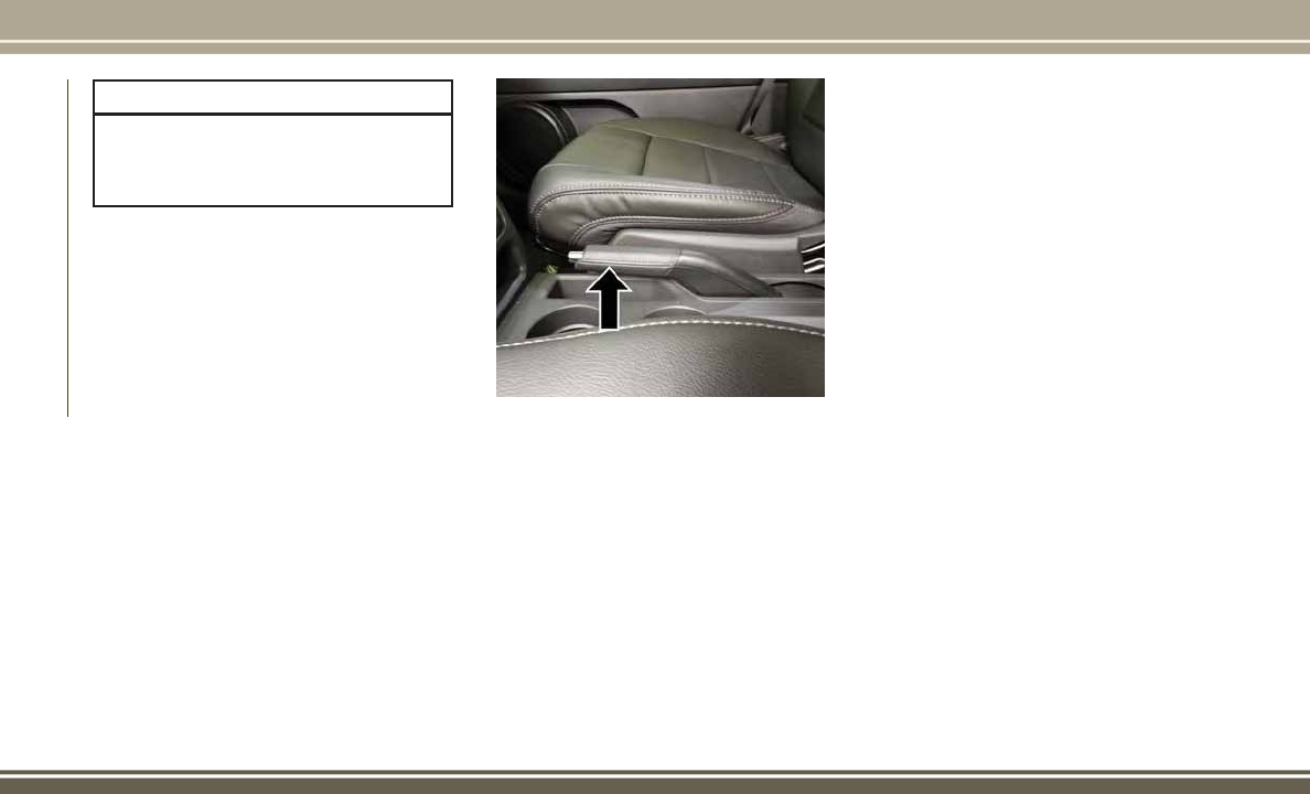
CAUTION!
Never use Non-Detergent Oil or Straight
Mineral Oil in the engine or damage may
result.
NOTE:
A new engine may consume some oil during
its first few thousand miles (kilometers) of
operation. This should be considered a nor-
mal part of the break-in and not interpreted
as a problem.
PARKING BRAKE
Before leaving the vehicle, make sure that
the parking brake is fully applied. Also, be
certain to leave an automatic transmission in
PARK, or manual transmission in REVERSE
or first gear.
The parking brake lever is located in the
center console. To apply the parking brake,
pull the lever up as firmly as possible. To
release the parking brake, pull the lever up
slightly, push the center button, then lower
the lever completely.
When the parking brake is applied with the
ignition switch in the ON position, the “Brake
Warning Light” in the instrument cluster will
illuminate.
NOTE:
• When the parking brake is applied and the
automatic transmission is placed in gear,
the “Brake Warning Light” will flash. If
vehicle speed is detected, a chime will
sound to alert the driver. Fully release the
parking brake before attempting to move
the vehicle.
• This light only shows that the parking
brake is applied. It does not show the
degree of brake application.
When parking on a hill, it is important to turn
the front wheels toward the curb on a down-
hill grade and away from the curb on an uphill
grade. For vehicles equipped with an auto-
matic transmission, apply the parking brake
before placing the gear selector in PARK,
otherwise the load on the transmission lock-
ing mechanism may make it difficult to move
the gear selector out of PARK. The parking
brake should always be applied whenever the
driver is not in the vehicle.
Parking Brake
STARTING AND OPERATING
122
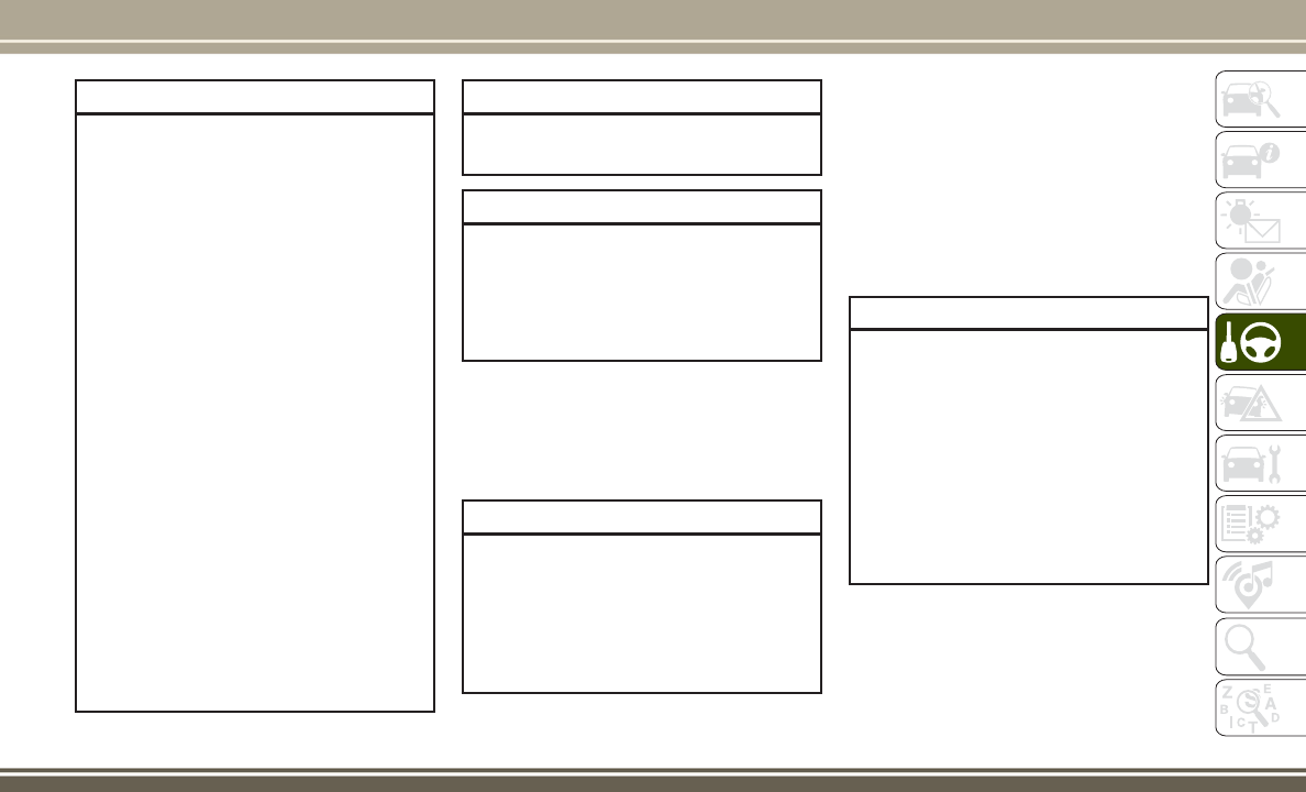
WARNING!
• When leaving the vehicle, always remove
the key fob from the ignition and lock
your vehicle.
• Never leave children alone in a vehicle,
or with access to an unlocked vehicle.
• Allowing children to be in a vehicle un-
attended is dangerous for a number of
reasons. A child or others could be seri-
ously or fatally injured. Children should
be warned not to touch the parking
brake, brake pedal or the gear selector.
• Do not leave the key fob in or near the
vehicle, or in a location accessible to
children. A child could operate power
windows, other controls, or move the
vehicle.
• Be sure the parking brake is fully disen-
gaged before driving; failure to do so can
lead to brake failure and a collision.
• Always fully apply the parking brake
when leaving your vehicle or it may roll
and cause damage or injury. Also, be
certain to leave an automatic transmis-
sion in PARK, a manual transmission in
REVERSE or first gear. Failure to do so
WARNING!
may cause the vehicle to roll and cause
damage or injury.
CAUTION!
If the Brake System Warning Light remains
on with the parking brake released, a brake
system malfunction is indicated. Have the
brake system serviced by an authorized
dealer immediately.
MANUAL TRANSMISSION —
IF EQUIPPED
Five-Speed Manual Transmission
WARNING!
You or others could be injured if you leave
the vehicle unattended without having the
parking brake fully applied. The parking
brake should always be applied when the
driver is not in the vehicle, especially on an
incline.
Fully press the clutch pedal before you shift
gears. As you release the clutch pedal, lightly
press the accelerator pedal.
Use each gear in numerical order, do not skip
a gear. Be sure the transmission is in first
gear, (not third), when starting from a stand-
ing position. Damage to the clutch can result
from starting in a gear higher than first gear.
CAUTION!
• Launching in any gear except 1st gear
will result in excessive slipping of the
clutch and potentially lugging or stalling
the engine.
• Use each gear in numerical order, do not
skip a gear. Be sure the transmission is
in first gear, (not third), when starting
from a standing position. Damage to the
clutch can result from starting in a gear
higher than first gear.
For most city driving, you will find it easier to
use only the lower gears. For steady highway
driving with light accelerations, fifth gear is
recommended.
123
Never drive with your foot resting on the
clutch pedal, and never try to hold the vehicle
on a hill with the clutch pedal partially en-
gaged. This will cause abnormal wear on the
clutch.
Never shift into REVERSE until the vehicle
has come to a complete stop.
NOTE:
During cold weather, until the transmission
lubricant is warm, you may experience
slightly higher shift efforts. This is normal
and not harmful to the transmission.
Recommended Shift Speeds
To use your manual transmission for optimal
fuel economy, it should be upshifted as listed
in the following table.
Manual Transmission Recommended Shift Speeds
Units in mph (km/h)
Engine Size Acceleration Rate 1 to 2 2 to 3 3 to 4 4 to 5
All Engines
Accel 14 (23) 23 (37) 29 (47) 45 (72)
Cruise 12 (19) 18 (29) 25 (40) 32 (52)
Downshifting
Proper downshifting will improve fuel
economy and prolong engine life.
CAUTION!
If you skip a gear while downshifting or
downshift at too high of a vehicle speed,
these conditions may cause the engine to
overspeed if too low of a gear is selected
and the clutch pedal is released. Damage
to the clutch and the transmission can
CAUTION!
result from skipping a gear while down-
shifting or downshifting at too high of a
vehicle speed even if the clutch pedal is
held pressed (i.e., not released).
To maintain a safe speed and prolong brake
life, shift down to second or first gear when
descending a steep grade.
When turning a corner or driving up a steep
grade, downshift early so that the engine will
not be overburdened.
AUTOMATIC
TRANSMISSION — IF
EQUIPPED
CAUTION!
Damage to the transmission may occur if
the following precautions are not ob-
served:
STARTING AND OPERATING
124

CAUTION!
• Shift into or out of PARK or REVERSE
only after the vehicle has come to a
complete stop.
• Do not shift between PARK, REVERSE,
NEUTRAL, or DRIVE when the engine is
above idle speed.
• Before shifting into any gear, make sure
your foot is firmly pressing the brake
pedal.
NOTE:
You must press and hold the brake pedal
while shifting out of PARK.
WARNING!
• It is dangerous to shift out of PARK or
NEUTRAL if the engine speed is higher
than idle speed. If your foot is not firmly
pressing the brake pedal, the vehicle
could accelerate quickly forward or in
reverse. You could lose control of the
vehicle and hit someone or something.
Only shift into gear when the engine is
WARNING!
idling normally and your foot is firmly
pressing the brake pedal.
• Unintended movement of a vehicle
could injure those in or near the vehicle.
As with all vehicles, you should never
exit a vehicle while the engine is run-
ning. Before exiting a vehicle always
apply the parking brake, shift the trans-
mission into PARK, turn the engine OFF,
and remove the ignition key. Once the
key is removed, the transmission is
locked in PARK, securing the vehicle
against unwanted movement.
• When leaving the vehicle, always remove
the ignition key from the vehicle and
lock the vehicle.
• Never leave children alone in a vehicle,
or with access to an unlocked vehicle.
Allowing children to be in a vehicle un-
attended is dangerous for a number of
reasons. A child or others could be seri-
ously or fatally injured. Children should
be warned not to touch the parking
brake, brake pedal or the transmission
gear selector.
WARNING!
• Do not leave the ignition key in or near
the vehicle (or in a location accessible to
children). A child could operate power
windows, other controls, or move the
vehicle.
Key Ignition Park Interlock
This vehicle is equipped with a Key Ignition
Park Interlock which requires the transmis-
sion to be in PARK before the ignition switch
can be turned to the LOCK/OFF (key removal)
position. The key can only be removed from
the ignition when the ignition is in the LOCK/
OFF position, and once removed the trans-
mission is locked in PARK.
NOTE:
If a malfunction occurs, the system will trap
the key in the ignition switch to warn you that
this safety feature is inoperable. The engine
can be started and stopped but the key can-
not be removed until you obtain service.
125

Brake/Transmission Shift Interlock
System
This vehicle is equipped with a Brake Trans-
mission Shift Interlock system (BTSI) that
holds the gear selector in PARK unless the
brakes are applied. To shift the transmission
out of PARK, the ignition switch must be
turned to the ON/RUN position (engine run-
ning or not) and the brake pedal must be
pressed.
Six-Speed Automatic Transmission — If
Equipped
The transmission gear position display (lo-
cated in the instrument cluster) indicates the
transmission gear range. You must press the
brake pedal to move the gear selector out of
PARK (refer to “Brake/Transmission Shift In-
terlock System” in this section). To drive,
move the gear selector from PARK or NEU-
TRAL to the DRIVE position.
The electronically-controlled transmission
provides a precise shift schedule. The trans-
mission electronics are self-calibrating;
therefore, the first few shifts on a new vehicle
may be somewhat abrupt. This is a normal
condition, and precision shifts will develop
within a few hundred miles (kilometers).
Only shift from DRIVE to PARK or REVERSE
when the accelerator pedal is released and
the vehicle is stopped. Be sure to keep your
foot on the brake pedal when shifting be-
tween these gears.
The transmission gear selector has only
PARK, REVERSE, NEUTRAL, and DRIVE
shift positions. Manual shifts can be made
using the AutoStick shift control (refer to
“AutoStick (Six-Speed Automatic Transmis-
sion)” in this section). Moving the gear selec-
tor to the left or right (-/+) while in the DRIVE
position will manually select the transmis-
sion gear, and will display the current gear in
the instrument cluster as 1, 2, 3, etc.
AutoStick (Six-Speed Automatic Transmis-
sion) — If Equipped
AutoStick is a driver-interactive transmission
feature providing manual shift control, giving
you more control of the vehicle. AutoStick
allows you to maximize engine braking, elimi-
nate undesirable upshifts and downshifts,
and improve overall vehicle performance.
This system can also provide you with more
control during passing, city driving, cold slip-
pery conditions, mountain driving, trailer
towing, and many other situations.
Operation
When the gear selector is in the DRIVE posi-
tion, the transmission will operate automati-
cally, shifting between the six available
gears. To engage AutoStick, simply tap the
gear selector to the right or left (+/-) while in
the DRIVE position. Tapping (-) to enter
AutoStick mode will downshift the transmis-
sion to the next lower gear, while using (+) to
enter AutoStick mode will retain the current
gear. When AutoStick is active, the current
transmission gear is displayed in the instru-
ment cluster.
In AutoStick mode, the transmission will
shift up or down when the driver moves the
gear selector to the right (+) or left (-), unless
an engine lugging or overspeed condition
would result. It will remain in the selected
STARTING AND OPERATING
126

gear until another upshift or downshift is
chosen, except as described below:
• The transmission will automatically up-
shift when necessary to prevent engine
over-speed.
• The transmission will automatically down-
shift as the vehicle slows (to prevent en-
gine lugging) and will display the current
gear.
• The transmission will automatically down-
shift to first gear when coming to a stop.
After a stop, the driver should manually
upshift (+) the transmission as the vehicle
is accelerated.
• You can start out, from a stop, in first or
second gear. Tapping (+) (at a stop) will
allow starting in second gear. Starting out
in second gear can be helpful in snowy or
icy conditions.
• If a requested downshift would cause the
engine to overspeed, that shift will not
occur.
• Avoid using speed control when AutoStick
is engaged.
• Transmission shifting will be more notice-
able when AutoStick is engaged.
• The system may revert to automatic shift
mode if a fault or overheat condition is
detected.
To disengage AutoStick mode, hold the gear
selector to the right (+) until “D” is once
again displayed in the instrument cluster.
You can shift in or out of the AutoStick mode
at any time without taking your foot off the
accelerator pedal.
WARNING!
Do not downshift for additional engine
braking on a slippery surface. The drive
wheels could lose their grip and the ve-
hicle could skid, causing a collision or
personal injury.
Continuously Variable Automatic
Transmission (CVT) — If Equipped
The transmission gear position display (lo-
cated in the instrument cluster) indicates the
transmission gear range. You must press the
brake pedal to move the gear selector out of
PARK (refer to “Brake/Transmission Shift In-
terlock System” in this section). To drive,
move the gear selector from PARK or NEU-
TRAL to the DRIVE position.
NOTE:
The Continuously Variable Automatic Trans-
mission (CVT) changes ratios in a continuous
manner. This may sometimes "feel" as if it is
slipping, but this is normal and does not
harm anything.
Only shift from DRIVE to PARK or REVERSE
when the accelerator pedal is released and
the vehicle is stopped. Be sure to keep your
foot on the brake pedal when shifting be-
tween these gears.
The transmission gear selector has only
PARK, REVERSE, NEUTRAL, and DRIVE
shift positions. Manual shifts can be made
using the AutoStick shift control (refer to
"AutoStick (CVT)" in this section). Moving the
gear selector to the left or right (-/+) while in
the DRIVE position will manually select from
a set of predefined transmission gear ratios,
and will display the current gear in the instru-
ment cluster as 1, 2, 3, etc.
127

AutoStick (CVT) — If Equipped
AutoStick is a driver-interactive transmission
feature providing six manually selectable
gear ratios, giving you more control of the
vehicle. AutoStick allows you to maximize
engine braking, eliminate undesirable up-
shifts and downshifts, and improve overall
vehicle performance. This system can also
provide you with more control during passing,
city driving, cold slippery conditions, moun-
tain driving, trailer towing, and many other
situations.
Operation
NOTE:
AutoStick is not available until the CVT
warms up in cold weather.
When the gear selector is in the DRIVE posi-
tion, AutoStick is activated by moving the
gear selector side-to-side. Moving the gear
selector to the right (+) will activate
AutoStick and shift up to the next higher
manual ratio, unless you are already operat-
ing in or near Overdrive, in which case sixth
gear ratio will be selected. In like manner,
moving the gear selector to the left (-) will
activate AutoStick and shift to the next lower
manual ratio. The manually-selected gear
will be displayed in the instrument cluster.
In AutoStick mode, the transmission will
shift up or down when (+/-) is manually se-
lected by the driver, unless an engine lugging
or overspeed condition would result. It will
remain in the selected gear until another
upshift or downshift is chosen, except as
described below:
• The transmission will automatically up-
shift when necessary to prevent engine
over-speed.
• The transmission will automatically down-
shift as the vehicle slows (to prevent en-
gine lugging) and will display the current
gear.
• The transmission will automatically down-
shift to first gear when coming to a stop.
After a stop, the driver should manually
upshift (+) the transmission as the vehicle
is accelerated.
• If a requested downshift would cause the
engine to overspeed, that shift will not
occur.
• Transmission shifting will be more notice-
able when AutoStick is engaged.
• Heavy Anti-Lock Brake System (ABS) ap-
plication will disengage AutoStick mode.
• The system may revert to automatic shift
mode if a fault or overheat condition is
detected.
To disengage AutoStick mode, hold the gear
selector to the right (+) until “D” is once
again displayed in the instrument cluster.
You can shift in or out of the AutoStick mode
at any time without taking your foot off the
accelerator pedal.
WARNING!
Do not downshift for additional engine
braking on a slippery surface. The drive
wheels could lose their grip and the ve-
hicle could skid, causing a collision or
personal injury.
STARTING AND OPERATING
128

FOUR-WHEEL DRIVE
OPERATION — IF EQUIPPED
This feature provides full time, on-demand,
four–wheel drive (4WD).
Where one or more wheels have wheel spin or
if additional traction is needed in sand, deep
snow, or loose traction surfaces, activate the
“4WD LOCK” switch by pulling up once and
releasing. This locks the center coupling al-
lowing more torque to be sent to the rear
wheels. The “4WD Indicator Light” will come
on in the cluster. This can be done on the fly,
at any vehicle speed. To deactivate, simply
pull on the switch one more time. The “4WD
Indicator Light” will then go out.
NOTE:
Refer to “Electronic Brake Control System/
Electronic Stability Control (ESC)” in
“Safety” for further information.
SPEED CONTROL
When engaged, the Speed Control takes over
accelerator operations at speeds greater than
25 mph (40 km/h).
The Speed Control buttons are located on the
right side of the steering wheel.
NOTE:
In order to ensure proper operation, the
Speed Control System has been designed to
Four-Wheel Drive Switch
Speed Control Buttons
1 — Push Cancel
2 — Push On/Off
3 — Push Resume/Accel
4 — Push Set/Decel
129

shut down if multiple Speed Control func-
tions are operated at the same time. If this
occurs, the Speed Control System can be
reactivated by pushing the Speed Control
on/off button and resetting the desired ve-
hicle set speed.
To Activate
Push the on/off button. The cruise control
indicator light in the instrument cluster dis-
play will illuminate. To turn the system off,
push the on/off button a second time. The
cruise control indicator light will turn off. The
system should be turned off when not in use.
WARNING!
Leaving the Speed Control system on when
not in use is dangerous. You could acci-
dentally set the system or cause it to go
faster than you want. You could lose con-
trol and have an accident. Always leave the
system off when you are not using it.
To Set A Desired Speed
Turn the Speed Control on. When the vehicle
has reached the desired speed, push the SET
(-) button and release. Release the accelera-
tor and the vehicle will operate at the se-
lected speed.
NOTE:
The vehicle should be traveling at a steady
speed and on level ground before pushing the
SET (-) button.
To Deactivate
A soft tap on the brake pedal, pushing the
CANC button or normal brake pressure while
slowing the vehicle will deactivate the Speed
Control without erasing the set speed from
memory.
Pushing the on/off button or turning the igni-
tion to the OFF position erases the set speed
from memory.
To Resume Speed
To resume a previously set speed, push the
RES (+) button and release. Resume can be
used at any speed above 20 mph (32 km/h).
To Vary The Speed Setting
To Increase Speed
When the Speed Control is set, you can in-
crease speed by pushing the RES (+) button.
The driver’s preferred units can be selected
through the instrument panel settings if
equipped. Refer to “Getting To Know Your
Instrument Panel” in the Owner’s Manual on
www.jeep.com/en/owners/manuals/ for more
information. The speed increment shown is
dependent on the chosen speed unit of U.S.
(mph) or Metric (km/h):
U.S. Speed (mph)
• Pushing the RES (+) button once will
result in a 1 mph increase in set speed.
Each subsequent tap of the button results
in an increase of 1 mph.
• If the button is continually pushed, the set
speed will continue to increase until the
button is released, then the new set speed
will be established.
STARTING AND OPERATING
130

Metric Speed (km/h)
• Pushing the RES (+) button once will re-
sult in a 1 km/h increase in set speed.
Each subsequent tap of the button results
in an increase of 1 km/h.
• If the button is continually pushed, the set
speed will continue to increase until the
button is released, then the new set speed
will be established.
To Decrease Speed
When the Speed Control is set, you can de-
crease speed by pushing the SET (-) button.
The driver’s preferred units can be selected
through the instrument panel settings if
equipped. Refer to “Getting To Know Your
Instrument Panel” in the Owner’s Manual on
www.jeep.com/en/owners/manuals/ for more
information. The speed increment shown is
dependent on the chosen speed unit of U.S.
(mph) or Metric (km/h):
U.S. Speed (mph)
• Pushing the SET (-) button once will result
in a 1 mph decrease in set speed. Each
subsequent tap of the button results in a
decrease of 1 mph.
• If the button is continually pushed, the set
speed will continue to decrease until the
button is released, then the new set speed
will be established.
Metric Speed (km/h)
• Pushing the SET (-) button once will result
in a 1 km/h decrease in set speed. Each
subsequent tap of the button results in a
decrease of 1 km/h.
• If the button is continually pushed, the set
speed will continue to decrease until the
button is released, then the new set speed
will be established.
To Accelerate For Passing
Press the accelerator as you would normally.
When the pedal is released, the vehicle will
return to the set speed.
Using Speed Control On Hills
The transmission may downshift on hills to
maintain the vehicle set speed.
NOTE:
The Speed Control system maintains speed
up and down hills. A slight speed change on
moderate hills is normal.
On steep hills, a greater speed loss or gain
may occur so it may be preferable to drive
without Speed Control.
WARNING!
Speed Control can be dangerous where the
system cannot maintain a constant speed.
Your vehicle could go too fast for the con-
ditions, and you could lose control and
have an accident. Do not use Speed Con-
trol in heavy traffic or on roads that are
winding, icy, snow-covered or slippery.
PARKVIEW REAR BACK UP
CAMERA — IF EQUIPPED
Your vehicle may be equipped with the
ParkView Rear Back Up Camera that allows
you to see an on-screen image of the rear
surroundings of your vehicle whenever the
gear selector is put into REVERSE. The image
will be displayed on the touchscreen along
with a caution note to “check entire sur-
roundings” across the top of the screen. After
131
five seconds, this note will disappear. The
ParkView camera is located on the rear of the
vehicle above the rear license plate.
When the vehicle is shifted out of REVERSE,
the rear camera mode is exited and the last
selected touchscreen appears again.
If your vehicle is equipped with the Camera
Delay feature and it is turned on, the rear
camera image will be displayed for up to
10 seconds when the vehicle is shifted out of
REVERSE unless the forward vehicle speed
exceeds 8 mph (13 km/h), the transmission
is shifted into PARK or the vehicle’s ignition
is cycled to the OFF position.
Static grid lines will illustrate the width of the
vehicle. The static grid lines will show sepa-
rate zones that will help indicate the distance
to the rear of the vehicle. Different colored
zones indicate the distance to the rear of the
vehicle. The following table shows the ap-
proximate distances for each zone:
Zone Distance to the rear of the vehicle
Red 0-1ft(0-30cm)
Yellow 1 ft - 3 ft (30 cm - 1 m)
Green 3 ft or greater (1 m or greater)
WARNING!
Drivers must be careful when backing up
even when using the ParkView Rear Back
Up Camera. Always check carefully behind
your vehicle, and be sure to check for
pedestrians, animals, other vehicles, ob-
structions, or blind spots before backing
up. You are responsible for the safety of
your surroundings and must continue to
pay attention while backing up. Failure to
do so can result in serious injury or death.
CAUTION!
• To avoid vehicle damage, ParkView
should only be used as a parking aid.
The ParkView camera is unable to view
every obstacle or object in your drive
path.
• To avoid vehicle damage, the vehicle
must be driven slowly when using
ParkView to be able to stop in time when
an obstacle is seen. It is recommended
CAUTION!
that the driver look frequently over his/
her shoulder when using ParkView.
NOTE:
If snow, ice, mud or any foreign substance
builds up on the camera lens, clean the lens,
rinse with water and dry with a soft cloth. Do
not cover the lens.
STARTING AND OPERATING
132

ADDING FUEL
Fuel Filler Cap (Gas Cap)
The gas cap is behind the fuel filler door, on
the left side of the vehicle. If the gas cap is
lost or damaged, be sure the replacement cap
is for use with this vehicle.
After removing the gas cap, place the gas cap
tether cable over a hook on the inside of the
fuel door. This keeps the gas cap suspended
away from and protects the vehicle's surface.
CAUTION!
• Damage to the fuel system or emission
control system could result from using
an improper fuel tank filler cap. A poorly
fitting cap could let impurities into the
fuel system.
• A poorly fitting fuel filler cap may cause
the “Malfunction Indicator Light (MIL)”
to turn on.
• To avoid fuel spillage and overfilling, do
not “top off” the fuel tank after filling.
WARNING!
• Never have any smoking materials lit in
or near the vehicle when the gas cap is
removed or the tank is being filled.
• Never add fuel when the engine is run-
ning. This is in violation of most state
and federal fire regulations and may
cause the MIL to turn on.
• A fire may result if gasoline is pumped
into a portable container that is inside of
a vehicle. You could be burned. Always
WARNING!
place gas containers on the ground while
filling.
NOTE:
• When the fuel nozzle “clicks” or shuts off,
the fuel tank is full.
• Tighten the gas cap about ¼ turn until you
hear one click. This is an indication that
cap is properly tightened.
• If the gas cap is not tightened properly, the
MIL will come on. Be sure the gas cap is
tightened every time the vehicle is
refueled.
Loose Fuel Filler Cap Message
If the vehicle diagnostic system determines
that the fuel filler cap is loose or improperly
installed, a “gASCAP” message will be dis-
played in the Odometer/Trip Odometer in the
instrument cluster. Refer to “Warning And
Indicator Lights” in “Getting To Know Your
Instrument Panel” for further information.
Tighten the fuel filler cap properly and push
the odometer/trip odometer RESET button to
turn the message off. If the problem contin-
Fuel Filler Cap
133

ues, the message will appear the next time
the vehicle is started. Refer to “Onboard
Diagnostic System” in “Getting To Know Your
Instrument Panel” for further information.
VEHICLE LOADING
Certification Label
As required by National Highway Traffic
Safety Administration regulations, your ve-
hicle has a certification label affixed to the
driver's side door or pillar.
This label contains the month and year of
manufacture, Gross Vehicle Weight Rating
(GVWR), Gross Axle Weight Rating (GAWR)
front and rear, and Vehicle Identification
Number (VIN). A Month-Day-Hour (MDH)
number is included on this label and indi-
cates the Month, Day and Hour of manufac-
ture. The bar code that appears on the bot-
tom of the label is your VIN.
Gross Vehicle Weight Rating (GVWR)
The GVWR is the total permissible weight of
your vehicle including driver, passengers, ve-
hicle, options and cargo. The label also
specifies maximum capacities of front and
rear axle systems (GAWR). Total load must be
limited so GVWR and front and rear GAWR
are not exceeded.
Payload
The payload of a vehicle is defined as the
allowable load weight a truck can carry, in-
cluding the weight of the driver, all passen-
gers, options and cargo.
Gross Axle Weight Rating (GAWR)
The GAWR is the maximum permissible load
on the front and rear axles. The load must be
distributed in the cargo area so that the
GAWR of each axle is not exceeded.
Each axle GAWR is determined by the com-
ponents in the system with the lowest load
carrying capacity (axle, springs, tires or
wheels). Heavier axles or suspension compo-
nents sometimes specified by purchasers for
increased durability does not necessarily in-
crease the vehicle's GVWR.
Tire Size
The tire size on the Vehicle Certification La-
bel represents the actual tire size on your
vehicle. Replacement tires must be equal to
the load capacity of this tire size.
Rim Size
This is the rim size that is appropriate for the
tire size listed.
Inflation Pressure
This is the cold tire inflation pressure for your
vehicle for all loading conditions up to full
GAWR.
STARTING AND OPERATING
134

Curb Weight
The curb weight of a vehicle is defined as the
total weight of the vehicle with all fluids,
including vehicle fuel, at full capacity condi-
tions, and with no occupants or cargo loaded
into the vehicle. The front and rear curb
weight values are determined by weighing
your vehicle on a commercial scale before
any occupants or cargo are added.
Loading
The actual total weight and the weight of the
front and rear of your vehicle at the ground
can best be determined by weighing it when it
is loaded and ready for operation.
The entire vehicle should first be weighed on
a commercial scale to insure that the GVWR
has not been exceeded. The weight on the
front and rear of the vehicle should then be
determined separately to be sure that the
load is properly distributed over the front and
rear axle. Weighing the vehicle may show that
the GAWR of either the front or rear axles has
been exceeded but the total load is within the
specified GVWR. If so, weight must be
shifted from front to rear or rear to front as
appropriate until the specified weight limita-
tions are met. Store the heavier items down
low and be sure that the weight is distributed
equally. Stow all loose items securely before
driving.
Improper weight distributions can have an
adverse effect on the way your vehicle steers
and handles and the way the brakes operate.
CAUTION!
Do not load your vehicle any heavier than
the GVWR or the maximum front and rear
GAWR. If you do, parts on your vehicle can
break, or it can change the way your ve-
hicle handles. This could cause you to lose
control. Also overloading can shorten the
life of your vehicle.
135

TRAILER TOWING
Trailer Towing Weights (Maximum Trailer Weight Ratings)
Engine/Transmission Frontal Area Maximum GTW (Gross Trailer Wt.) Maximum Tongue Wt. (See Note)
2.0L Auto/Man 22 sq ft (2.04 sq m) 1,000 lbs (453 kg) 150 lbs (68 kg)
2.4L Auto/Man 22 sq ft (2.04 sq m) 1,000 lbs (453 kg) 150 lbs (68 kg)
2.4L Auto/Man with Trailer Tow
Prep Package (AHC)
32 sq ft (3.0 sq m) 2,000 lbs (907 kg) 300 lbs (136 kg)
2.4L Auto With Freedom Drive II
Off Road Package (AWL)
32 sq ft (3.0 sq m) 2,000 lbs (907 kg) 300 lbs (136 kg)
Refer to local laws for maximum trailer towing speeds.
NOTE:
The trailer tongue weight must be considered
as part of the combined weight of occupants
and cargo, and should never exceed the
weight referenced on the Tire and Loading
Information placard. Refer to “Tire Safety
Information” in “Servicing And Mainte-
nance” for further information.
STARTING AND OPERATING
136

RECREATIONAL TOWING (BEHIND MOTORHOME, ETC.)
Towing This Vehicle Behind Another Vehicle
Towing Condition Wheels OFF the Ground Manual Transmission Automatic Transmission
Flat Tow None
•
Transmission in NEUTRAL
• Key in ACC Position
NOT ALLOWED
Dolly Tow
Front FWD Models ONLY FWD Models ONLY
Rear NOT ALLOWED NOT ALLOWED
On Trailer All OK OK
NOTE:
• When recreational towing your vehicle, al-
ways follow applicable state and provincial
laws. Contact state and provincial High-
way Safety offices for additional details.
• Vehicles equipped with manual transmis-
sions may be recreational towed (flat
towed) at any legal highway speed, for any
distance, if the manual transmission is in
NEUTRAL and the ignition key is in the
ACC position.
CAUTION!
• DO NOT flat tow any vehicle equipped
with an automatic transmission. Dam-
age to the drivetrain will result. If these
vehicles require towing, make sure all
drive wheels are OFF the ground.
• DO NOT dolly tow any 4WD vehicle.
Internal damage to the transmission or
transfer case will occur if a dolly is used
when recreational towing.
137

138

IN CASE OF EMERGENCY
HAZARD WARNING FLASHERS
. .140
BULB REPLACEMENT ........140
Replacement Bulbs ............140
Replacing Exterior Bulbs..........141
Headlamps ..................141
Fog Lamps ..................141
Rear Tail, Turn Signal And Backup
Lamps ....................141
License Lamps ...............141
Center High-Mounted Stoplamp .....141
FUSES....................142
Integrated Power Module (IPM)......142
JACKING AND TIRE CHANGING
. .144
Jack Location ................145
Spare Tire Stowage .............145
Preparations For Jacking .........146
Jacking Instructions ............146
Road Tire Installation ............151
TIRESERVICEKIT ...........152
Tire Service Kit Storage ..........152
Tire Service Kit Components And
Operation ...................152
Tire Service Kit Usage Precautions. . . .153
Sealing A Tire With Tire Service Kit . . .154
JUMP-STARTING PROCEDURES
. .157
Preparations For Jump-Start .......158
Jump-Starting Procedure .........159
IF YOUR ENGINE OVERHEATS . .160
GEAR SELECTOR OVERRIDE. . . .161
FREEING A STUCK VEHICLE . . . .161
TOWING A DISABLED VEHICLE
. .163
ENHANCED ACCIDENT RESPONSE
SYSTEM(EARS).............164
EVENT DATA RECORDER (EDR)
. .164
IN CASE OF EMERGENCY
139

HAZARD WARNING
FLASHERS
The Hazard Warning flasher switch is located
on the instrument panel below the climate
controls.
Push the switch to turn on
the Hazard Warning
flasher. When the switch
is activated, all direc-
tional turn signals will
flash on and off to warn oncoming traffic of
an emergency. Push the switch a second time
to turn off the Hazard Warning flashers.
This is an emergency warning system and it
should not be used when the vehicle is in
motion. Use it when your vehicle is disabled
and it is creating a safety hazard for other
motorists.
When you must leave the vehicle to seek
assistance, the Hazard Warning flashers will
continue to operate even though the ignition
is placed in the OFF position.
NOTE:
With extended use, the Hazard Warning
flashers may wear down your battery.
BULB REPLACEMENT
Replacement Bulbs
All the inside bulbs are brass or glass wedge
base. Aluminum base bulbs are not approved
and should not be used for replacement
Interior Bulbs
Bulb Number
Front Header Lamp T578
Center Dome Lamp T578
Rear Cargo Lamp/Flashlight 8–A35LF
Exterior Bulbs
Bulb Number
Low Beam/High Beam Headlamp H13
Front Park/Turn Signal/Side Marker Lamp 3757KA
Front Fog Lamp PSX24W
Center High Mounted Stop Lamp (CHMSL) LED Assembly (Serviced At Authorized Dealer)
IN CASE OF EMERGENCY
140

Bulb Number
Rear Tail/Turn/Stop Lamp 3157
Backup Lamp W16W (921)
License Lamp W5W
Replacing Exterior Bulbs
Headlamps
1. Raise the hood and locate the connector
behind the headlamp.
2. Reach into engine compartment and pull
red lock out at connector.
3. Remove the green connector from the
back of the bulb by pulling straight back.
4. Twist the bulb to the left.
5. Pull bulb outward from assembly.
NOTE:
These are halogen bulbs. Take care not to
touch the bulb with your fingers. Body oils
from your fingers could cause excessive heat
buildup which reduces bulb life.
Fog Lamps
1. Access lamp through the lower fascia
cutout.
2. Remove electrical connector from bulb.
3. Remove bulb from housing.
CAUTION!
Do not touch the new bulb with your fin-
gers. Oil contamination will severely
shorten bulb life. If the bulb comes in
contact with any oily surface, clean the
bulb with rubbing alcohol.
Rear Tail, Turn Signal And Backup Lamps
1. Raise the liftgate.
2. Remove the two push-pins from the tail-
lamp housing.
3. Grasp the taillamp and pull firmly to dis-
engage the light from the aperture panel.
4. Twist and remove socket from the light.
5. Remove bulb from socket and replace.
License Lamps
1. Use a screw driver to gently pry against
the side of the snap tab to remove the
lamp from the liftgate.
2. Rotate the socket 1/4 turn
counterclockwise.
3. Pull the bulb from the socket.
Center High-Mounted Stoplamp
This light is an LED assembly. See your au-
thorized dealer for replacement.
141

FUSES
WARNING!
• When replacing a blown fuse, always use
an appropriate replacement fuse with
the same amp rating as the original fuse.
Never replace a fuse with another fuse of
higher amp rating. Never replace a
blown fuse with metal wires or any other
material. Failure to use proper fuses may
result in serious personal injury, fire
and/or property damage.
• Before replacing a fuse, make sure that
the ignition is off and that all the other
services are switched off and/or disen-
gaged.
WARNING!
• If the replaced fuse blows again, contact
an authorized dealer.
• If a general protection fuse for safety
systems (air bag system, braking sys-
tem), power unit systems (engine sys-
tem, transmission system) or steering
system blows, contact an authorized
dealer.
Integrated Power Module (IPM)
The Integrated Power Module is located in
the engine compartment near the air cleaner
assembly. This center contains cartridge
fuses and mini-fuses. A label that identifies
each component may be printed on the in-
side of the cover. Refer to “Engine Compart-
ment” in “Servicing And Maintenance” for
further information.
Cavity Cartridge Fuse Mini-Fuse Description
1 20 Amp Blue – Trailer Tow – If Equipped
2 – 15 Amp Lt Blue AWD/4WD Control Module – If Equipped
3 – 10 Amp Red Rear Center Brake Light Switch
4 – 10 Amp Red Ignition Switch/Clock Spring
5 – 15 Amp Lt Blue Battery Feed For Power Tech
Integrated Power Module
IN CASE OF EMERGENCY
142

Cavity Cartridge Fuse Mini-Fuse Description
6 – 10 Amp Red Power Mirror/Steering Control Satellite Radio/Hands-
Free Phone
7 – 30 Amp Green Ignition Off Draw
8 – 30 Amp Green Ignition Off Draw
9 40 Amp Green – Power Seats
10 – 20 Amp Yellow Power Locks/Interior Lighting
11 – 15 Amp Lt Blue Power Outlet
12 – 20 Amp Yellow 115V AC Inverter – If Equipped
13 – 20 Amp Yellow Cigar Lighter
14 – 10 Amp Red Instrument Cluster
15 40 Amp Green – Radiator Fan
16 – 15 Amp Lt Blue Dome Lamp/Sunroof/Rear Wiper Motor
17 – 10 Amp Red Wireless Control Module
18 40 Amp Green – Auto Shutdown Relay
19 – 20 Amp Yellow Radio Amplifiers
20 – 15 Amp Lt Blue Radio
21 – 10 Amp Red Intrusion Module/Siren – If Equipped
22 – 10 Amp Red Heating, AC/Compass
23 – 15 Amp Lt Blue Auto Shutdown Relay
24 – 15 Amp Lt Blue Power Sunroof – If Equipped
25 – 10 Amp Red Heated Mirror – If Equipped
26 – 15 Amp Lt Blue Auto Shutdown Relay
27 – 10 Amp Red Airbag Control Module
143

Cavity Cartridge Fuse Mini-Fuse Description
28 – 10 Amp Red Airbag Control Module/Occupant Classification Mod-
ule
29 – – Hot Vehicle (No Fuse Required)
30 – 20 Amp Yellow Heated Seat – If Equipped
31 – 10 Amp Red Headlamp Washer – If Equipped
32 30 Amp Pink – Auto Shutdown Relay
33 – 10 Amp Red J1962 Conn/Powertrain Control Module
34 30 Amp Pink – Antilock BrakeValve
35 40 Amp Green – Antilock Brake Pump
36 30 Amp Pink – Headlamp/Washer Control/Smart Glass – If Equipped
37 – 25 Amp Clear Diesel Heater and H2/MOD power top
CAUTION!
• When installing the IPM cover, it is im-
portant to ensure the cover is properly
positioned and fully latched. Failure to
do so may allow water to get into the
IPM, and possibly result in an electrical
system failure.
• When replacing a blown fuse, it is impor-
tant to use only a fuse having the correct
amperage rating. The use of a fuse with
a rating other than indicated may result
CAUTION!
in a dangerous electrical system over-
load. If a properly rated fuse continues
to blow, it indicates a problem in the
circuit that must be corrected.
JACKING AND TIRE
CHANGING
WARNING!
• Do not attempt to change a tire on the
side of the vehicle close to moving traf-
fic. Pull far enough off the road to avoid
the danger of being hit when operating
the jack or changing the wheel.
• Being under a jacked-up vehicle is dan-
gerous. The vehicle could slip off the
IN CASE OF EMERGENCY
144

WARNING!
jack and fall on you. You could be
crushed. Never put any part of your body
under a vehicle that is on a jack. If you
need to get under a raised vehicle, take
it to a service center where it can be
raised on a lift.
• Never start or run the engine while the
vehicle is on a jack.
• The jack is designed to be used as a tool
for changing tires only. The jack should
not be used to lift the vehicle for service
purposes. The vehicle should be jacked
on a firm level surface only. Avoid ice or
slippery areas.
Jack Location
The jack and jack-handle are stowed under
the load floor in the cargo area.
Spare Tire Stowage
The compact spare tire is stowed under the
rear load floor in the cargo area.
Spare Tire Removal
Lift up the load floor cover and remove the
hold down.
Spare/Jack/Tools
1 — Spare Tire
2 — Jack And Tools
Spare Tire Location
145

Preparations For Jacking
1. Park the vehicle on a firm level surface,
avoiding ice or slippery areas.
WARNING!
Do not attempt to change a tire on the side
of the vehicle close to moving traffic, pull
far enough off the road to avoid the danger
of being hit when operating the jack or
changing the wheel.
2. Turn on the Hazard Warning flasher.
3. Set the parking brake.
4. Place the gear selector in PARK (auto-
matic transmission) or REVERSE (manual
transmission).
5. Turn OFF the ignition.
6. Block both the front and rear of the wheel
diagonally opposite of the jacking posi-
tion. For example, if changing the right
front tire, block the left rear wheel.
NOTE:
Passengers should not remain in the vehicle
while the vehicle is being jacked.
Jacking Instructions
WARNING!
Carefully follow these tire changing warn-
ings to help prevent personal injury or
damage to your vehicle:
• Always park on a firm, level surface as
far from the edge of the roadway as
possible before raising the vehicle.
• Turn on the Hazard Warning flasher.
• Block the wheel diagonally opposite the
wheel to be raised.
• Set the parking brake firmly and set an
automatic transmission in PARK; a
manual transmission in REVERSE.
• Never start or run the engine with the
vehicle on a jack.
• Do not let anyone sit in the vehicle when
it is on a jack.
• Do not get under the vehicle when it is
on a jack. If you need to get under a
raised vehicle, take it to a service center
where it can be raised on a lift.
• Only use the jack in the positions indi-
cated and for lifting this vehicle during a
tire change.
Wheel Blocked
IN CASE OF EMERGENCY
146

WARNING!
• If working on or near a roadway, be
extremely careful of motor traffic.
• To assure that spare tires, flat or in-
flated, are securely stowed, spares must
be stowed with the valve stem facing the
ground.
NOTE:
Refer to “Tires” in “Servicing And Mainte-
nance” in the Owner’s Manual at
www.jeep.com/en/owners/manuals/ for fur-
ther information about the spare tire, it's use,
and operation.
1. Remove the scissors jack and lug wrench
from the spare wheel as an assembly. Turn
the jack screw to the left to loosen the lug
wrench and remove the wrench from the
jack assembly.
NOTE:
The jack handle attaches to the side of the
jack with two attachment points. When
the jack is partially expanded, the tension
between the two attachment points holds
the jack handle in place.
2. Loosen, but do not remove, the wheel nuts
by turning them to the left one turn while
the wheel is still on the ground.
NOTE:
There are front and rear jacking locations
on each side of the body. The front loca-
tions are outlined by two triangular cut-
outs on one of the flanges in the sill flange
assembly. The rear location is the same
but with two rectangular cutouts. For ve-
hicles equipped with plastic trim, the
plastic has been cut away to expose the
jacking locations in the body.
Warning Label
147

CAUTION!
Do not attempt to raise the vehicle by
jacking on locations other than those indi-
cated in the Jacking Instructions for this
vehicle.
Jacking Locations
IN CASE OF EMERGENCY
148

Do not raise the vehicle until you are sure
the jack is securely engaged.
3. Turn the jack screw to the left until the
jack can be placed under the jacking
location. Once the jack is positioned, turn
the jack screw to the right until the jack
head is properly engaged with the lift area
closest to the wheel to be changed.
WARNING!
Raising the vehicle higher than necessary
can make the vehicle less stable. It could
slip off the jack and hurt someone near it.
Raise the vehicle only enough to remove
the tire.
4. Using the swivel wrench raise the vehicle
by turning the jack screw to the right.
Raise the vehicle only until the tire just
clears the surface and enough clearance
is obtained to install the spare tire. Mini-
mum tire lift provides maximum stability.
Front Jack Engaged Rear Jack Engaged
149

5. Remove the wheel nuts and pull the wheel
and wheel covers, where applicable, off
the hub. Install the spare wheel and wheel
nuts with the cone shaped end of the nuts
toward the wheel. Lightly tighten the nuts.
WARNING!
To avoid the risk of forcing the vehicle off
the jack, do not tighten the wheel nuts
fully until the vehicle has been lowered.
Failure to follow this warning may result in
serious injury.
WARNING!
To avoid possible personal injury, handle
the wheel covers with care to avoid contact
with any sharp edges.
CAUTION!
Be sure to mount the spare tire with the
valve stem facing outward. The vehicle
could be damaged if the spare tire is
mounted incorrectly.
NOTE:
The wheel cover is held on the wheel by
the wheel nuts. When reinstalling the
original wheel, properly align the wheel
cover to the valve stem, place the wheel
cover onto the wheel, then install the
wheel nuts.
6. Lower the vehicle by turning the jack
screw to the left.
7. Finish tightening the lug nuts. Push down
on the wrench while at the end of the
handle for increased leverage. Tighten the
lug nuts in a star pattern until each nut
has been tightened twice. Refer to
“Torque Specifications” in “Technical
Specifications” for the correct lug nut
torque. If you doubt that you have tight-
ened the nuts correctly, have them
checked with a torque wrench by your
authorized dealer or service station.
Installing Spare
IN CASE OF EMERGENCY
150

8. Remove the wheel blocks and lower the
jack until it is free. Release the parking
brake. Reassemble the lug wrench to the
jack assembly and stow it in the spare tire
area. Secure the assembly using the
means provided.
WARNING!
A loose tire or jack thrown forward in a
collision or hard stop could endanger the
occupants of the vehicle. Always stow the
jack parts and the spare tire in the places
provided.
9. Place the deflated (flat) tire in the cargo
area, have the tire repaired or replaced as
soon as possible.
WARNING!
A loose tire thrown forward in a collision or
hard stop could injure the occupants in the
vehicle. Have the deflated (flat) tire re-
paired or replaced immediately.
10. Check the spare tire pressure as soon as
possible. Correct the tire pressure as
required.
Road Tire Installation
Vehicles Equipped With Wheel Covers
1. Mount the road tire on the axle.
2. Align the valve notch in the wheel cover
with the valve stem on the wheel. Install
the cover by hand. Do not use a hammer or
excessive force to install the cover.
3. Install the five wheel lug nuts with the
cone shaped end of the nut toward the
wheel. Lightly tighten the lug nuts.
WARNING!
To avoid the risk of forcing the vehicle off
the jack, do not tighten the lug nuts fully
until the vehicle has been lowered. Failure
to follow this warning may result in serious
injury.
4. Lower the vehicle to the ground by turning
the jack handle counterclockwise.
5. Finish tightening the lug nuts. Push down
on the wrench while at the end of the
handle for increased leverage. Refer to
“Torque Specifications” in “Technical
Specifications” for correct lug nut torque.
6. After 25 miles (40 km) check the lug nut
torque with a torque wrench to ensure that
all lug nuts are properly seated against the
wheel.
Wheel Cover Installation
1 — Valve Stem
2 — Valve Notch
3 — Wheel Lug Nut
4 — Wheel Cover
5 — Mounting Stud
151

Vehicles Without Wheel Covers
1. Mount the road tire on the axle.
2. Install the remaining lug nuts with the
cone shaped end of the nut toward the
wheel. Lightly tighten the lug nuts.
WARNING!
To avoid the risk of forcing the vehicle off
the jack, do not fully tighten the lug nuts
until the vehicle has been lowered. Failure
to follow this warning may result in serious
injury.
3. Lower the vehicle to the ground by turning
the jack handle counterclockwise.
4. Finish tightening the lug nuts. Push down
on the wrench while at the end of the
handle for increased leverage. Refer to
“Torque Specifications” in “Technical
Specifications” for correct lug nut torque.
5. After 25 miles (40 km) check the lug nut
torque with a torque wrench to ensure that
all lug nuts are properly seated against the
wheel.
TIRE SERVICE KIT
Small punctures up to 1/4 inch (6 mm) in the
tire tread can be sealed with Tire Service Kit.
Foreign objects (e.g., screws or nails) should
not be removed from the tire. Tire Service Kit
can be used in outside temperatures down to
approximately -4°F (-20°C).
This kit will provide a temporary tire seal,
allowing you to drive your vehicle up to 100
miles (160 km) with a maximum speed of
55 mph (90 km/h).
Tire Service Kit Storage
The Tire Service Kit is located under the load
floor in the cargo area.
Tire Service Kit Components And
Operation
Tire Service Kit Components
1 — Sealant Bottle
2 — Deflation Button
3 — Pressure Gauge
4 — Power Button
5 — Mode Select Knob
6 — Sealant Hose (Clear)
7 — Air Pump Hose (Black)
8 — Power Plug (located on the bottom
side of the Tire Service Kit)
IN CASE OF EMERGENCY
152

Using The Mode Select Knob And Hoses
Your Tire Service Kit is equipped with the
following symbols to indicate the air or seal-
ant mode.
•
Selecting Air Mode
Push in the Mode Select Knob (5) and turn to
this position for air pump operation only. Use
the Black Air Pump Hose (7) when selecting
this mode.
•
Selecting Sealant Mode
Push in the Mode Select Knob (5) and turn to
this position to inject the Tire Service Kit
Sealant and to inflate the tire. Use the Seal-
ant Hose (clear hose) (6) when selecting this
mode.
•
Using The Power Button
Push and release the Power Button (4) once
to turn on the Tire Service Kit. Push and
release the Power Button (4) again to turn Off
the Tire Service Kit.
•
Using The Deflation Button
Push the Deflation Button (2) to reduce the
air pressure in the tire if it becomes over -
inflated.
Tire Service Kit Usage Precautions
• Replace the Tire Service Kit Sealant Bottle
(1) and Sealant Hose (6) prior to the
expiration date (printed at the lower right
hand corner on the bottle label) to assure
optimum operation of the system. Refer to
“Sealing a Tire with Tire Service Kit” sec-
tion (F) “Sealant Bottle and Hose Replace-
ment”.
• The Sealant Bottle (1) and Sealant Hose
(6) are a one tire application use and need
to be replaced after each use. Always re-
place these components immediately at
your original equipment vehicle dealer.
• When the Tire Service Kit sealant is in a
liquid form, clean water, and a damp cloth
will remove the material from the vehicle
or tire and wheel components. Once the
sealant dries, it can easily be peeled off
and properly discarded.
• For optimum performance, make sure the
valve stem on the wheel is free of debris
before connecting the Tire Service Kit.
• You can use the Tire Service Kit air pump
to inflate bicycle tires. The kit also comes
with two needles, located in the Accessory
Storage Compartment (on the bottom of
the air pump) for inflating sport balls,
rafts, or similar inflatable items. However,
use only the Air Pump Hose (7) and make
sure the Mode Select Knob (5) is in the Air
Mode when inflating such items to avoid
injecting sealant into them. The Tire Ser-
vice Kit Sealant is only intended to seal
punctures less than 1/4 inch (6 mm) di-
ameter in the tread of your tire.
• Do not lift or carry the Tire Service Kit by
the hoses.
WARNING!
• Do not attempt to seal a tire on the side
of the vehicle closest to traffic. Pull far
enough off the road to avoid the danger
of being hit when using the Tire Service
Kit.
• Do not use Tire Service Kit or drive the
vehicle under the following circum-
stances:
153

WARNING!
• If the puncture in the tire tread is
approximately 1/4 inch (6 mm) or
larger.
• If the tire has any sidewall damage.
• If the tire has any damage from
driving with extremely low tire pres-
sure.
• If the tire has any damage from
driving on a flat tire.
• If the wheel has any damage.
• If you are unsure of the condition of
the tire or the wheel.
• Keep Tire Service Kit away from open
flames or heat sources.
• A loose Tire Service Kit thrown forward in
a collision or hard stop could endanger
the occupants of the vehicle. Always
stow the Tire Service Kit in the place
provided. Failure to follow these warn-
ings can result in injuries that are seri-
ous or fatal to you, your passengers, and
others around you.
• Take care not to allow the contents of
Tire Service Kit to come in contact with
hair, eyes, or clothing. Tire Service Kit
WARNING!
sealant is harmful if inhaled, swallowed,
or absorbed through the skin. It causes
skin, eye, and respiratory irritation.
Flush immediately with plenty of water if
there is any contact with eyes or skin.
Change clothing as soon as possible, if
there is any contact with clothing.
• Tire Service Kit Sealant solution con-
tains latex. In case of an allergic reaction
or rash, consult a physician immedi-
ately. Keep Tire Service Kit out of reach
of children. If swallowed, rinse mouth
immediately with plenty of water and
drink plenty of water. Do not induce
vomiting! Consult a physician immedi-
ately.
Sealing A Tire With Tire Service Kit
(A) Whenever You Stop To Use Tire Service
Kit:
1. Pull over to a safe location and turn on the
vehicle’s Hazard Warning flashers.
2. Verify that the valve stem (on the wheel
with the deflated tire) is in a position that
is near to the ground. This will allow the
Tire Service Kit Hoses (6) and (7) to reach
the valve stem and keep the Tire Service
Kit flat on the ground. This will provide
the best positioning of the kit when inject-
ing the sealant into the deflated tire and
running the air pump. Move the vehicle as
necessary to place the valve stem in this
position before proceeding.
3. Place the transmission in PARK (auto
transmission) or in Gear (manual trans-
mission) and place the ignition in the OFF
position.
4. Set the parking brake.
(B) Setting Up To Use Tire Service Kit:
1. Push in the Mode Select Knob (5) and
turn to the Sealant Mode position.
2. Uncoil the Sealant Hose (6) and then
remove the cap from the fitting at the end
of the hose.
3. Place the Tire Service Kit flat on the
ground next to the deflated tire.
IN CASE OF EMERGENCY
154

4. Remove the cap from the valve stem and
then screw the fitting at the end of the
Sealant Hose (6) onto the valve stem.
5. Uncoil the Power Plug (8) and insert the
plug into the vehicle’s 12 Volt power
outlet.
NOTE:
Do not remove foreign objects (e.g., screws or
nails) from the tire.
(C) Injecting Tire Service Kit Sealant Into
The Deflated Tire:
• Always start the engine before turning on
the Tire Service Kit.
NOTE:
Manual transmission vehicles must have the
parking brake engaged and the gear selector
in NEUTRAL.
• After pushing the Power Button (4), the
sealant (white fluid) will flow from the
Sealant Bottle (1) through the Sealant
Hose (6) and into the tire.
NOTE:
Sealant may leak out through the puncture in
the tire.
If the sealant (white fluid) does not flow within 0 –
10 seconds through the Sealant Hose (6):
1. Push the Power Button (4) to turn off the
Tire Service Kit. Disconnect the Sealant
Hose (6) from the valve stem. Make sure
the valve stem is free of debris. Reconnect
the Sealant Hose (6) to the valve stem.
Check that the Mode Select Knob (5) is in
the Sealant Mode position and not Air
Mode. Push the Power Button (4) to turn
on the Tire Service Kit.
2. Connect the Power Plug (8) to a different
12 Volt power outlet in your vehicle or
another vehicle, if available. Make sure
the engine is running before turning on
the Tire Service Kit.
3. The Sealant Bottle (1) may be empty due
to previous use. Call for assistance.
NOTE:
If the Mode Select Knob (5) is on Air Mode
and the pump is operating, air will dispense
from the Air Pump Hose (7) only, not the
Sealant Hose (6).
If the sealant (white fluid) does flow through the
Sealant Hose (6):
1. Continue to operate the pump until seal-
ant is no longer flowing through hose
(typically takes 30 - 70 seconds). As the
sealant flows through the Sealant Hose
(6), the Pressure Gauge (3) can read as
high as 70 psi (4.8 Bar). The Pressure
Gauge (3) will decrease quickly from ap-
proximately 70 psi (4.8 Bar) to the actual
tire pressure when the Sealant Bottle (1)
is empty.
2. The pump will start to inject air into the
tire immediately after the Sealant Bottle
(1) is empty. Continue to operate the
pump and inflate the tire to the pressure
indicated on the tire pressure label on the
driver-side latch pillar (recommended
pressure). Check the tire pressure by look-
ing at the Pressure Gauge (3).
If the tire does not inflate to at least 26 psi
(1.8 Bar) pressure within 15 minutes:
• The tire is too badly damaged. Do not
attempt to drive the vehicle further. Call
for assistance.
155

NOTE:
If the tire becomes overinflated, push the
Deflation Button to reduce the tire pressure
to the recommended inflation pressure be-
fore continuing.
If the tire inflates to the recommended pressure
or is at least 26 psi (1.8 Bar) pressure within
15 minutes:
1. Push the Power Button (4) to turn off the
Tire Service Kit.
2. Remove the Speed Limit sticker from the
top of the Sealant Bottle (1) and place the
sticker on the instrument panel.
3. Immediately disconnect the Sealant Hose
(6) from the valve stem, reinstall the cap
on the fitting at the end of the hose, and
place the Tire Service Kit in the vehicle
storage location. Quickly proceed to (D)
“Drive Vehicle.”
CAUTION!
• The metal end fitting from Power Plug
(8) may get hot after use, so it should be
handled carefully.
CAUTION!
• Failure to reinstall the cap on the fitting
at the end of the Sealant Hose (6) can
result in sealant contacting your skin,
clothing, and the vehicle’s interior. It
can also result in sealant contacting
internal Tire Service Kit components
which may cause permanent damage to
the kit.
(D) Drive Vehicle:
Immediately after injecting sealant and in-
flating the tire, drive the vehicle 5 miles
(8 km) or 10 minutes to ensure distribution
of the Tire Service Kit Sealant within the tire.
Do not exceed 55 mph (90 km/h).
WARNING!
Tire Service Kit is not a permanent flat tire
repair. Have the tire inspected and re-
paired or replaced after using Tire Service
Kit. Do not exceed 55 mph (90 km/h) until
the tire is repaired or replaced. Failure to
follow this warning can result in injuries
WARNING!
that are serious or fatal to you, your pas-
sengers, and others around you.
(E) After Driving:
Pull over to a safe location. Refer to “When-
ever You Stop to Use Tire Service Kit” before
continuing.
1. Push in the Mode Select Knob (5) and
turn to the Air Mode position.
2. Uncoil the power plug and insert the plug
into the vehicle's 12 Volt power outlet.
3. Uncoil the Air Pump Hose (7) (black in
color) and screw the fitting at the end of
hose (7) onto the valve stem.
4. Check the pressure in the tire by reading
the Pressure Gauge (3).
If tire pressure is less than 19 psi (1.3 Bar):
The tire is too badly damaged. Do not attempt
to drive the vehicle further. Call for assis-
tance.
IN CASE OF EMERGENCY
156

If the tire pressure is 19 psi (1.3 Bar) or higher:
1. Push the Power Button (4) to turn on Tire
Service Kit and inflate the tire to the
pressure indicated on the tire and loading
information label on the driver-side door
opening.
NOTE:
If the tire becomes over-inflated, push the
Deflation Button to reduce the tire pres-
sure to the recommended inflation pres-
sure before continuing.
2. Disconnect the Tire Service Kit from the
valve stem, reinstall the cap on the valve
stem and unplug from 12 Volt outlet.
3. Place the Tire Service Kit in its proper
storage area in the vehicle.
4. Have the tire inspected and repaired or
replaced at the earliest opportunity at an
authorized dealer or tire service center.
5. Remove the Speed Limit sticker from the
instrument panel after the tire has been
repaired.
6. Replace the Sealant Bottle (1) and Seal-
ant Hose (6) assembly at your authorized
dealer as soon as possible. Refer to (F)
“Sealant Bottle and Hose Replacement”.
NOTE:
When having the tire serviced, advise the
authorized dealer or service center that the
tire has been sealed using the Tire Service
Kit.
(F) Sealant Bottle And Hose Replacement:
1. Uncoil the Sealant Hose (6) (clear in
color).
2. Locate the round Sealant Bottle release
button in the recessed area under the
sealant bottle.
3. Push the Sealant Bottle release button.
The Sealant Bottle (1) will pop up. Re-
move the bottle and dispose of it
accordingly.
4. Clean any remaining sealant from the Tire
Service Kit housing.
5. Position the new Sealant Bottle (1) in the
housing so that the Sealant Hose (6)
aligns with the hose slot in the front of the
housing. Push the bottle into the housing.
An audible click will be heard indicating
the bottle is locked into place.
6. Verify that the cap is installed on the
fitting at the end of the Sealant Hose (6)
and return the hose to its storage area
(located on the bottom of the air pump).
7. Return the Tire Service Kit to its storage
location in the vehicle.
JUMP-STARTING
PROCEDURES
If your vehicle has a discharged battery, it can
be jump-started using a set of jumper cables
and a battery in another vehicle or by using a
portable battery booster pack. Jump-starting
can be dangerous if done improperly, so
please follow the procedures in this section
carefully.
NOTE:
When using a portable battery booster pack,
follow the manufacturer’s operating instruc-
tions and precautions.
157

WARNING!
Do not attempt jump-starting if the battery
is frozen. It could rupture or explode and
cause personal injury.
CAUTION!
Do not use a portable battery booster pack
or any other booster source with a system
voltage greater than 12 Volts or damage to
the battery, starter motor, alternator or
electrical system may occur.
Preparations For Jump-Start
The battery in your vehicle is located in the
front of the engine compartment below the
air intake duct. To access the battery remove
the air intake duct by turning the two finger
screws, located on the radiator support.
WARNING!
• Take care to avoid the radiator cooling
fan whenever the hood is raised. It can
start anytime the ignition switch is ON.
You can be injured by moving fan
blades.
Air Intake Duct/Finger Screws
1 — Air Intake Duct
2 — Finger Screws
Battery Terminals
1 — Negative Terminal
2 — Positive Terminal
IN CASE OF EMERGENCY
158

WARNING!
• Remove any metal jewelry such as rings,
watch bands and bracelets that could
make an inadvertent electrical contact.
You could be seriously injured.
• Batteries contain sulfuric acid that can
burn your skin or eyes and generate
hydrogen gas which is flammable and
explosive. Keep open flames or sparks
away from the battery.
1. Set the parking brake, shift the automatic
transmission into PARK (manual trans-
mission to NEUTRAL) and turn the igni-
tion to LOCK.
2. Turn off the heater, radio, and all unnec-
essary electrical accessories.
3. If using another vehicle to jump-start the
battery, park the vehicle within the jumper
cables reach, set the parking brake and
make sure the ignition is OFF.
WARNING!
Do not allow vehicles to touch each other
as this could establish a ground connec-
tion and personal injury could result.
Jump-Starting Procedure
WARNING!
Failure to follow this jump-starting proce-
dure could result in personal injury or
property damage due to battery explosion.
CAUTION!
Failure to follow these procedures could
result in damage to the charging system of
the booster vehicle or the discharged ve-
hicle.
NOTE:
Remove Air Intake before proceeding with
this Jump-Starting procedure.
Connecting The Jumper Cables
1. Connect the positive (+) end of the jumper
cable to the positive (+) post of the dis-
charged vehicle.
2. Connect the opposite end of the positive
(+) jumper cable to the positive (+) post of
the booster battery.
3. Connect the negative end (-) of the jumper
cable to the negative (-) post of the
booster battery.
4. Connect the opposite end of the negative
(-) jumper cable to a good engine ground
(exposed metal part of the discharged
vehicle’s engine) away from the battery
and the fuel injection system.
WARNING!
Do not connect the jumper cable to the
negative (-) post of the discharged battery.
The resulting electrical spark could cause
the battery to explode and could result in
personal injury. Only use the specific
ground point, do not use any other exposed
metal parts.
159

5. Start the engine in the vehicle that has
the booster battery, let the engine idle a
few minutes, and then start the engine in
the vehicle with the discharged battery.
6. Once the engine is started, remove the
jumper cables in the reverse sequence:
Disconnecting The Jumper Cables
1. Disconnect the negative (-) end of the
jumper cable from the engine ground of
the vehicle with the discharged battery.
2. Disconnect the opposite end of the nega-
tive (-) jumper cable from the negative (-)
post of the booster battery.
3. Disconnect the positive (+) end of the
jumper cable from the positive (+) post of
the booster battery.
4. Disconnect the opposite end of the posi-
tive (+) jumper cable from the positive (+)
post of the vehicle with the discharged
battery.
5. Reinstall the air intake duct.
If frequent jump-starting is required to start
your vehicle you should have the battery and
charging system inspected at your authorized
dealer.
CAUTION!
Accessories plugged into the vehicle
power outlets draw power from the vehi-
cle’s battery, even when not in use (i.e.,
cellular devices, etc.). Eventually, if
plugged in long enough without engine
operation, the vehicle’s battery will dis-
charge sufficiently to degrade battery life
and/or prevent the engine from starting.
IF YOUR ENGINE
OVERHEATS
In any of the following situations, you can
reduce the potential for overheating by taking
the appropriate action.
• On the highways — slow down.
• In city traffic — while stopped, place the
transmission in NEUTRAL, but do not in-
crease engine idle speed.
NOTE:
There are steps that you can take to slow
down an impending overheat condition:
• If your air conditioner (A/C) is on, turn it
off. The A/C system adds heat to the en-
gine cooling system and turning the A/C
off can help remove this heat.
• You can also turn the temperature control
to maximum heat, the mode control to
floor and the blower control to high. This
allows the heater core to act as a supple-
ment to the radiator and aids in removing
heat from the engine cooling system.
WARNING!
You or others can be badly burned by hot
engine coolant (antifreeze) or steam from
your radiator. If you see or hear steam
coming from under the hood, do not open
the hood until the radiator has had time to
cool. Never try to open a cooling system
pressure cap when the radiator or coolant
bottle is hot.
IN CASE OF EMERGENCY
160

CAUTION!
Driving with a hot cooling system could
damage your vehicle. If the pointer rises to
the H (red) mark, the instrument cluster
will sound a chime. When safe, pull over
and stop the vehicle with the engine at
idle. Turn off the air conditioning and wait
until the pointer drops back into the nor-
mal range. If the pointer remains on the H
(red) mark for more than a minute, turn the
engine off immediately and call for ser-
vice.
GEAR SELECTOR OVERRIDE
If a malfunction occurs and the gear selector
cannot be moved out of the PARK position,
you can use the following procedure to tem-
porarily move the gear selector:
1. Turn the engine OFF.
2. Firmly apply the parking brake.
3. Using a small screwdriver or similar tool,
remove the gear selector override access
cover (located on the right side of the gear
selector housing).
4. Turn the ignition switch to the ACC or
ON/RUN position, but do not start the
engine.
5. Press and maintain firm pressure on the
brake pedal.
6. Insert the screwdriver or similar tool into
the access port, and push and hold the
override release lever forward.
7. Move the gear selector to the NEUTRAL
position.
8. The vehicle may then be started in
NEUTRAL.
9. Reinstall the gear selector override access
cover.
FREEING A STUCK VEHICLE
If your vehicle becomes stuck in mud, sand or
snow, it can often be moved using a rocking
motion. Turn the steering wheel right and left
to clear the area around the front wheels.
Then, shift back and forth between DRIVE
and REVERSE (with automatic transmission)
or SECOND GEAR and REVERSE (with
manual transmission), while gently pressing
Gear Selector Override Access Cover
161

the accelerator. Use the least amount of ac-
celerator pedal pressure that will maintain
the rocking motion, without spinning the
wheels or racing the engine.
CAUTION!
Racing the engine or spinning the wheels
may lead to transmission overheating and
failure. Allow the engine to idle with the
transmission in NEUTRAL for at least one
minute after every five rocking-motion
cycles. This will minimize overheating and
reduce the risk of clutch or transmission
failure during prolonged efforts to free a
stuck vehicle.
NOTE:
Push the "ESC Off" switch, to place the Elec-
tronic Stability Control (ESC) system in "Par-
tial Off" mode, before rocking the vehicle.
Refer to “Electronic Brake Control System”
in “Safety” in the Owner’s Manual on
www.jeep.com/en/owners/manuals/ for fur-
ther details. Once the vehicle has been freed,
push the "ESC Off" switch again to restore
"ESC On" mode.
WARNING!
Fast spinning tires can be dangerous.
Forces generated by excessive wheel
speeds may cause damage, or even failure,
of the axle and tires. A tire could explode
and injure someone. Do not spin your
vehicle's wheels faster than 30 mph
(48 km/h) or for longer than 30 seconds
WARNING!
continuously without stopping when you
are stuck and do not let anyone near a
spinning wheel, no matter what the speed.
CAUTION!
• When “rocking” a stuck vehicle by shift-
ing between DRIVE/SECOND GEAR and
REVERSE, do not spin the wheels faster
than 15 mph (24 km/h), or drivetrain
damage may result.
• Revving the engine or spinning the
wheels too fast may lead to transmission
overheating and failure. It can also dam-
age the tires. Do not spin the wheels
above 30 mph (48 km/h) while in gear
(no transmission shifting occurring).
IN CASE OF EMERGENCY
162

TOWING A DISABLED VEHICLE
This section describes procedures for towing
a disabled vehicle using a commercial towing
service.
Towing Condition Wheels OFF The Ground Manual Transmission
6-Speed Automatic
(FWD Only)
6-Speed Automatic
4WD
CVT Automatic
Transmission
Flat Tow NONE
• Transmission in
NEUTRAL
• Key in ACC or ON/
RUN position
If transmission is oper-
able:
• Transmission in
NEUTRAL
• 25 mph (40 km/h)
max speed
• 15 miles (24 km)
max distance
If transmission is oper-
able:
• Transmission in
NEUTRAL
• 25 mph (40 km/h)
max speed
• 15 miles (24 km)
max distance
NOT ALLOWED
Wheel Lift Or Dolly
Tow
Rear
NOT ALLOWED NOT ALLOWED NOT ALLOWED
Front FWD Models ONLY
OK NOT ALLOWED
FWD Models ONLY
Flatbed
ALL BEST METHOD BEST METHOD BEST METHOD BEST METHOD
Refer to” Towing A Disabled Vehicle” in the
Owner’s Manual at
www.jeep.com/en/owners/manuals/ for fur-
ther information.
163

ENHANCED ACCIDENT
RESPONSE SYSTEM (EARS)
This vehicle is equipped with an Enhanced
Accident Response System.
Please refer to “Occupant Restraint Sys-
tems” in “Safety” for further information on
the Enhanced Accident Response System
(EARS) function.
EVENT DATA RECORDER
(EDR)
This vehicle is equipped with an Event Data
Recorder (EDR). The main purpose of an EDR
is to record data that will assist in under-
standing how a vehicle’s systems performed
under certain crash or near crash-like situa-
tions, such as an air bag deployment or hit-
ting a road obstacle.
Please refer to “Occupant Restraint Sys-
tems” in “Safety” for further information on
the Event Data Recorder (EDR).
IN CASE OF EMERGENCY
164

SERVICING AND MAINTENANCE
SCHEDULED SERVICING ......166
Maintenance Plan ..............167
ENGINE COMPARTMENT ......170
2.0L Engine .................170
2.4L Engine .................171
Checking Oil Level .............172
Cooling System ...............172
Adding Washer Fluid ............172
Brake System ................173
Manual Transmission — If Equipped . .174
Automatic Transmission (Six-Speed) — If
Equipped ...................175
Automatic Transmission (CVT) — If
Equipped ...................176
Air Conditioner Maintenance .......177
DEALERSERVICE ...........178
Windshield Wiper Blades .........178
RAISINGTHEVEHICLE........179
TIRES ....................179
Tire Safety Information ..........179
Wheel And Wheel Trim Care .......185
Tire Chains (Traction Devices).......186
Tire Rotation Recommendations .....186
DEPARTMENT OF TRANSPORTA-
TION UNIFORM TIRE QUALITY
GRADES ..................186
Treadwear ...................187
Traction Grades ...............187
Temperature Grades.............187
STORINGTHEVEHICLE.......188
BODYWORK ...............188
Preserving The Bodywork .........188
INTERIORS ................189
Seats And Fabric Parts ...........189
Plastic And Coated Parts..........189
Leather Parts.................190
SERVICING AND MAINTENANCE
165

SCHEDULED SERVICING
Your vehicle is equipped with an automatic
oil change indicator system. The oil change
indicator system will remind you that it is
time to take your vehicle in for scheduled
maintenance.
Based on engine operation conditions, the oil
change indicator message will illuminate.
This means that service is required for your
vehicle. Operating conditions such as fre-
quent short-trips, trailer tow, extremely hot or
cold ambient temperatures will influence
when the “Change Oil” or “Oil Change Re-
quired” message is displayed. Severe Oper-
ating Conditions can cause the change oil
message to illuminate as early as
3,500 miles (5,600 km) since last reset.
Have your vehicle serviced as soon as pos-
sible, within the next 500 miles (805 km).
On instrument cluster display equipped ve-
hicles, “Oil Change Required” will be dis-
played in the cluster and a single chime will
sound, indicating that an oil change is nec-
essary.
On non-instrument cluster display equipped
vehicles, “Change Oil” will flash in the odom-
eter and a single chime will sound, indicating
that an oil change is necessary.
Your authorized dealer will reset the oil
change indicator message after completing
the scheduled oil change. If a scheduled oil
change is performed by someone other than
your authorized dealer, the message can be
reset by referring to the steps described un-
der “Instrument Cluster Display” in “Getting
To Know Your Instrument Panel” for further
information.
NOTE:
Under no circumstances should oil change
intervals exceed 10,000 miles (16,000 km),
twelve months or 350 hours of engine run
time, whichever comes first. The 350 hours
of engine run or idle time is generally only a
concern for fleet customers.
Severe Duty All Models
Change Engine Oil at 4,000 miles
(6,500 km) if the vehicle is operated in a
dusty and off road environment or is operated
predominately at idle or only very low engine
RPM’s. This type of vehicle use is considered
Severe Duty.
Once A Month Or Before A Long Trip:
• Check engine oil level
• Check windshield washer fluid level
• Check the tire inflation pressures and look
for unusual wear or damage
• Check the fluid levels of the coolant reser-
voir, brake master cylinder, power steering
and fill as needed
• Check function of all interior and exterior
lights
SERVICING AND MAINTENANCE
166

Maintenance Plan
Required Maintenance Intervals.
Refer to the “Maintenance Plan” on the fol-
lowing pages for the required maintenance
intervals.
At Every Oil Change Interval As Indicated By Oil
Change Indicator System:
•
Change oil and filter.
• Rotate the tires. Rotate at the first sign of
irregular wear, even if it occurs before the oil
indicator system turns on.
• Inspect battery and clean and tighten ter-
minals as required.
• Inspect brake pads, shoes, rotors, drums,
hoses and park brake.
• Inspect engine cooling system protection
and hoses.
•
Inspect exhaust system.
• Inspect engine air cleaner if using in dusty
or off-road conditions.
167

Mileage or time passed (whichever comes first)
20,000
30,000
40,000
50,000
60,000
70,000
80,000
90,000
100,000
110,000
120,000
130,000
140,000
150,000
Or Years: 2 3 4 5 6 7 8 9 10 11 12 13 14 15
Or Kilometers:
32,000
48,000
64,000
80,000
96,000
112,000
128,000
144,000
160,000
176,000
192,000
208,000
224,000
240,000
Additional Inspections
Inspect the CV joints. X X X X X X X
Inspect front suspension, boot seals. tie rod ends, and replace if
necessary.
XXX X X X X
Inspect brake linings, replace if necessary. Check park brake func-
tion, adjust if necessary.
XXX X X X X
Additional Maintenance
Replace engine air cleaner filter. X X X X X
Replace air conditioning/cabin air filter. X X X X X X X
Replace spark plugs ** X X X X X
Flush and replace the engine coolant at 10 years or 150,000 miles
(240,000 km) whichever comes first.
XX
Replace rear drive assembly (RDA) fluid. X X
Replace power transfer unit (PTU) fluid. X X
Change automatic transmission fluid and filter if using your vehicle
for any of the following: police, taxi, fleet, or frequent trailer towing.
(CVT only)
XX
Change the automatic transmission fluid and filter. (CVT only) X
SERVICING AND MAINTENANCE
168

Mileage or time passed (whichever comes first)
20,000
30,000
40,000
50,000
60,000
70,000
80,000
90,000
100,000
110,000
120,000
130,000
140,000
150,000
Or Years: 2 3 4 5 6 7 8 9 10 11 12 13 14 15
Or Kilometers:
32,000
48,000
64,000
80,000
96,000
112,000
128,000
144,000
160,000
176,000
192,000
208,000
224,000
240,000
Change the automatic transmission fluid (six-speed only) if you fre-
quently drive: on rough or unpaved roads, on mountain roads, on
short trips, in heavy city traffic during hot weather, or if you use the
vehicle for police, taxi, fleet, or frequent trailer towing.
XX
Change the manual transmission fluid if using your vehicle for any
of the following: trailer towing, heavy loading, taxi, police, delivery
service (commercial service), off-road, desert operation or more than
50% of your driving is at sustained high speeds during hot weather,
above 90°F (32°C).
XX X
Inspect and replace PCV valve if necessary. X
** The spark plug change interval is mile-
age based only, yearly intervals do not
apply.
WARNING!
• You can be badly injured working on or
around a motor vehicle. Do only service
work for which you have the knowledge
WARNING!
and the right equipment. If you have any
doubt about your ability to perform a
service job, take your vehicle to a com-
petent mechanic.
• Failure to properly inspect and maintain
your vehicle could result in a component
malfunction and effect vehicle handling
WARNING!
and performance. This could cause an
accident.
169

ENGINE COMPARTMENT
2.0L Engine
1 — Washer Fluid Reservoir 6 — Air Cleaner Filter
2 — Power Steering Fluid Reservoir 7 — Battery
3 — Engine Oil Fill 8 — Coolant Pressure Cap
4 — Brake Fluid Reservoir 9 — Engine Oil Dipstick
5 — Integrated Power Module (Fuses) 10 — Engine Coolant Reservoir
SERVICING AND MAINTENANCE
170

2.4L Engine
1 — Washer Fluid Reservoir 6 — Air Cleaner Filter
2 — Power Steering Fluid Reservoir 7 — Battery
3 — Engine Oil Fill 8 — Coolant Pressure Cap
4 — Brake Fluid Reservoir 9 — Engine Oil Dipstick
5 — Integrated Power Module (Fuses) 10 — Engine Coolant Reservoir
171

Checking Oil Level
To assure proper engine lubrication, the en-
gine oil must be maintained at the correct
level. Check the oil level at regular intervals,
such as every fuel stop. The best time to
check the engine oil level is about five min-
utes after a fully warmed engine is shut off.
Do not check oil level before starting the
engine after it has sat overnight. Checking
engine oil level when the engine is cold will
give you an incorrect reading.
Checking the oil while the vehicle is on level
ground and only when the engine is hot, will
improve the accuracy of the oil level read-
ings. Maintain the oil level between the range
markings on the dipstick. The range markings
will consist of a crosshatch zone which de-
picts the MIN at the low end of the range and
MAX at the high end of the range. Adding
1 quart (1 liter) of oil when the reading is at
the low end of the indicated range will result
in the oil level at the full end of the indicator
range.
CAUTION!
Do not overfill the engine. Overfilling the
engine will cause oil aeration, which can
lead to loss of oil pressure and an increase
in oil temperature. This could damage
your engine. Also, be sure the oil fill cap is
replaced and tightened after adding oil.
Cooling System
WARNING!
• When working near the radiator cooling
fan, disconnect the fan motor lead or
turn the ignition switch to the OFF posi-
tion. The fan is temperature controlled
and can start at any time the ignition
switch is in the ON position.
•
You or others can be badly burned by hot
engine coolant (antifreeze) or steam from
your radiator. If you see or hear steam
coming from under the hood, do not open
the hood until the radiator has had time to
cool. Never try to open a cooling system
pressure cap when the radiator is hot.
Coolant Checks
Check engine coolant (antifreeze) protection
every 12 months (before the onset of freezing
weather, where applicable). If the engine
coolant (antifreeze) is dirty or rusty in appear-
ance, the system should be drained, flushed,
and refilled with fresh engine coolant (anti-
freeze). Check the front of the A/C condenser
for any accumulation of bugs, leaves, etc. If
dirty, clean by gently spraying water from a
garden hose vertically down the face of the
condenser.
Check the coolant recovery bottle tubing for
brittle rubber, cracking, tears, cuts, and
tightness of the connection at the bottle and
radiator. Inspect the entire system for leaks.
Adding Washer Fluid
The washer fluid reservoir is located in the
engine compartment, and the fluid level
should be checked at regular intervals. Fill
the reservoir with windshield washer solvent
only (not radiator antifreeze).
When refilling the washer fluid reservoir, take
some washer fluid and apply it to a cloth or
towel and wipe clean the wiper blades, this
SERVICING AND MAINTENANCE
172

will help blade performance. To prevent
freeze-up of your windshield washer system
in cold weather, select a solution or mixture
that meets or exceeds the temperature range
of your climate. This rating information can
be found on most washer fluid containers.
WARNING!
Commercially available windshield washer
solvents are flammable. They could ignite
and burn you. Care must be exercised
when filling or working around the washer
solution.
Brake System
In order to assure brake system performance,
all brake system components should be in-
spected periodically. Refer to the “Mainte-
nance Plan” for the proper maintenance
intervals.
WARNING!
Riding the brakes can lead to brake failure
and possibly a collision. Driving with your
foot resting or riding on the brake pedal
WARNING!
can result in abnormally high brake tem-
peratures, excessive lining wear, and pos-
sible brake damage. You would not have
your full braking capacity in an emergency.
Brake Master Cylinder
The fluid level in the master cylinder should
be checked when performing under hood ser-
vices, or immediately if the brake system
warning light is on.
Be sure to clean the top of the master cylin-
der area before removing the cap. If neces-
sary, add fluid to bring the fluid level up to
the requirements described on the brake
fluid reservoir. Fluid level can be expected to
fall as the brake pads wear. The brake fluid
level should be checked when the pads are
replaced. However, low fluid level may be
caused by a leak and a checkup may be
needed.
NOTE:
If your vehicle is equipped with a manual
transmission, the brake fluid reservoir sup-
plies fluid to both the brake system and the
clutch release system. The two systems are
separated in the reservoir, and a leak in one
system will not affect the other system. The
manual transmission clutch release system
should not require fluid replacement during
the life of the vehicle. If the brake fluid
reservoir is low and the brake system does not
indicate any leaks or other problems, it may
be a result of a leak in the hydraulic clutch
release system. See your local authorized
dealer for service.
Use only manufacturer's recommended brake
fluid. Refer to “Fluids And Lubricants” in
“Technical Specifications” for further
information.
WARNING!
• Use only manufacturer's recommended
brake fluid. Refer to “Fluids And Lubri-
cants” in “Technical Specifications” for
further information. Using the wrong
173

WARNING!
type of brake fluid can severely damage
your brake system and/or impair its per-
formance. The proper type of brake fluid
for your vehicle is also identified on the
original factory installed hydraulic mas-
ter cylinder reservoir.
• To avoid contamination from foreign
matter or moisture, use only new brake
fluid or fluid that has been in a tightly
closed container. Keep the master cylin-
der reservoir cap secured at all times.
Brake fluid in a open container absorbs
moisture from the air resulting in a lower
boiling point. This may cause it to boil
unexpectedly during hard or prolonged
braking, resulting in sudden brake fail-
ure. This could result in a collision.
• Overfilling the brake fluid reservoir can
result in spilling brake fluid on hot en-
gine parts, causing the brake fluid to
catch fire. Brake fluid can also damage
painted and vinyl surfaces, care should
be taken to avoid its contact with these
surfaces.
WARNING!
• Do not allow petroleum based fluid to
contaminate the brake fluid. Brake seal
components could be damaged, causing
partial or complete brake failure. This
could result in a collision.
CAUTION!
Use of improper brake fluids will affect
overall clutch system performance. Im-
proper brake fluids may damage the clutch
system resulting in loss of clutch function
and the ability to shift the transmission.
Manual Transmission — If Equipped
Lubricant Selection
Use only the manufacturers recommended
transmission fluid. Refer to “Fluids And Lu-
bricants” in “Technical Specifications” for
further information.
Please see your authorized dealer for service.
Fluid Level Check
Check the fluid level by removing the fill
plug. The fluid level should be between the
bottom of the fill hole and a point not more
than 3/16 inch (4.7 mm) below the bottom of
the hole.
Add fluid, if necessary, to maintain the
proper level.
Please see your authorized dealer for service.
Frequency Of Fluid Change
Under normal operating conditions, the fluid
installed at the factory will give satisfactory
lubrication for the life of the vehicle. Fluid
changes are not necessary unless lubricant
has become contaminated with water.
NOTE:
If contaminated with water, the fluid should
be changed immediately.
SERVICING AND MAINTENANCE
174

Automatic Transmission (Six-Speed) — If
Equipped
Selection Of Lubricant (Six-Speed Transmis-
sion)
It is important to use the proper transmission
fluid to ensure optimum transmission perfor-
mance and life. Use only the manufacturer’s
specified transmission fluid. Refer to “Fluids
And Lubricants” in “Technical Specifica-
tions” for fluid specifications. It is important
to maintain the transmission fluid at the
correct level using the recommended fluid.
No chemical flushes should be used in any
transmission; only the approved lubricant
should be used.
CAUTION!
Using a transmission fluid other than the
manufacturer’s recommended fluid may
cause deterioration in transmission shift
quality and/or torque converter shudder.
Refer to “Fluids And Lubricants” in “Tech-
nical Specifications” for fluid specifica-
tions.
Special Additives
The manufacturer strongly recommends
against using any special additives in the
transmission.
Automatic Transmission Fluid (ATF) is an
engineered product and its performance may
be impaired by supplemental additives.
Therefore, do not add any fluid additives to
the transmission. The only exception to this
policy is the use of special dyes for diagnos-
ing fluid leaks. Avoid using transmission seal-
ers as they may adversely affect seals.
CAUTION!
Do not use chemical flushes in your trans-
mission as the chemicals can damage your
transmission components. Such damage
is not covered by the New Vehicle Limited
Warranty.
Fluid Level Check
The fluid level is preset at the factory and
does not require adjustment under normal
operating conditions. Routine fluid level
checks are not required, therefore the trans-
mission filler tube is capped and no dipstick
is provided. Your authorized dealer can check
your transmission fluid level using special
service tools. If you notice fluid leakage or
transmission malfunction, visit you autho-
rized dealer immediately to have the fluid
level checked. Operating the vehicle with an
improper fluid level can cause severe trans-
mission damage.
CAUTION!
If a transmission fluid leak occurs, visit
your authorized dealer immediately. Se-
vere transmission damage may occur. Your
authorized dealer has the proper tools to
adjust the fluid level accurately.
Fluid And Filter Changes
Under normal operating conditions, the fluid
installed at the factory will provide satisfac-
tory lubrication for the life of the vehicle.
However, if the vehicle is frequently driven on
rough or unpaved roads, on mountain roads,
on short trips, or in heavy city traffic during
hot weather, or is used for frequent trailer
175

towing, police, fleet, taxi, etc., change the
fluid as indicated in the Maintenance Sched-
ule. In addition, change the fluid and filter if
the fluid becomes contaminated (with water,
etc.), or if the transmission is disassembled
for any reason.
Automatic Transmission (CVT) — If
Equipped
Selection Of Lubricant (CVT)
It is important to use the proper transmission
fluid to ensure optimum transmission perfor-
mance and life. Use only the manufacturer's
specified transmission fluid which has the
special friction coefficient additives neces-
sary for proper steel belt traction on the drive
and driven pulleys. Refer to “Fluids And
Lubricants” in “Technical Specifications” for
fluid specifications. It is important to main-
tain the transmission fluid at the correct level
using the recommended fluid.
No chemical flushes should be used in any
transmission; only the approved lubricant
should be used.
CAUTION!
Using a transmission fluid other than the
manufacturer’s recommended fluid may
cause belt slip and result in a complete
transmission failure! Refer to “Fluids And
Lubricants” in “Technical Specifications”
for fluid specifications.
Special Additives
The manufacturer strongly recommends
against using any special additives in the
transmission.
Automatic Transmission Fluid (ATF) is an
engineered product and its performance may
be impaired by supplemental additives.
Therefore, do not add any fluid additives to
the transmission. The only exception to this
policy is the use of special dyes for diagnos-
ing fluid leaks. Avoid using transmission
sealers as they may adversely affect seals.
CAUTION!
Do not use chemical flushes in your trans-
mission as the chemicals can damage your
transmission components. Such damage
is not covered by the New Vehicle Limited
Warranty.
Fluid Level Check
The fluid level is preset at the factory and
does not require adjustment under normal
operating conditions.
Routine fluid level checks are not required,
therefore the transmission filler tube is
capped and no dipstick is provided. Your
authorized dealer can check your transmis-
sion fluid level using special service tools. If
you notice fluid leakage or transmission mal-
function, visit your authorized dealer imme-
diately to have the transmission fluid level
checked. Operating the vehicle with an im-
proper fluid level can cause severe transmis-
sion damage.
SERVICING AND MAINTENANCE
176

CAUTION!
If a transmission fluid leak occurs, visit
your authorized dealer immediately. Se-
vere transmission damage may occur. Your
authorized dealer has the proper tools to
adjust the fluid level accurately.
Fluid And Filter Changes
Refer to the "Maintenance Plan" for the
proper maintenance intervals. In addition,
change the fluid and filter if the fluid be-
comes contaminated (with water, etc.), or if
the transmission is disassembled for any rea-
son.
Air Conditioner Maintenance
For best possible performance, your air con-
ditioner should be checked and serviced by
an authorized dealer at the start of each warm
season. This service should include cleaning
of the condenser fins and a performance test.
Drive belt tension should also be checked at
this time.
WARNING!
•
Use only refrigerants and compressor lu-
bricants approved by the manufacturer for
your air conditioning system. Some unap-
proved refrigerants are flammable and
can explode, injuring you. Other unap-
proved refrigerants or lubricants can
cause the system to fail, requiring costly
repairs. Refer to Warranty Information
Book, in the owner’s information kit.
• The air conditioning system contains re-
frigerant under high pressure. To avoid
risk of personal injury or damage to the
system, adding refrigerant or any repair
requiring lines to be disconnected
should be done by an experienced tech-
nician.
CAUTION!
Do not use chemical flushes in your air
conditioning system as the chemicals can
damage your air conditioning components.
Such damage is not covered by the New
Vehicle Limited Warranty.
Refrigerant Recovery And Recycling
R-134a Air Conditioning Refrigerant is a
hydrofluorocarbon (HFC) that is endorsed by
the Environmental Protection Agency and is
an ozone-saving product. However, the
manufacturer recommends that air condi-
tioning service be performed by authorized
dealer or other service facilities using recov-
ery and recycling equipment.
NOTE:
Use only manufacturer approved A/C system
PAG compressor oil and refrigerants.
A/C Air Filter
Refer to the “Maintenance Plan” for the
proper maintenance intervals.
WARNING!
Do not remove the cabin air filter while the
vehicle is running, or while the ignition is
in the ACC or ON/RUN mode. With the
cabin air filter removed and the blower
operating, the blower can contact hands
and may propel dirt and debris into your
eyes, resulting in personal injury.
177
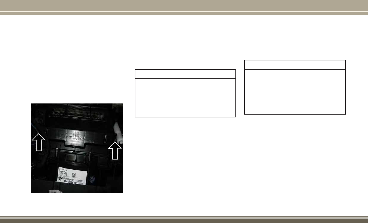
The A/C air filter is located in the fresh air
inlet behind the glove compartment. Perform
the following procedure to replace the filter:
1. Open the glove compartment and remove
all contents.
2. Push in on the sides of the glove compart-
ment and lower the door.
3. Pivot the glove compartment downward.
4. Disengage the two retaining tabs that se-
cure the filter cover to the HVAC housing,
and remove the cover.
5. Remove the A/C air filter by pulling it
straight out of the housing.
6. Install the A/C air filter with the arrow on
the filter pointing toward the floor. When
installing the filter cover, make sure the
retaining tabs fully engage the cover.
CAUTION!
The cabin air filter is identified with an
arrow to indicate airflow direction through
the filter. Failure to properly install the
filter will result in the need to replace it
more often.
7. Rotate the glove compartment door back
into position.
DEALER SERVICE
Your authorized dealer has the qualified ser-
vice personnel, special tools, and equipment
to perform all service operations in an expert
manner. Service Manuals are available which
include detailed service information for your
vehicle. Refer to these Service Manuals be-
fore attempting any procedure yourself.
NOTE:
Intentional tampering with emissions control
systems may void your warranty and could
result in civil penalties being assessed
against you.
WARNING!
You can be badly injured working on or
around a motor vehicle. Only do service work
for which you have the knowledge and the
proper equipment. If you have any doubt
about your ability to perform a service job,
take your vehicle to a competent mechanic.
Windshield Wiper Blades
Clean the rubber edges of the wiper blades and
the windshield periodically with a sponge or
soft cloth and a mild nonabrasive cleaner. This
will remove accumulations of salt or road film.
Operation of the wipers on dry glass for long
periods may cause deterioration of the wiper
blades. Always use washer fluid when using
the wipers to remove salt or dirt from a dry
windshield.
A/C Air Filter Retaining Tabs
SERVICING AND MAINTENANCE
178

Avoid using the wiper blades to remove frost
or ice from the windshield. Keep the blade
rubber out of contact with petroleum prod-
ucts such as engine oil, gasoline, etc.
NOTE:
Life expectancy of wiper blades varies depend-
ing on geographical area and frequency of use.
Poor performance of blades may be present with
chattering, marks, water lines or wet spots. If
any of these conditions are present, clean the
wiper blades or replace as necessary.
RAISING THE VEHICLE
In the case where it is necessary to raise the
vehicle, go to an authorized dealer or service
station.
TIRES
Tire Safety Information
Tire safety information will cover aspects of
the following information: Tire Markings, Tire
Identification Numbers, Tire Terminology and
Definitions, Tire Pressures, and Tire Loading.
Tire Markings
NOTE:
• P (Passenger) — Metric tire sizing is based
on U.S. design standards. P-Metric tires
have the letter “P” molded into the side-
wall preceding the size designation.
Example: P215/65R15 95H.
• European — Metric tire sizing is based on
European design standards. Tires de-
signed to this standard have the tire size
molded into the sidewall beginning with
the section width. The letter "P" is absent
from this tire size designation.
Example: 215/65R15 96H.
• LT (Light Truck) — Metric tire sizing is
based on U.S. design standards. The size
designation for LT-Metric tires is the same
as for P-Metric tires except for the letters
“LT” that are molded into the sidewall
preceding the size designation.
Example: LT235/85R16.
• Temporary spare tires are designed for
temporary emergency use only. Temporary
high pressure compact spare tires have the
letter “T” or “S” molded into the sidewall
preceding the size designation.
Example: T145/80D18 103M.
Tire Markings
1 — U.S. DOT
Safety Standards
Code (TIN)
4 — Maximum
Load
2 — Size Designa-
tion
5 — Maximum
Pressure
3 — Service De-
scription
6 — Treadwear,
Traction and Tem-
perature Grades
179

• High flotation tire sizing is based on U.S.
design standards and it begins with the
tire diameter molded into the sidewall.
Example: 31x10.5 R15 LT.
Tire Identification Number (TIN)
The TIN may be found on one or both sides of
the tire; however, the date code may only be
on one side. Tires with white sidewalls will
have the full TIN, including the date code,
located on the white sidewall side of the tire.
Look for the TIN on the outboard side of black
sidewall tires as mounted on the vehicle. If
the TIN is not found on the outboard side,
then you will find it on the inboard side of the
tire.
EXAMPLE:
DOT MA L9 ABCD 0301
DOT = Department of Transportation
– This symbol certifies that the tire is in compliance with the U.S. Department of Transportation tire safety standards and is ap-
proved for highway use
MA = Code representing the tire manufacturing location (two digits)
L9 = Code representing the tire size (two digits)
ABCD = Code used by the tire manufacturer (one to four digits)
03 = Number representing the week in which the tire was manufactured (two digits)
–03meansthe3rdweek
01 = Number representing the year in which the tire was manufactured (two digits)
– 01 means the year 2001
– Prior to July 2000, tire manufacturers were only required to have one number to represent the year in which the tire was manufac-
tured. Example: 031 could represent the 3rd week of 1981 or 1991
SERVICING AND MAINTENANCE
180

Tire Terminology And Definitions
Term Definition
B-Pillar
The vehicle B-Pillar is the structural member of the body located behind the front
door.
Cold Tire Inflation Pressure
Cold tire inflation pressure is defined as the tire pressure after the vehicle has not
been driven for at least three hours, or driven less than 1 mile (1.6 km) after sitting
for a minimum of three hours. Inflation pressure is measured in units of PSI (pounds
per square inch) or kPa (kilopascals).
Maximum Inflation Pressure
The maximum inflation pressure is the maximum permissible cold tire inflation pres-
sure for this tire. The maximum inflation pressure is molded into the sidewall.
Recommended Cold Tire Inflation Pressure
Vehicle manufacturer's recommended cold tire inflation pressure as shown on the tire
placard.
Tire Placard
A label permanently attached to the vehicle describing the vehicle’s loading capacity,
the original equipment tire sizes and the recommended cold tire inflation pressures.
181

Tire Loading And Tire Pressure
NOTE:
The proper cold tire inflation pressure is
listed on the driver’s side B-Pillar or the rear
edge of the driver's side door.
Tire And Loading Information Placard
This placard tells you important information
about the:
1. Number of people that can be carried in
the vehicle.
2. Total weight your vehicle can carry.
3. Tire size designed for your vehicle.
4. Cold tire inflation pressures for the front,
rear, and spare tires.
Loading
The vehicle maximum load on the tire must
not exceed the load carrying capacity of the
tire on your vehicle. You will not exceed the
tire's load carrying capacity if you adhere to
the loading conditions, tire size, and cold tire
inflation pressures specified on the Tire and
Loading Information placard in “Vehicle
Loading” in the “Starting And Operating”
section of this manual.
NOTE:
Under a maximum loaded vehicle condition,
gross axle weight ratings (GAWRs) for the
front and rear axles must not be exceeded.
Example Tire Placard Location (Door)
Example Tire Placard Location (B-Pillar)
Tire And Loading Information Placard
SERVICING AND MAINTENANCE
182

To determine the maximum loading condi-
tions of your vehicle, locate the statement
“The combined weight of occupants and
cargo should never exceed XXX kg or XXX lbs”
on the Tire and Loading Information placard.
The combined weight of occupants, cargo/
luggage and trailer tongue weight (if appli-
cable) should never exceed the weight refer-
enced here.
Steps For Determining Correct Load
Limit—
(1) Locate the statement “The com-
bined weight of occupants and cargo
should never exceed XXX kg or
XXX lbs.” on your vehicle's placard.
(2) Determine the combined weight of
the driver and passengers that will be
riding in your vehicle.
(3) Subtract the combined weight of
the driver and passengers from XXX kg
or XXX lbs.
(4) The resulting figure equals the
available amount of cargo and luggage
load capacity. For example, if “XXX”
amount equals 1400 lbs. and there
will be five 150 lb passengers in your
vehicle, the amount of available cargo
and luggage load capacity is 650 lbs.
(1400-750 (5x150) = 650 lbs.)
(5) Determine the combined weight of
luggage and cargo being loaded on the
vehicle. That weight may not safely
exceed the available cargo and lug-
gage load capacity calculated in Step
4.
(6) If your vehicle will be towing a
trailer, load from your trailer will be
transferred to your vehicle. Consult
this manual to determine how this
reduces the available cargo and lug-
gage load capacity of your vehicle.
Metric Example For Load Limit
For example, if “XXX” amount equals 635 kg
and there will be five 68 kg passengers in
your vehicle, the amount of available cargo
and luggage load capacity is 295 kg (635-
340 (5x68) = 295 kg) as shown in step 4.
NOTE:
• If your vehicle will be towing a trailer, load
from your trailer will be transferred to your
vehicle. The following table shows ex-
amples on how to calculate total load,
cargo/luggage, and towing capacities of
your vehicle with varying seating configu-
rations and number and size of occupants.
This table is for illustration purposes only
and may not be accurate for the seating
and load carry capacity of your vehicle.
• For the following example, the combined
weight of occupants and cargo should
never exceed 865 lbs (392 kg).
183

SERVICING AND MAINTENANCE
184

WARNING!
Overloading of your tires is dangerous.
Overloading can cause tire failure, affect
vehicle handling, and increase your stop-
ping distance. Use tires of the recom-
mended load capacity for your vehicle.
Never overload them.
Wheel And Wheel Trim Care
All wheels and wheel trim, especially alumi-
num and chrome plated wheels, should be
cleaned regularly using mild (neutral Ph)
soap and water to maintain their luster and to
prevent corrosion. Wash wheels with the
same soap solution recommended for the
body of the vehicle.
Your wheels are susceptible to deterioration
caused by salt, sodium chloride, magnesium
chloride, calcium chloride, etc., and other
road chemicals used to melt ice or control
dust on dirt roads. Use a soft cloth or sponge
and mild soap to wipe away promptly. Do not
use harsh chemicals or a stiff brush. They can
damage the wheel’s protective coating that
helps keep them from corroding and tarnish-
ing.
NOTE:
Many aftermarket wheel cleaners contain
strong acids or strong alkaline additives that
can harm the wheel surface.
CAUTION!
Avoid products or automatic car washes
that use acidic solutions or strong alkaline
additives or harsh brushes. These products
and automatic car washes may damage the
wheel's protective finish. Such damage is
not covered by the New Vehicle Limited
Warranty. Only car wash soap, MOPAR
Wheel Cleaner or equivalent is recom-
mended.
When cleaning extremely dirty wheels includ-
ing excessive brake dust, care must be taken
in the selection of tire and wheel cleaning
chemicals and equipment to prevent damage
to the wheels. Mopar Wheel Treatment or
Mopar Chrome Cleaner or their equivalent is
recommended or select a non-abrasive, non-
acidic cleaner for aluminum or chrome
wheels. Do not use any products on Dark
Vapor or Black Satin Chrome Wheels. They
will permanently damage this finish and such
damage is not covered by the New Vehicle
Limited Warranty.
CAUTION!
Do not use scouring pads, steel wool, a
bristle brush, metal polishes or oven
cleaner. These products may damage the
wheel's protective finish. Such damage is
not covered by the New Vehicle Limited
Warranty. Only car wash soap, MOPAR
Wheel Cleaner or equivalent is recom-
mended.
NOTE:
If you intend parking or storing your vehicle
for an extended period after cleaning the
wheels with wheel cleaner, drive your vehicle
for a few minutes before doing so. Driving the
vehicle and applying the brakes when stop-
ping will reduce the risk of brake rotor corro-
sion.
185

Dark Vapor Or Black Satin Chrome Wheels
CAUTION!
If your vehicle is equipped with Dark Vapor
or Black Satin Chrome wheels DO NOT
USE wheel cleaners, abrasives or polish-
ing compounds. They will permanently
damage this finish and such damage is not
covered by the New Vehicle Limited War-
ranty. USE ONLY MILD SOAP AND WATER
WITH A SOFT CLOTH. Used on a regular
basis; this is all that is required to main-
tain this finish.
Tire Chains (Traction Devices)
Due to limited clearance, tire chains or trac-
tion devices are not recommended.
CAUTION!
Damage to the vehicle may result if tire
chains are used.
Tire Rotation Recommendations
The tires on the front and rear of your vehicle
operate at different loads and perform differ-
ent steering, driving, and braking functions.
For these reasons, they wear at unequal rates.
These effects can be reduced by timely rota-
tion of tires. The benefits of rotation are
especially worthwhile with aggressive tread
designs such as those on all season type
tires. Rotation will increase tread life, help to
maintain mud, snow and wet traction levels,
and contribute to a smooth, quiet ride.
Refer to the “Maintenance Plan” for the
proper maintenance intervals. The reasons
for any rapid or unusual wear should be
corrected prior to rotation being performed.
The suggested rotation method is the “for-
ward cross” shown in the following diagram.
This rotation pattern does not apply to some
directional tires that must not be reversed.
DEPARTMENT OF
TRANSPORTATION
UNIFORM TIRE QUALITY
GRADES
The following tire grading categories
were established by the National High-
way Traffic Safety Administration. The
specific grade rating assigned by the
tire's manufacturer in each category is
shown on the sidewall of the tires on
your vehicle.
Tire Rotation
SERVICING AND MAINTENANCE
186
All passenger vehicle tires must con-
form to Federal safety requirements in
addition to these grades.
Treadwear
The Treadwear grade is a comparative
rating, based on the wear rate of the
tire when tested under controlled con-
ditions on a specified government test
course. For example, a tire graded
150 would wear one and one-half
times as well on the government
course as a tire graded 100. The rela-
tive performance of tires depends
upon the actual conditions of their
use, however, and may depart signifi-
cantly from the norm due to variations
in driving habits, service practices,
and differences in road characteristics
and climate.
Traction Grades
The Traction grades, from highest to
lowest, are AA, A, B, and C. These
grades represent the tire's ability to
stop on wet pavement, as measured
under controlled conditions on speci-
fied government test surfaces of as-
phalt and concrete. A tire marked C
may have poor traction performance.
WARNING!
The traction grade assigned to this
tire is based on straight-ahead brak-
ing traction tests, and does not in-
clude acceleration, cornering, hy-
droplaning, or peak traction
characteristics.
Temperature Grades
The Temperature grades are A (the
highest), B, and C, representing the
tire's resistance to the generation of
heat and its ability to dissipate heat,
when tested under controlled condi-
tions on a specified indoor laboratory
test wheel.
Sustained high temperature can cause
the material of the tire to degenerate
and reduce tire life, and excessive
temperature can lead to sudden tire
failure. The grade C corresponds to a
level of performance, which all pas-
senger vehicle tires must meet under
the Federal Motor Vehicle Safety Stan-
dard No. 109. Grades B and A repre-
sent higher levels of performance on
the laboratory test wheel, than the
minimum required by law.
WARNING!
The temperature grade for this tire is
established for a tire that is properly
inflated and not overloaded. Exces-
sive speed, under-inflation, or ex-
187

WARNING!
cessive loading, either separately or
in combination, can cause heat
buildup and possible tire failure.
STORING THE VEHICLE
If you will not be using your vehicle for more
than 21 days, you may want to take steps to
preserve your battery.
• Disengage the mini-fuse in the Power Dis-
tribution Center labeled IOD (Ignition Off-
Draw).
• Or disconnect the negative cable from the
battery.
• Anytime you store your vehicle, or keep it
out of service (i.e., vacation) for two weeks
or more, run the air conditioning system at
idle for about five minutes in the fresh air
and high blower setting. This will ensure
adequate system lubrication to minimize
the possibility of compressor damage when
the system is started again.
BODYWORK
Preserving The Bodywork
Washing
• Wash your vehicle regularly. Always wash
your vehicle in the shade using MOPAR Car
Wash, or a mild car wash soap, and rinse
the panels completely with clear water.
• If insects, tar, or other similar deposits
have accumulated on your vehicle, use
MOPAR Super Kleen Bug and Tar Remover
to remove.
• Use a high quality cleaner wax, such as
MOPAR Cleaner Wax to remove road film,
stains and to protect your paint finish. Take
care never to scratch the paint.
• Avoid using abrasive compounds and
power buffing that may diminish the gloss
or thin out the paint finish.
CAUTION!
• Do not use abrasive or strong cleaning
materials such as steel wool or scouring
CAUTION!
powder that will scratch metal and
painted surfaces.
• Use of power washers exceeding
1,200 psi (8,274 kPa) can result in
damage or removal of paint and decals.
Special Care
• If you drive on salted or dusty roads or if
you drive near the ocean, hose off the
undercarriage at least once a month.
• It is important that the drain holes in the
lower edges of the doors, rocker panels,
and trunk be kept clear and open.
• If you detect any stone chips or scratches
in the paint, touch them up immediately.
The cost of such repairs is considered the
responsibility of the owner.
• If your vehicle is damaged due to a colli-
sion or similar cause that destroys the
paint and protective coating, have your
vehicle repaired as soon as possible. The
cost of such repairs is considered the re-
sponsibility of the owner.
SERVICING AND MAINTENANCE
188

• If you carry special cargo such as chemi-
cals, fertilizers, de-icer salt, etc., be sure
that such materials are well packaged and
sealed.
• If a lot of driving is done on gravel roads,
consider mud or stone shields behind each
wheel.
• Use MOPAR Touch Up Paint on scratches
as soon as possible. Your authorized dealer
has touch up paint to match the color of
your vehicle.
INTERIORS
Seats And Fabric Parts
Use MOPAR Total Clean to clean fabric up-
holstery and carpeting.
WARNING!
Do not use volatile solvents for cleaning
purposes. Many are potentially flammable,
and if used in closed areas they may cause
respiratory harm.
Seat Belt Maintenance
Do not bleach, dye or clean the belts with
chemical solvents or abrasive cleaners. This
will weaken the fabric. Sun damage can also
weaken the fabric.
If the belts need cleaning, use a mild soap
solution or lukewarm water. Do not remove
the belts from the vehicle to wash them. Dry
with a soft cloth.
Replace the belts if they appear frayed or
worn or if the buckles do not work properly.
WARNING!
A frayed or torn belt could rip apart in a
collision and leave you with no protection.
Inspect the belt system periodically,
checking for cuts, frays, or loose parts.
Damaged parts must be replaced immedi-
ately. Do not disassemble or modify the
system. Seat belt assemblies must be re-
placed after a collision if they have been
damaged (i.e., bent retractor, torn web-
bing, etc.).
Plastic And Coated Parts
Use MOPAR Total Clean to clean vinyl
upholstery.
CAUTION!
•
Direct contact of air fresheners, insect
repellents, suntan lotions, or hand sanitiz-
ers to the plastic, painted, or decorated
surfaces of the interior may cause perma-
nent damage. Wipe away immediately.
• Damage caused by these type of prod-
ucts may not be covered by your New
Vehicle Limited Warranty.
Cleaning Plastic Instrument Cluster Lenses
The lenses in front of the instruments in this
vehicle are molded in clear plastic. When
cleaning the lenses, care must be taken to
avoid scratching the plastic.
1. Clean with a wet soft cloth. A mild soap
solution may be used, but do not use high
alcohol content or abrasive cleaners. If
soap is used, wipe clean with a clean
damp cloth.
2. Dry with a soft cloth.
189

Leather Parts
MOPAR Total Clean is specifically recom-
mended for leather upholstery.
Your leather upholstery can be best preserved
by regular cleaning with a damp soft cloth.
Small particles of dirt can act as an abrasive
and damage the leather upholstery and
should be removed promptly with a damp
cloth. Stubborn soils can be removed easily
with a soft cloth and MOPAR Total Clean.
Care should be taken to avoid soaking your
leather upholstery with any liquid. Please do
not use polishes, oils, cleaning fluids, sol-
vents, detergents, or ammonia-based clean-
ers to clean your leather upholstery. Applica-
tion of a leather conditioner is not required to
maintain the original condition.
NOTE:
If equipped with light colored leather, it
tends to show any foreign material, dirt, and
fabric dye transfer more so than darker col-
ors. The leather is designed to for easy clean-
ing, and FCA recommends MOPAR total care
leather cleaner applied on a cloth to clean the
leather seats as needed.
CAUTION!
Do not use Alcohol and Alcohol-based
and/or Ketone based cleaning products to
clean leather seats, as damage to the seat
may result.
SERVICING AND MAINTENANCE
190

TECHNICAL SPECIFICATIONS
VEHICLE IDENTIFICATION
NUMBER ..................192
BRAKESYSTEM.............192
WHEEL AND TIRE TORQUE
SPECIFICATIONS ............193
Torque Specifications ...........193
FUELREQUIREMENTS........193
2.0L And 2.4L Engine ...........193
Materials Added To Fuel .........194
FLUIDCAPACITIES ..........194
FLUIDS AND LUBRICANTS . . . .195
Engine ....................195
Chassis ....................196
MOPARACCESSORIES........196
Authentic Accessories By Mopar .....196
TECHNICAL SPECIFICATIONS
191

VEHICLE IDENTIFICATION
NUMBER
The Vehicle Identification Number (VIN) is
found on the left front corner of the instru-
ment panel, visible through the windshield.
This number also is stamped into the right
front body, on the right front seat crossmem-
ber under the carpet and the vehicle registra-
tion and title.
NOTE:
It is illegal to remove or alter the VIN.
BRAKE SYSTEM
Your vehicle is equipped with power assisted
brakes as standard equipment. In the event
power assist is lost for any reason (for ex-
ample, repeated brake applications with the
engine off), the brakes will still function.
However, the effort required to brake the
vehicle will be much greater than that re-
quired with the power system operating.
WARNING!
Riding the brakes can lead to brake failure
and possibly a collision. Driving with your
foot resting or riding on the brake pedal
can result in abnormally high brake tem-
peratures, excessive lining wear, and pos-
sible brake damage. You would not have
your full braking capacity in an emergency.
If either of the two hydraulic systems lose
normal capability, the remaining system will
still function with some loss of overall braking
effectiveness. This will be evident by in-
creased pedal travel during application and
greater pedal force required to slow or stop.
In addition, if the malfunction is caused by
an internal leak, as the brake fluid in the
master cylinder drops, the “Brake Warning
Light” will light.
Vehicle Identification Number
Right Front Body VIN Location
TECHNICAL SPECIFICATIONS
192
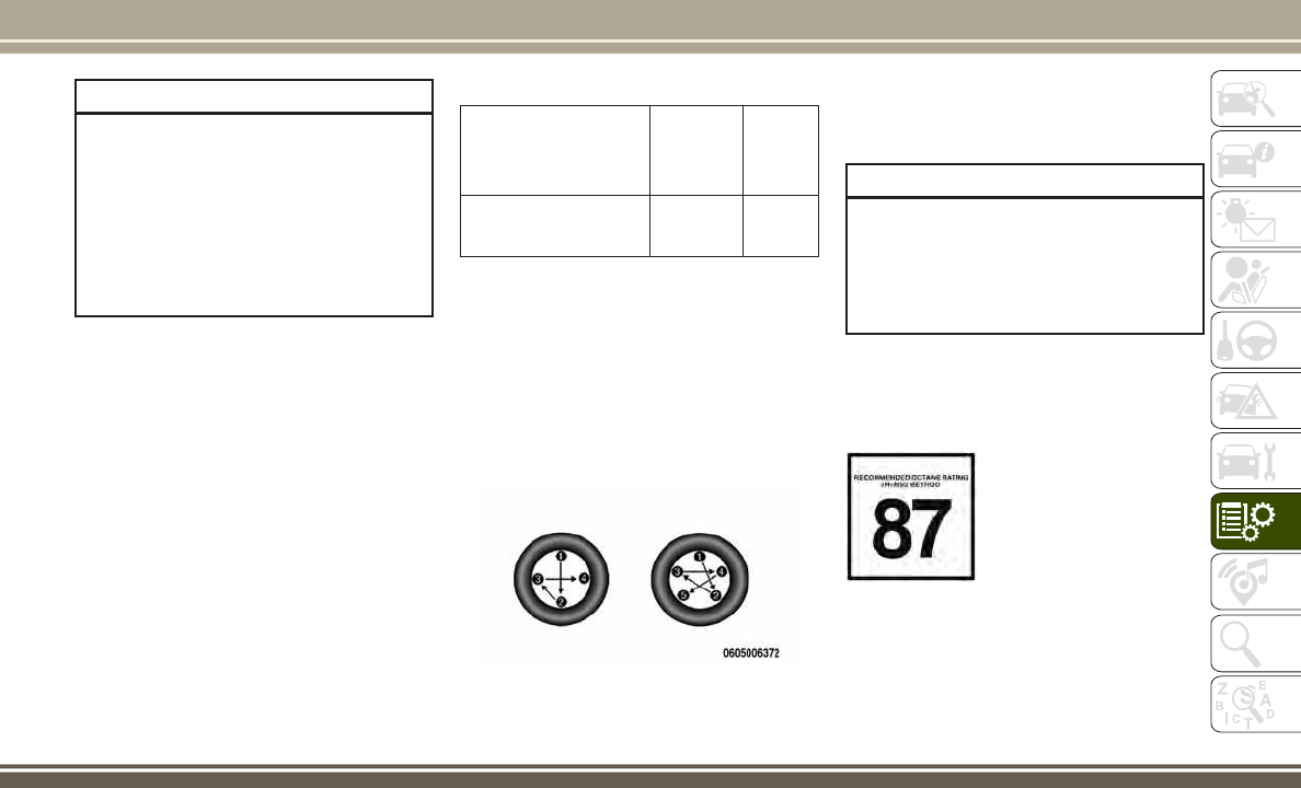
WARNING!
Driving a vehicle with the “Brake Warning
Light” on is dangerous. A significant de-
crease in braking performance or vehicle
stability during braking may occur. It will
take you longer to stop the vehicle or will
make your vehicle harder to control. You
could have a collision. Have the vehicle
checked immediately.
WHEEL AND TIRE TORQUE
SPECIFICATIONS
Proper lug nut/bolt torque is very important to
ensure that the wheel is properly mounted to
the vehicle. Any time a wheel has been re-
moved and reinstalled on the vehicle, the lug
nuts/bolts should be torqued using a properly
calibrated torque wrench.
Torque Specifications
Lug Nut/Bolt Torque **Lug Nut/
Bolt Size
Lug Nut/
Bolt
Socket
Size
100 Ft-Lbs (135 N·m)
M12 x
1.5
19 mm
**Use only your authorized dealer recom-
mended lug nuts/bolts and clean or remove
any dirt or oil before tightening.
Inspect the wheel mounting surface prior to
mounting the tire and remove any corrosion
or loose particles.
Tighten the lug nuts/bolts in a star pattern
until each nut/bolt has been tightened twice.
After 25 miles (40 km), check the lug nut/
bolt torque to be sure that all the lug nuts/
bolts are properly seated against the wheel.
WARNING!
To avoid the risk of forcing the vehicle off
the jack, do not tighten the lug nuts fully
until the vehicle has been lowered. Failure
to follow this warning may result in per-
sonal injury.
FUEL REQUIREMENTS
2.0L And 2.4L Engine
These engines are designed
to meet all emissions regu-
lations and provide opti-
mum fuel economy and
performance when using
high quality unleaded
“Regular” gasoline having
a posted octane number of 87 as specified by
Torque Patterns
193

the (R+M)/2 method. The use of higher octane
“Premium” gasoline is not required, as it will
not provide any benefit over “Regular” gasoline
in these engines.
While operating on gasoline with an octane
number of 87, hearing a light knocking sound
from the engine is not a cause for concern.
However, if the engine is heard making a
heavy knocking sound, see your dealer imme-
diately. Use of gasoline with an octane num-
ber lower than 87 can cause engine failure
and may void or not be covered by the New
Vehicle Limited Warranty.
Poor quality gasoline can cause problems
such as hard starting, stalling, and hesita-
tions. If you experience these symptoms, try
another brand of gasoline before considering
service for the vehicle.
Materials Added To Fuel
Designated TOP TIER
Detergent Gasoline
contains a higher level
of detergents to fur-
ther aide in minimiz-
ing engine and fuel
system deposits. When
available, the usage of
Top Tier Detergent gasoline is recommended.
Visit www.toptiergas.com for a list of TOP
TIER Detergent Gasoline Retailers.
Indiscriminate use of fuel system cleaning
agents should be avoided. Many of these
materials intended for gum and varnish re-
moval may contain active solvents or similar
ingredients. These can harm fuel system gas-
ket and diaphragm materials.
FLUID CAPACITIES
U.S. Metric
Fuel (Approximate)
13.6 Gallons 51 Liters
Engine Oil with Filter
2.0L and 2.4L Engine (SAE 5W-20, API Certified) 4.5 Quarts 4.26 Liters
Cooling System *
2.0L and 2.4L Engine (MOPAR Antifreeze/Engine Coolant 10 Year/150,000 Mile For-
mula or equivalent)
7.2 Quarts 6.8 Liters
* Includes heater and coolant recovery bottle filled to MAX level.
TECHNICAL SPECIFICATIONS
194

FLUIDS AND LUBRICANTS
Engine
Component Fluid, Lubricant, or Genuine Part
Engine Coolant We recommend you use MOPAR Antifreeze/Coolant 10 Year/150,000 Mile Formula OAT (Organic Additive
Technology) or equivalent meeting the requirements of FCA Material Standard MS.90032.
Engine Oil We recommend you use API Certified SAE 5W-20 Engine Oil, meeting the requirements of FCA Material
Standard MS-6395 such as MOPAR, Pennzoil, and Shell Helix. Refer to your engine oil filler cap for correct SAE
grade.
Engine Oil Filter We recommend you use MOPAR Engine Oil Filter or equivalent.
Spark Plugs We recommend you use MOPAR Spark Plugs.
Fuel Selection 87 Octane, 0-15% Ethanol.
CAUTION!
• Mixing of engine coolant (antifreeze)
other than specified Organic Additive
Technology (OAT) engine coolant (anti-
freeze), may result in engine damage
and may decrease corrosion protection.
Organic Additive Technology (OAT) en-
gine coolant is different and should not
be mixed with Hybrid Organic Additive
Technology (HOAT) engine coolant (anti-
CAUTION!
freeze) or any “globally compatible”
coolant (antifreeze). If a non-OAT engine
coolant (antifreeze) is introduced into
the cooling system in an emergency, the
cooling system will need to be drained,
flushed, and refilled with fresh OAT cool-
ant (conforming to MS.90032), by an
authorized dealer as soon as possible.
• Do not use water alone or alcohol-based
engine coolant (antifreeze) products. Do
not use additional rust inhibitors or an-
CAUTION!
tirust products, as they may not be com-
patible with the radiator engine coolant
and may plug the radiator.
• This vehicle has not been designed for
use with propylene glycol-based engine
coolant (antifreeze). Use of propylene
glycol-based engine coolant (antifreeze)
is not recommended.
195

Chassis
Component Fluid, Lubricant, or Genuine Part
Automatic Transmission (CVT) — If
Equipped
Use only MOPAR CVTF+4 Continuously Variable Transmission Fluid or equivalent. Failure to use the correct fluid
may affect the function or performance of your transmission.
Automatic Transmission (Six-
Speed) — If Equipped
Use only MOPAR SP-IV M Automatic Transmission Fluid or equivalent. Failure to use the correct fluid may affect
the function or performance of your transmission.
Manual Transmission — If
Equipped
We recommend you use MOPAR ATF+4 Automatic Transmission Fluid.
Rear Drive Assembly (RDA) We recommend you use MOPAR Gear & Axle Lubricant SAE 80W-90 API GL 5.
Power Transfer Unit (PTU) We recommend you use MOPAR Gear & Axle Lubricant SAE 80W-90 API GL 5.
Brake Master Cylinder We recommend you use MOPAR DOT 3, SAE J1703 should be used. If DOT 3, SAE J1703 brake fluid is not
available, then DOT 4 is acceptable.
Power Steering Reservoir We recommend you use MOPAR Power Steering Fluid +4, MOPAR ATF+4 Automatic Transmission Fluid.
MOPAR ACCESSORIES
Authentic Accessories By Mopar
In choosing Authentic Accessories you gain
far more than expressive style, premium pro-
tection, or extreme entertainment, you also
benefit from enhancing your vehicle with
accessories that have been thoroughly tested
and factory-approved.
The following highlights just some of the
many Authentic Jeep Accessories by Mopar
featuring a fit, finish, and functionality spe-
cifically for your Jeep Patriot.
For the full line of Authentic Jeep Accesso-
ries by Mopar, visit your local dealership or
online at mopar.com for U.S. residents and
mopar.ca for Canadian residents.
TECHNICAL SPECIFICATIONS
196

EXTERIOR:
• Camping Tent • Sunroof Air Deflector • Front Air Deflector
• Hitch Receiver • Rear Air Deflectors • Molded Splash Guards
• Fog Lights • Vehicle Cover • 16” Steel Wheels
• 17” Steel Wheels • 18” Black/Silver Wheels • Trailer Towing Accessories
• Tow Hooks • Valve Stem Caps • License Plate Frames
• Wheel Locks
INTERIOR:
• Carpet Floor Mats • Door Sill Guards • Bright Pedal Kit
• Slush Mats • Collapsible Tote • Cargo Mat
• Katzkin Leather Interiors • Cargo Tray • Cargo Nets
• Roadside Safety Kit • Shift Knob • Security Cover
ELECTRONICS:
• Kicker Speakers • Ambient Light Kit • Remote Start
• Electronic Vehicle Tracking System (EVTS)
CARRIERS:
• Canoe Carrier • Bike Carriers • Water Sports Carrier
• Roof Rack • Roof Basket • Roof Cargo Box
• Ski and Snowboard Carriers • Hitch-mounted Bike Carriers
NOTE:
All parts are subject to availability.
197

198

MULTIMEDIA
RADIO130................200
Clock Setting.................201
Equalizer, Balance And Fade .......201
Radio Operation ...............201
CD/DISC Operation .............201
Audio Jack Operation ............201
RADIO 130 WITH SATELLITE
RADIO ...................202
Clock Setting.................203
Equalizer, Balance And Fade .......203
Radio Operation ...............203
SiriusXM Satellite Radio ..........204
CD/DISC Operation .............204
Audio Jack Operation ............205
UCONNECT 430/430N .......206
Clock Setting.................207
Menu .....................207
Equalizer, Balance And Fade .......207
Radio Operation ...............208
CD/DVD Disc Operation ..........209
Audio Jack Operation ............209
Hard Disk Drive (HDD) Operation . . . .210
Cleaning Your Touchscreen Radio . . . .212
Garmin Navigation .............212
Main Navigation Menu ...........213
Following Your Route ............214
SIRIUSXM SATELLITE RADIO/
TRAVELLINK...............214
SiriusXM Travel Link (Uconnect 430N
Only)......................218
CYBERSECURITY............218
TIPS CONTROLS AND GENERAL
INFORMATION..............219
Steering Wheel Audio Controls ......219
Reception Conditions ............220
Care And Maintenance ...........220
Anti-theft Protection ............220
AUX/USB/MP3 CONTROL — IF
EQUIPPED.................221
BLUETOOTH STREAMING
AUDIO ...................221
UCONNECT PHONE ..........222
Phone Pairing ................222
Phonebook ..................223
Making A Phone Call ............224
Receiving A Call — Accept (And End). .224
Mute (Or Unmute) Microphone During
Call ......................224
Transfer Ongoing Call Between Handset And
Vehicle ....................224
Changing The Volume ...........224
UCONNECT VOICE COMMAND. .225
Voice Command Operation.........225
Voice Text Reply ..............228
MULTIMEDIA
199

RADIO 130
Uconnect 130
1 — CD Eject Button
2 — SEEK Down Button
3 — SEEK Up Button
4 — AM/FM Button
5 — DISC Mode Button
6 — AUX Mode Button
7 — Rewind Button
8 — Fast Forward Button
9 — Set Clock Button
10 — Audio Settings/Rotate To Tune
11 — Radio Sales Code
12 — Audio Jack
13 — Set Preset/CD Random Play
14 — Station Presets Buttons
15 — ON/OFF/Rotate For Volume
MULTIMEDIA
200

NOTE:
• Your radio has many features that add to
the comfort and convenience for you and
your passengers.
•
Some of these radio features should not be
used when driving because they take your
eyes from the road or your attention from
driving.
Clock Setting
1. Push and hold the TIME button until the
hours blink.
2. Turn the TUNE/SCROLL control knob to
set the hours.
3. Push the TUNE/SCROLL control knob un-
til the minutes begin to blink.
4. Turn the TUNE/SCROLL control knob to
set the minutes.
5. Push the TUNE/SCROLL control knob to
save the changes.
6. Push any button/knob or wait five seconds
to exit.
Equalizer, Balance And Fade
1. Push the TUNE/SCROLL control knob and
“BASS” will display.
2. Rotate the TUNE/SCROLL control knob to
select the desired setting.
3.
Continue pushing the TUNE/SCROLL con-
trol knob to display and set “MID RANGE,”
“TREBLE,” “BALANCE” and “FADE.”
Radio Operation
Seek Up/Down Buttons
• Push the seek up or down button to seek
through radio stations in AM or FM bands.
• Hold either button to bypass stations with-
out stopping.
Store Radio Presets Manually
• Tune to the desired station.
•
Push the SET/RND or SET (depending on the
radio) button once and SET 1 will show in the
display. Then select a preset button (1–6).
• A second station may be added to each
push button. Push the SET/RND or SET
(depending on the radio) button twice and
SET 2 will show in the display. Then select
a preset button (1–6).
CD/DISC Operation
Seek Up/Down Buttons
• Push to seek through CD tracks.
• Hold either button to bypass tracks with-
out stopping.
SET/RND Or RND (Depending On Radio) Button
(Random Play)
• Push this button while the CD is playing to
activate Random Play.
• This feature plays the selections on the CD
in random order to provide an interesting
change of pace.
Audio Jack Operation
The AUX/Audio Jack provides a means to
connect a portable audio device, such as an
MP3 player or an iPod, to the vehicle’s sound
system. This requires the use of a 3.5 mm
stereo audio patch cable.
Pushing the AUX button will change the mode to
auxiliary device if the Audio Jack is connected,
allowing the music from your portable device to
play through the vehicle's speakers.
The functions of the portable device are con-
trolled using the device buttons, not the but-
tons on the radio. However, the volume may
be controlled using the radio or portable de-
vice.
201

RADIO 130 WITH SATELLITE RADIO
Uconnect 130 With SiriusXM Satellite Radio
1 — CD Eject Button
2 — SEEK Down Button
3 — SEEK Up Button
4 — Voice Command Button
5 — Uconnect Phone Button
6 — Station Info Button
7 — Rewind Button
8 — Fast Forward Button
9 — Set Clock Button
10 — Audio Settings/Rotate To Tune
11 — Radio Sales Code
12 — Audio Jack
13 — Set Preset/CD Random Play
14 — Station Preset Buttons
15 — ON/OFF/Rotate For Volume
16 — AM/FM Mode Button
17 — List Folders On A CD
18 — Satellite Radio Button
19 — Music Type Button
20 — DISC Mode Button
21 — Set Up Function Button
MULTIMEDIA
202

NOTE:
• Your radio may not be equipped with the
Uconnect Voice Command and Uconnect
Phone features. To determine if your radio
has these features, push the Voice Com-
mand button on the radio. You will hear a
voice prompt if you have the feature, or see
a message on the radio stating “Uconnect
Phone not available” if you do not.
• Your radio has many features that add to
the comfort and convenience of you and
your passengers. Some of these radio fea-
tures should not be used when driving
because they take your eyes from the road
or your attention from driving.
Clock Setting
1. Push and hold the TIME button until the
hours blink.
2. Turn the TUNE/SCROLL control knob to
set the hours.
3. Push the TUNE/SCROLL control knob un-
til the minutes begin to blink.
4. Turn the TUNE/SCROLL control knob to
set the minutes.
5. Push the TUNE/SCROLL control knob to
save the changes.
6. Push any button/knob or wait five seconds
to exit.
Equalizer, Balance And Fade
1. Push the TUNE/SCROLL control knob and
“BASS” will display.
2. Rotate the TUNE/SCROLL control knob to
select the desired setting.
3. Continue pushing the TUNE/SCROLL
control knob to display and set “MID
RANGE,” “TREBLE,” “BALANCE” and
“FADE.”
Radio Operation
Seek Up/Down Buttons
• Push the seek up or down button to seek
through radio stations in AM, FM, or SAT
bands.
• Hold either button to bypass stations with-
out stopping.
Store Radio Presets Manually
• Tune to the desired station.
• Push the SET/RND or SET (depending on
the radio) button once and SET 1 will show
in the display. Then select a preset button
(1–6).
• A second station may be added to each
push button. Push the SET/RND or SET
(depending on the radio) button twice and
SET 2 will show in the display. Then select
a preset button (1–6).
Music Type
NOTE:
The Music Type function only operates when
in FM mode.
• Push the MUSIC TYPE button to activate
this mode. Push the MUSIC TYPE button
again or turn the TUNE/SCROLL control
knob to select the desired music type
(Adult Hits, Country, Jazz, Oldies, Rock,
etc.).
• When a music type is chosen and the
Music type is displayed, push either SEEK
button and the radio will only search for
stations with the selected music type.
203

SETUP Button
• Pushing the SETUP button allows you to
select between items that are available in
that particular mode.
• Turn the TUNE/SCROLL control knob to
scroll through the entries. Push the
AUDIO/SELECT button to select an entry
and make changes.
SiriusXM Satellite Radio
SiriusXM services require subscriptions, sold
separately after the 12-month trial included
with the new vehicle purchase. If you decide
to continue your service at the end of your trial
subscription, the plan you choose will automati-
cally renew and bill at then-current rates until
you call SiriusXM at 1-866-635-2349 to can-
cel. See SiriusXM Customer Agreement for
complete terms at www.siriusxm.com. All
fees and programming subject to change. Our
satellite service is available only to those at
least 18 and older in the 48 contiguous USA
and D.C. Our Sirius satellite service is also
available in PR (with coverage limitations).
Our Internet radio service is available
throughout our satellite service area and in
AK and HI. ©2016 Sirius XM Radio Inc.
Sirius, XM and all related marks and logos are
trademarks of Sirius XM Radio Inc.
SiriusXM Satellite Radio gives you over
130 channels, including 100% commercial-
free music from nearly every genre, plus all
your favorite sports, news, talk and entertain-
ment channels – all with crystal clear, coast-
to-coast coverage, all in one place and all at
your fingertips.
• To access SiriusXM Satellite Radio, push
the SAT button on the faceplate.
CD/DISC Operation
Seek Up/Down Buttons
• Push to seek through CD tracks.
• Hold either button to bypass tracks with-
out stopping.
SET/RND or RND (Depending On Radio) Button
(Random Play)
• Push this button while the CD is playing to
activate random play.
• This feature plays the selections on the CD
in random order to provide an interesting
change of pace.
LIST Button
• Push the LIST button to bring up a list of
all folders on the CD. Scroll up or down the
list by turning the TUNE/SCROLL control
knob.
• To select a folder from the list, push the
TUNE/SCROLL control knob and the radio
will begin playing the files contained in
that folder.
MULTIMEDIA
204

Audio Jack Operation
The AUX/Audio Jack provides a means to
connect a portable audio device, such as an
MP3 player or an iPod, to the vehicle’s sound
system. This requires the use of a 3.5 mm
stereo audio patch cable.
Pushing the AUX button will change the
mode to auxiliary device if the Audio Jack is
connected, allowing the music from your por-
table device to play through the vehicle's
speakers.
The functions of the portable device are con-
trolled using the device buttons, not the but-
tons on the radio. However, the volume may
be controlled using the radio or portable de-
vice.
205

UCONNECT 430/430N
Uconnect 430/430N
1 — Voice Command Button
2 — Open/Close Display
3 — MENU Button
4 — AUDIO Settings Button
5 — Internal Hard Drive Button
6 — USB Port
7 — Audio Jack
8 — Radio Sales Code
9 — ON/OFF/Rotate For Volume
10 — Select MEDIA Mode Button
11 — RADIO Mode Button
12 — Uconnect Phone Button
MULTIMEDIA
206

NOTE:
•
Your radio may not be equipped with the
Uconnect Voice Command and Uconnect
Phone features. To determine if your radio
has these features, push the Voice Command
button on the radio. You will hear a voice
prompt if you have the feature, or see a
message on the radio stating “Uconnect
Phone not available” if you do not.
• Your radio has many features that add to
the comfort and convenience of you and
your passengers. Some of these radio fea-
tures should not be used when driving
because they take your eyes from the road
or your attention from driving.
Clock Setting
1. Turn the radio on, then press the screen
where the time is displayed.
2. Press the “User Clock” button on the
touchscreen or the time display (Naviga-
tion radio only).
3. To adjust the hours, press either the “Hour
Forward” or “Hour Backward” button on
the touchscreen.
4. To adjust the minutes, press either the
“Minute Forward” or “Minute Backward”
button on the touchscreen.
5. To save the new time setting, press the
screen where the word “Save” is
displayed.
Menu
• Push the MENU button on the faceplate to
access the System Setup menu and the
My Files menu.
• Push the MENU button on the faceplate in
an active mode (SAT, CD, AUX, etc.) to
change mode specific settings.
Equalizer, Balance And Fade
Audio Control Menu
• Push the AUDIO button on the faceplate
on the right side of the radio.
• Use either the “arrow” buttons on the
touchscreen or the sliders to adjust BASS,
MID, and/or TREBLE.
• Press the “BAL/FADE” button on the
touchscreen and use either the “arrow”
buttons on the touchscreen or the cross-
hair to change Balance and Fade. The
“Center” button on the touchscreen resets
the settings.
Display Settings
• Push the MENU button on the faceplate
and press the “Display Settings” button on
the touchscreen to access the Display Set-
tings menu.
Audio Control Menu
Display Settings
207
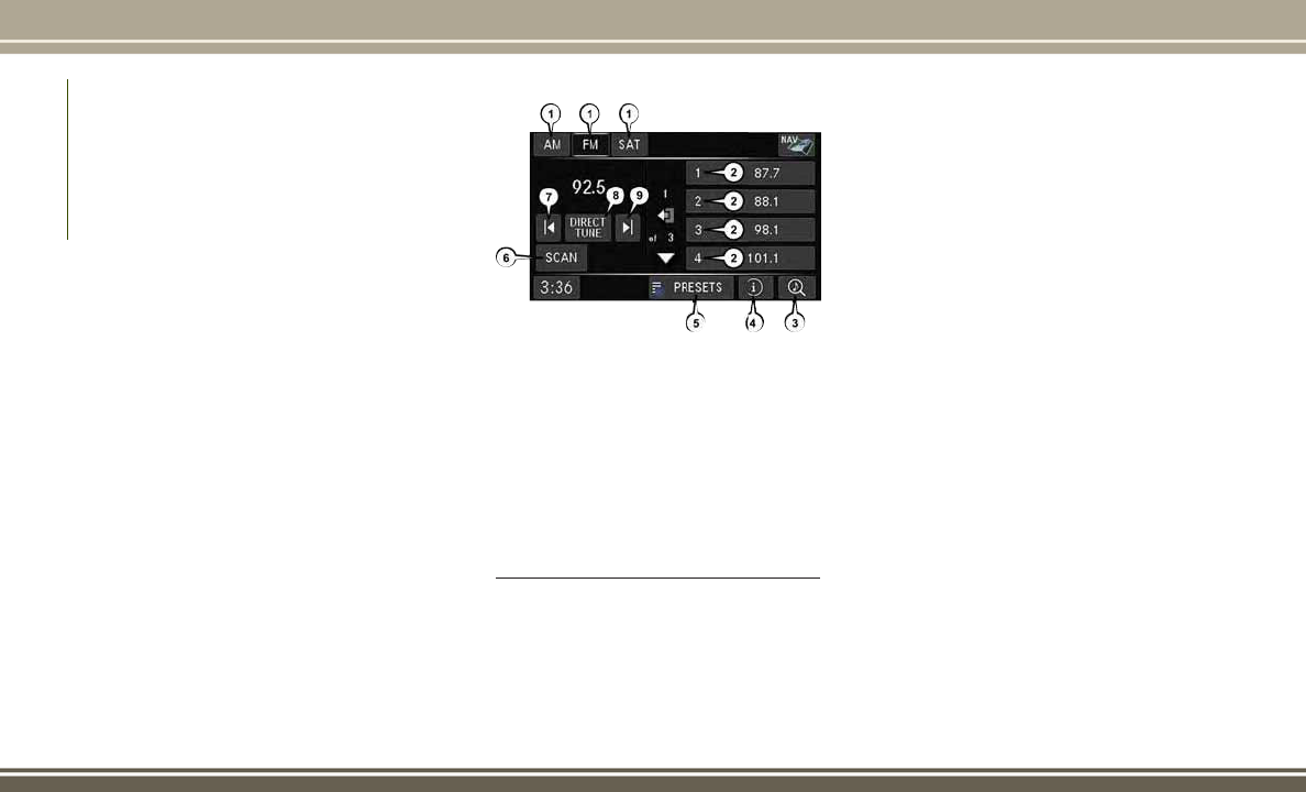
• Select the “Daytime Colors” button on the
touchscreen to switch to manual daytime
mode and to adjust the brightness of the
display using daytime colors.
• Select the “Nighttime Colors” button on
the touchscreen to switch to manual
nighttime mode and to adjust the bright-
ness of the display using nighttime colors.
• Select the “Auto Color Mode” button on
the touchscreen to switch to automatic
daytime/nighttime mode and to control
the brightness of the display using the
dimmer switch of the vehicle.
• Press the “Exit” button on the touch-
screen to save your settings.
Radio Operation
• To access Radio Mode, push the RADIO
button on the left side of the faceplate,
then press the “AM,” “FM” or “SAT” but-
ton on the touchscreen to select the band.
Seek Up/Seek Down
• Press the “SEEK UP” or “SEEK DOWN”
buttons on the touchscreen to seek
through radio stations in AM, FM, or SAT
bands. Hold either seek button to bypass
stations without stopping.
Store Radio Presets Manually
• Select the radio band by pressing either
the “AM,” “FM,” or “SAT” button on the
touchscreen.
• Find the station to store by either pressing
the “SEEK UP” or “SEEK DOWN” buttons
on the touchscreen, pressing the “Scan”
button on the touchscreen, or by using the
“Direct Tune” button on the touchscreen.
•
Once the desired station is found, press and
hold one of the “PRESETS” buttons on the
touchscreen in the list to the right, until the
preset key flashes and the station text on the
button on the touchscreen changes.
NOTE:
If the Presets are not visible on the right side
of the screen, press the “PRESETS” button
on the touchscreen.
Radio Operation
1 — Radio Tuner Tabs
2 — Individual Presets
3 — Search/Browse
4 — Radio Station/Track Info
5 — Sort Presets
6 — Station Scan
7 — Seek Down
8 — Direct Tune
9 — Seek Up
MULTIMEDIA
208

CD/DVD Disc Operation
• Push the MEDIA button on the faceplate
to display the media source tabs at the top
of the screen. Select the source by press-
ing the “HDD,” “DISC” or “AUX” media
source button on the touchscreen.
NOTE:
Your Touchscreen Radio will usually auto-
matically switch to the appropriate mode
when something is first connected or inserted
into the system.
Insert A CD/DVD Disc
• To insert a disc, push the LOAD button on
the faceplate.
• With the printed side upwards, insert the
disc into the disc slot of the radio. The
radio pulls the disc in automatically and
closes the flip screen. The radio selects
the appropriate mode after the disc is
recognized, and starts playing the first
track. The display shows “Reading...” dur-
ing this process.
Seek Up/Seek Down
• Push the SEEK UP or SEEK DOWN but-
tons on the faceplate to seek through
tracks in Disc Mode. Holding the SEEK UP
button on the touchscreen will fast forward
through the track until the beginning of
the track is reached; if still held it will
fast-forward through the next sequential
track(s) (if random play mode is not active)
until released. Holding the SEEK DOWN
button on the touchscreen will fast-reverse
through the track until the beginning of
the track is reached; if still held it will
fast-reverse through the next sequential
track(s) (if random play mode is not active)
until released.
Audio Jack Operation
The AUX/Audio Jack provides a means to
connect a portable audio device, such as an
MP3 player or an iPod, to the vehicle’s sound
system. This requires the use of a 3.5 mm
stereo audio patch cable.
• Push the MEDIA button on the faceplate
then the “AUX” button on the touchscreen
to change the mode to auxiliary device if
the Audio Jack is connected, allowing the
music from your portable device to play
through the vehicle's speakers.
CD/DVD Disc Operation
1 — Media Source Tabs
2 — Folder/Track
3 — Open Folder
4 — Track Information
5 — Sort Tracks
6 — Track Scan
7 — Seek Down
8 — Play/Pause
9 — Seek Up
209

NOTE:
The functions of the portable device are con-
trolled using the device itself, not the buttons
on the radio. However, the volume may be
controlled using the radio or portable device.
Hard Disk Drive (HDD) Operation
• The Hard Disk Drive (HDD) mode gives you
access to the audio files on the internal
hard disk drive. It functions similar to a CD
player, with the exception that the internal
HDD can hold more tracks.
• It is also possible to import display pic-
tures to the internal hard disk drive. The
pictures can be displayed on the right half
of the radio screen.
• Before using the HDD mode, you will need
to copy songs and pictures to the internal
hard drive. Songs and pictures can be
added to the hard drive by using a CD or
USB device (e.g. thumb drive or memory
stick).
NOTE:
• HDD supports only .jpg/JPEG formats for
photos.
• WMA/MP3 Files and selective songs from
a CD can also be added to the HDD. See
the Uconnect Owner’s Manual Supple-
ment for more information.
Copying Music From CD
• Push the LOAD button on the faceplate.
• Insert a disc, then push the MY FILES
button on the faceplate. Select the “MY
MUSIC” button on the touchscreen.
• Press the “Add Music Files to HDD” but-
ton on the touchscreen, then press the
“Disc” button on the touchscreen in the
next screen to start the process.
NOTE:
• You might need to select the folder or title
depending on the CD, then push “DONE”
to start the copy process.
• The copy progress is shown in the lower
left corner of the screen.
Copying Music From USB
• The USB port on the radio face plate
allows you to copy files to your hard drive.
To access, lift up on the cover.
• Insert a USB device (e.g. thumb drive or
memory stick), then select the “MY MU-
SIC” button on the touchscreen.
• Press the “Add Music Files to HDD” but-
ton on the touchscreen, then press the
“Front USB” button on the touchscreen in
the next screen.
Copying Music From CD
MULTIMEDIA
210

• Select the folders or titles you would like
to copy, then press the “SAVE” button on
the touchscreen to start the copy process.
• To copy all of the titles, press the “ALL”
button on the touchscreen then press the
“SAVE” button on the touchscreen.
NOTE:
The copy progress is shown in the lower left
corner of the screen.
Copying Pictures To The HDD
• Insert either a CD or a USB device contain-
ing your pictures in JPEG format.
• Push the MY FILES button on the face-
plate.
• Press the “My Pictures” button on the
touchscreen to get an overview of the cur-
rently stored images, then press the “Add”
button on the touchscreen.
• Press the “Disc” or “USB” button on the
touchscreen, then select the folders or
pictures you wish to copy to the HDD. Use
the “PAGE” buttons on the touchscreen to
page through the list of pictures.
•
Press the desired pictures or press the “All”
button on the touchscreen for all pictures.
Confirm your selections by pressing the
“SAVE” button on the touchscreen.
NOTE:
The copy progress is shown in the lower left
corner of the screen.
Display A Picture On The Radio Screen
• Once the import is complete, the pictures
will then be available in the “MY PIC-
TURES” screen.
• Push the MY FILES button on the face-
plate, then press the “My Pictures” button
on the touchscreen. Press the desired pic-
ture, press the “Set as Picture View” but-
ton on the touchscreen and then press the
“Exit” button on the touchscreen. Lastly
push the MENU button on the faceplate
and press the “Picture View” button on the
touchscreen to display the chosen picture
on the radio screen.
NOTE:
• A check mark in the My Pictures screen
indicates the currently used picture.
• You can also delete pictures by pressing
the “Delete” button on the touchscreen.
Playing Music From The HDD
• Push the MEDIA button on the faceplate
to display the media source tabs at the top
of the screen. Press the “HDD” button on
the touchscreen. Press the desired track
button on the touchscreen to play or press
Copying Music From USB
Copying Pictures To The HDD
211

the “SEARCH/BROWSE” button on the
touchscreen to search by artist, by album,
by song, by genre, from a folder, or from
Favorites.
Cleaning Your Touchscreen Radio
• If necessary, use a dry micro fiber lens
cleaning cloth dampened with a cleaning
solution such as isopropyl alcohol or an
isopropyl alcohol and water solution ratio
of 50:50. Always follow the solvent manu-
facturer's precautions and directions.
CAUTION!
Do not spray any liquid or caustic chemi-
cals directly on the screen. Use a clean
and dry micro fiber lens cleaning cloth to
clean the touchscreen.
Garmin Navigation
• Uconnect 430N integrates Garmin’s
consumer-friendly navigation into your ve-
hicle. Garmin Navigation includes a data-
base with over six million points of inter-
est.
• Press the “NAV” button in the upper right
corner of the touchscreen to access the
Navigation system.
Changing The Navigation Voice Prompt Volume
1. Program a destination.
2. While traveling on your route, press the
upper left area of the map screen where
your next turn is displayed.
3. The navigation system will then repeat the
distance to your next turn.
4. While the navigation system is speaking,
use the ON/OFF VOLUME rotary knob to
adjust the volume to a comfortable level.
Please note the volume setting for Navi-
gation Voice Prompt is different than the
audio system.
Playing Music From The HDD
Browsing Music From The HDD
Garmin Navigation
MULTIMEDIA
212

NOTE:
For your own safety and the safety of others, it
is not possible to use certain features while
the vehicle is in motion.
Main Navigation Menu
Finding Points Of Interest
• From the main Navigation menu, press the
“Where To?” button on the touchscreen,
then press the “Points of Interest” button
on the touchscreen.
• Select a category, then a subcategory, if
necessary.
• Select your destination and press the “Go”
button on the touchscreen.
Finding A Place By Spelling The Name
• From the main navigation menu, press the
“Where To?” button on the touchscreen.
Next, press the “Points of Interest” button
on the touchscreen then press the “Spell
Name” button on the touchscreen.
• Enter the name of your destination.
• Press the “Done” button on the touch-
screen.
• Select your destination and press the “Go”
button on the touchscreen.
Entering A Destination Address
• From the main navigation menu, press the
“Where To?” button on the touchscreen,
then press the “Address” button on the
touchscreen.
• Follow the on-screen prompts to enter the
address, then press the “Go” button on
the touchscreen.
Setting Your Home Location
• From the main navigation menu, press the
"Tools" icon. Select the "My Data" folder
icon, and then select "Set Home Loca-
tion."
• You may enter your address directly, use
your current location as your home ad-
dress, or choose from recently found
locations.
Edit Home Location
• From the main Navigation menu press the
“Where To?” button on the touchscreen,
then press the "Tools" icon. Next, press the
"My Data" folder.
• You may enter a new address directly, use
your current location or choose from re-
cently found locations.
Go Home
• A Home location must be saved in the
system. From the Main Navigation menu,
press the “Where To?” button on the
touchscreen, then press the “Go Home”
button on the touchscreen.
Main Navigation Menu
213

Following Your Route
Your route is marked with a magenta line on
the map. If you depart from the original route,
your route is recalculated. A speed limit icon
could appear as you travel on major road-
ways.
Adding A Via Point
To add a stop between the current location
and the end destination (Via Point), you must
be navigating a route.
• Press the “back arrow” icon multiple
times to return to the main navigation
menu.
• Press the “Where To?” button on the
touchscreen, then search for the addi-
tional stop. Select the destination you
wish to add from the given search results.
• Press the “Go” button on the touchscreen,
then press "Add as a Via Point" button on
the touchscreen and press the "Done" but-
ton on the touchscreen.
Taking A Detour
To take a detour, you must be navigating a
route.
• Press the “back arrow” icon button on the
touchscreen multiple times to return to
the main navigation menu.
• Press the “Detour” button on the
touchscreen.
NOTE:
If the route you are currently taking is the
only reasonable option, the device might not
calculate a detour.
Acquiring Satellites
The GPS Satellite strength bars indicate the
strength of your satellite reception.
• Acquiring satellite signals can take a few
minutes. When at least one of the bars is
green, your device has acquired satellite
signals.
• You may experience delays receiving sat-
ellite signals when in areas with an ob-
structed view to the sky, such as garages,
tunnels, or large cities with tall buildings.
SIRIUSXM SATELLITE
RADIO/TRAVEL LINK
SiriusXM Travel Link requires a subscription,
sold separately after the five year trial sub-
scription included with your vehicle purchase
and is ONLY available in the United States.
Following Your Route
1 — Distance To Next Turn
2 — Current Location
3 — Zoom In
4 — Zoom Out
5 — Current Speed
6 — Drag Map For Different View
7 — Your Location On The Map
8 — Estimated Time Of Arrival
9 — Navigation Main Menu
MULTIMEDIA
214

To access SiriusXM Satellite Radio, push the
RADIO/MEDIA or RADIO button on the face-
plate, then press the “SAT” button on the
touchscreen.
The following describes features that are
available when in SiriusXM Satellite Radio
mode.
Info
• Press the “i” button on the touchscreen to
view detailed information about the cur-
rent SiriusXM Satellite channel.
SiriusXM Parental Controls
• SiriusXM offers the option to permanently
block selected channels. Call
1-888-539-7474 and request the Family
Package.
• Uconnect 430/430N: Push the MENU but-
ton on the faceplate while in SiriusXM
Satellite Radio Mode, then press the
“Channel Lock” to enable and/or disable
desired channels. The SEEK and SCAN
function will then only display channels
without Channel lock.
Search/Browse
• Press the “magnifying glass” button on
the touchscreen to search/browse the
SiriusXM channel listing by Favorites and
Categories such as Song, Artist and Chan-
nel Name. The Search/Browse also allows
you manage your Favorites.
SiriusXM Satellite Radio Favorites (SAT Favor-
ites)
You can save 50 favorite songs and 50 favor-
ite artists.
• Press the “add favorite” button on the
touchscreen to add either the song or the
artist of the currently playing program to
the SAT Favorites list. The favorite star will
appear in the upper right corner, below the
SAT button on the touchscreen.
You will see a favorite star indicator in the
upper right side of the screen below the SAT
button on the touchscreen and a pop up will
alert you that a favorite song or artist is
currently playing on one of the SiriusXM sat-
ellite radio channels.
SAT Browse
Manage SAT Favorites
215

NOTE:
Refer to your Uconnect Owner’s Manual
Supplement for more information.
Display SAT Favorites List
• Press the “Search/Browse” button on the
touchscreen and select “Favorites” from
the SAT Browse screen.
• Press the desired favorites button on the
touchscreen to switch the SAT tuner to the
corresponding channel.
You may use the “LIST” button on the touch-
screen to toggle between:
• Favorite Songs
• Favorite Artists
• Currently playing favorites
Replay
• While you are in SAT mode, you can replay
44 minutes of the current SiriusXM chan-
nel (when the channel is changed, this
audio buffer is erased). Push the REPLAY
button to listen to the stored audio.
• You can press the on-screen controls to
pause and rewind audio playback, press
the SCAN button to preview each of the
tracks stored in the buffer, or select a track
from the list.
• The time displayed below the bar indi-
cates how much time is present between
the current buffer play position and the
live broadcast.
Favorite Artist Alert
Sat Favorites Browse
Sat Favorites Artist
Sat Favorites Replay
MULTIMEDIA
216

Replay Option Option Description
Play/Pause Press to pause content playback. Press “Pause/Play” again to resume playback.
Rewind/RW Rewinds the channel content in steps of five seconds. Press and hold to rewind continuously, then release to begin
playing content at that point.
Fast Forward/FW Forwards the content, and works similarly to Rewind/RW. However, Fast Forward/FW can only be used when content
has been previously rewound.
Replay Time Displays the amount of time in the upper center of the screen by which your content lags the live channel.
Live Resumes playback of live content at any time while replaying rewound content.
217
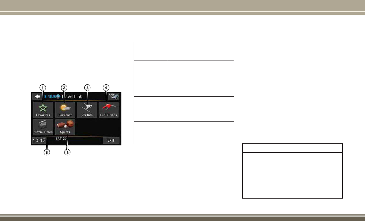
SiriusXM Travel Link (Uconnect 430N
Only)
NOTE:
SiriusXM Travel Link requires a subscription,
sold separately after the five year trial sub-
scription included with your vehicle purchase
and is ONLY available in the United States.
SiriusXM Travel Link brings a wealth of useful
information into your vehicle, right to your
fingertips.
• To access Travel Link, push the MENU
button on the faceplate, then the “Travel
Link” button on the touchscreen.
1 – Favorites
View and store your favorite
location, theater and sport
teams for quick access.
2 – Forecast
View detailed weather condi-
tions, forecasts and ski/
snowboarding conditions at
resorts.
3 – Ski Info
View ski and snowboarding
conditions at ski resorts.
4 – Fuel Prices
View detailed price informa-
tion for fuel stations.
5 – Movies
View information on movies
that are playing at theaters.
6 – Sports
View sports scores and up-
coming events for all major
sports.
CYBERSECURITY
Your vehicle may be a connected vehicle and
may be equipped with both wired and wire-
less networks. These networks allow your
vehicle to send and receive information. This
information allows systems and features in
your vehicle to function properly.
Your vehicle may be equipped with certain
security features to reduce the risk of unau-
thorized and unlawful access to vehicle sys-
tems and wireless communications. Vehicle
software technology continues to evolve over
time and FCA US LLC, working with its sup-
pliers, evaluates and takes appropriate steps
as needed. Similar to a computer or other
devices, your vehicle may require software
updates to improve the usability and perfor-
mance of your systems or to reduce the po-
tential risk of unauthorized and unlawful ac-
cess to your vehicle systems.
The risk of unauthorized and unlawful access
to your vehicle systems may still exist, even if
the most recent version of vehicle software
(such as Uconnect software) is installed.
WARNING!
• It is not possible to know or to predict all
of the possible outcomes if your vehi-
cle’s systems are breached. It may be
possible that vehicle systems, including
safety related systems, could be im-
paired or a loss of vehicle control could
SiriusXM Travel Link
MULTIMEDIA
218

WARNING!
occur that may result in an accident
involving serious injury or death.
• ONLY insert media (e.g., USB, SD card,
or CD) into your vehicle if it came from a
trusted source. Media of unknown origin
could possibly contain malicious soft-
ware, and if installed in your vehicle, it
may increase the possibility for vehicle
systems to be breached.
• As always, if you experience unusual
vehicle behavior, take your vehicle to
your nearest authorized dealer immedi-
ately.
NOTE:
• FCA or your dealer may contact you di-
rectly regarding software updates.
• To help further improve vehicle security
and minimize the potential risk of a secu-
rity breach, vehicle owners should:
– Routinely check
www.driveuconnect.com/
software-update
to learn about available Uconnect soft-
ware updates.
– Only connect and use trusted media
devices (e.g. personal mobile phones,
USBs, CDs).
Privacy of any wireless and wired communi-
cations cannot be assured. Third parties may
unlawfully intercept information and private
communications without your consent. For
further information, refer to “Onboard Diag-
nostic System (OBD II) Cybersecurity” in
“Getting To Know Your Instrument Panel” in
your Owner’s Manual on
jeep.com/en/owners/manuals.
TIPS CONTROLS AND
GENERAL INFORMATION
Steering Wheel Audio Controls
The remote sound system controls are lo-
cated on the rear surface of the steering
wheel. Reach behind the wheel to access the
switches.
Right Switch
• Push the switch up or down to increase or
decrease the volume.
• Push the button in the center to change
modes AM/FM/CD/SXM.
Left Switch
• Push the switch up or down to search for
the next listenable station or select the
next or previous CD track.
Steering Wheel Audio Controls (Rearview
Of Steering Wheel)
219

• Push the button in the center to select the
next preset station (radio) or to change
CDs if equipped with a CD Player.
Reception Conditions
Reception conditions change constantly
while driving. Reception may be interfered
with by the presence of mountains, buildings
or bridges, especially when you are far away
from the broadcaster.
The volume may be increased when receiving
traffic alerts and news.
Care And Maintenance
Observe the following precautions to ensure
the system is fully operational:
• The display lens should not come into
contact with pointed or rigid objects which
could damage its surface; use a soft, dry
anti-static cloth to clean and do not press.
• Never use alcohol, petrols and derivatives
to clean the display lens.
• Prevent any liquid from entering the sys-
tem: this could damage it beyond repair.
Anti-theft Protection
The system is equipped with an anti-theft
protection system based on the exchange of
information with the electronic control unit
(Body Computer) on the vehicle.
This guarantees maximum safety and pre-
vents the secret code from being entered
after the power supply has been discon-
nected.
If the check has a positive outcome, the
system will start to operate, whereas if the
comparison codes are not the same or if the
electronic control unit (Body Computer) is
replaced, the system will ask the user to enter
the secret code according to the procedure
described in the paragraph below.
Entering The Secret Code
When the system is switched on, if the code
is requested, the display will show "Please
enter Anti-Theft Code" followed by the screen
showing a keypad to enter the secret code.
The secret code has four numbers from 0 to
9: to insert the code numbers, rotate the
BROWSE/ENTER dial and press to confirm.
After entering the fourth number the system
will start functioning.
If an incorrect code is entered, the system
displays "Incorrect Code" to notify the user of
the need to enter the correct code.
After the three available attempts to enter the
code, the system displays "Incorrect Code.
Radio locked. Wait for 30 minutes". After the
text has disappeared it is possible to start the
code entering procedure again.
Vehicle Radio Passport
This document certifies ownership of the
system. The vehicle radio passport shows the
system model, serial number and secret
code.
In case you lose the radio passport, please go
to Jeep Assistance Network with an ID and
the vehicle papers.
Keep the vehicle radio passport in a safe
place so that you can give the information to
the relevant authorities if the system is sto-
len.
MULTIMEDIA
220

AUX/USB/MP3 CONTROL —
IF EQUIPPED
There are many ways to play music from
MP3 players or USB devices through your
vehicle's sound system.
The remote USB port, located in the glove
box, allows you to connect an AUX/USB into
the vehicle's sound system.
• Non-Touchscreen Radios: To hear audio
from devices connected to the USB port,
push the “AUX” button on the radio face-
plate.
• Touchscreen Radios: To hear audio from
devices connected to the USB port, push
the MEDIA button on the faceplate, then
press the “AUX” or “iPod” button on the
touchscreen.
When connected to this feature:
• The AUX/USB can be controlled using the
radio buttons to Play, Browse, and List the
external devices contents.
• The AUX/USB battery charges when
plugged into the USB port (if supported by
the specific audio device).
• Compatible iPod devices may also be con-
trollable using voice commands.
NOTE:
The USB port supports certain Mini, Classic,
Nano, Touch, and iPhone devices. The USB
port also supports playing music from com-
patible external USB Mass Storage Class
memory devices. Refer to
UconnectPhone.com website for a list of
tested iPods. Some iPod software versions
may not fully support the USB port features.
Please visit Apple’s website for iPod software
updates.
WARNING!
Do not plug in or remove the iPod or
external device while driving. Failure to
follow this warning could result in a colli-
sion.
BLUETOOTH STREAMING
AUDIO
If equipped with Uconnect Voice Command,
your Bluetooth-equipped iPod devices, cell
phones or other media players, may also be
able to stream music to your vehicle's speak-
AUX/USB/MP3 Control
221
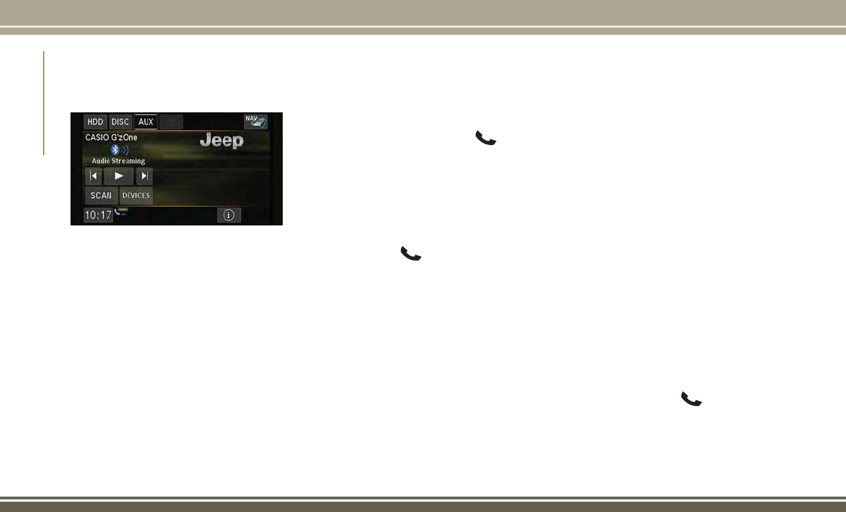
ers. Your connected device must be
Bluetooth-compatible, and paired with your
radio (see Uconnect Phone for pairing in-
structions).
Non-Touchscreen Radios: Push the “AUX”
button on the radio faceplate until “BT” or
“Audio Streaming” is displayed on the radio
screen.
Touchscreen-Radios: Push the RADIO/MEDIA
or MEDIA button on the faceplate and then
press the “AUX” button on the touchscreen.
UCONNECT PHONE
The Uconnect Phone is a voice-activated,
hands-free, in-vehicle communications sys-
tem with Voice Command Capability that al-
lows you to dial a phone number with your
mobile phone using simple voice commands
(see Voice Command section).
• To determine if your vehicle is equipped
with Uconnect Phone, push the
“Uconnect Phone” button
located
on the radio faceplate. If your vehicle has
this feature, you will hear a voice prompt.
If not, you will see a message on the radio
“Uconnect Phone not available.”
NOTE:
To access the tutorial, push the “Uconnect
Phone” button
. After the BEEP, say
“tutorial.” Push any button on the faceplate,
or press any button on the touchscreen, to
cancel the tutorial.
• Refer to “Uconnect Phone” in “Multime-
dia” in your Owner's Manual on
www.jeep.com/en/owners/manuals for fur-
ther details.
NOTE:
The Uconnect Phone requires a mobile
phone equipped with the Bluetooth Hands-
Free Profile, Version 1.0 or higher. For
Uconnect Customer Support: U.S. residents -
visit UconnectPhone.com or call
1-877-855-8400. Canadian residents - visit
UconnectPhone.com or call,
1-800-465-2001 (English) or
1-800-387-9983 (French). This site will
provide specific instructions based on the
type of mobile phone being paired.
Phone Pairing
NOTE:
Pairing is a one - time initial setup before
using the phone. Prior to starting the pairing
procedure ensure all additional phones
within the vehicle have their Bluetooth dis-
abled.
1. Activate Bluetooth on the mobile phone
you are pairing.
2. Push the “Phone”
button.
3. Wait for the “ready” prompt and BEEP.
4. After the BEEP, say ”setup” or “Uconnect
device setup.”
Bluetooth Streaming Audio
MULTIMEDIA
222

5. After the BEEP, say “device pairing.”
6. After the BEEP, say “pair a device.”
7. Follow the audible prompts.
• You will be asked to say a four-digit Per-
sonal Identification Number (PIN), which
you will later need to enter into your mo-
bile phone. You can say any four-digit PIN.
You will not need to remember this PIN
after the initial pairing process.
• You will then be prompted to give the
phone pairing a name (each phone paired
should have a unique name).
• Next you will be asked to give this new
pairing a priority of 1 through 7 (up to
seven phones may be paired); 1 is the
highest and 7 is the lowest priority. The
system will only connect to the highest
priority phone that exists within the prox-
imity of the vehicle.
• You will then need to start the pairing
procedure on your cell phone. Follow the
Bluetooth instructions in your cell phone
Owner's Manual to complete the phone
pairing setup.
Phonebook
Phonebook Download — Automatic Phonebook
Transfer From Mobile Phone
If equipped and specifically supported by
your phone, Uconnect Phone automatically
downloads names (text names) and number
entries from your mobile phone’s phonebook.
Specific Bluetooth Phones with Phone Book
Access Profile may support this feature. Au-
tomatic Transfer is indicated by a green arrow
at the bottom of the screen. See
UconnectPhone.com for supported phones.
• Automatic download and update, if sup-
ported, begins as soon as the Bluetooth
wireless phone connection is made to the
Uconnect Phone. For example, after you
start the vehicle.
NOTE:
The mobile phone may require authorization
prior to download.
• A maximum of 1,000 entries per phone
will be downloaded and updated every
time a phone is connected to the
Uconnect Phone.
Mobile Phone Pairing
Uconnect myPhone
223

• Depending on the maximum number of
entries downloaded, there may be a short
delay before the latest downloaded names
can be used. Until then, if available, the
previously downloaded phonebook is
available for use.
• Only the phonebook of the currently con-
nected mobile phone is accessible.
• Only the mobile phone’s phonebook is
downloaded. The SIM card phonebook is
not part of the Mobile phonebook.
• This downloaded phonebook cannot be
edited or deleted on the Uconnect Phone.
These can only be edited on the mobile
phone. The changes are transferred and
updated to Uconnect Phone on the next
phone connection.
Making A Phone Call
• Push the “Phone” button .
• After the BEEP, say “dial” (or “call” a
name).
• After the BEEP, say number (or name).
Receiving A Call — Accept (And End)
• When an incoming call rings/is announced
on Uconnect, push the “Phone” button
.
• To end a call, push the “Phone” button
.
Mute (Or Unmute) Microphone During
Call
• During a call, push the “Voice Command”
button
.
• After the BEEP, say “mute” (or “mute
off”).
Transfer Ongoing Call Between Handset
And Vehicle
• During a call, push the “Voice Command”
button
.
• After the BEEP, say “transfer call.”
Changing The Volume
• Start a dialogue by pushing the “Phone”
button
, then adjust the volume dur-
ing a normal call.
• Use the radio ON/OFF VOLUME rotary
knob to adjust the volume to a comfortable
level while the Uconnect system is speak-
ing. Please note the volume setting for
Uconnect is different than the audio
system.
WARNING!
• Any voice commanded system should be
used only in safe driving conditions fol-
lowing applicable laws regarding phone
use. Your attention should be focused on
safely operating the vehicle. Failure to
do so may result in a collision causing
you and others to be severely injured or
killed.
• In an emergency, to use Uconnect
Phone, your mobile phone must be:
• turned on
• paired to Uconnect Phone
• have network coverage
MULTIMEDIA
224

UCONNECT VOICE
COMMAND
Voice Command Operation
The Uconnect Voice Command system allows
you to control your AM, FM radio, satellite
radio, disc player, HDD, Uconnect Phone, a
memo recorder, and supported portable me-
dia devices.
• When you push the “Voice Command”
button
located on the radio face-
plate or steering wheel, you will hear a
beep. The beep is your signal to give a
command. If you do not say a command
within a few seconds, the system will pres-
ent you with a list of options. If you ever
want to interrupt the system while it lists
options, push the “Voice Command” but-
ton
, listen for the BEEP, and say
your command.
NOTE:
U.S. residents visit driveuconnect.com for
more info on which voice command features
apply to your vehicle. Canadian residents
visit driveuconnect.ca for more info on which
voice command features apply to your ve-
hicle.
• Start a dialogue by pushing the “Voice
Command” button
, you will hear a
beep. The beep is your signal to give a
command. Below are a list of voice com-
mands for each of the different modes:
While In: Voice Command Example:
Main Menu
“Radio AM” (to switch to the AM radio mode)
“Radio FM” (to switch to the FM radio mode)
“Satellite Radio” (to switch to the Satellite radio mode)
“Disc” (to switch to the disc mode)
“USB” (to switch to the USB mode)
“Bluetooth Streaming” (to switch to the Bluetooth Streaming mode)
“Memo” (to switch to the memo recorder)
“System Setup” (to switch to system setup)
225

While In: Voice Command Example:
Radio Mode
“Frequency” (to change the frequency)
“Next Station” (to select the next station)
“Previous Station” (to select the previous station)
“Radio Menu” (to switch to the radio menu)
“Main Menu” (to switch to the main menu)
SiriusXM Satellite Radio Mode
“Channel Number” (to change the channel by its spoken number)
“Next Channel” (to select the next channel)
“Previous Channel” (to select the previous channel)
“List Channel” (to hear a list of available channels)
"Channel Name" (to change the channel by its spoken name)
“Select Name” (to say the name of a channel)
“Radio Menu” (to switch to the radio menu)
“Main Menu” (to switch to the main menu)
Disc Mode
“Track” (#) (to change the track)
“Next Track” (to play the next track)
“Previous Track” (to play the previous track)
“Main Menu” (to switch to the main menu)
MULTIMEDIA
226

While In: Voice Command Example:
Memo Mode
To switch to the voice recorder mode, say “Memo.” The following are common voice commands for
this mode: “New Memo” (to record a new memo) — During the recording, you may push the Voice
Command button
to stop recording. You proceed by saying one of the following commands:
— “Save” (to save the memo)
— “Continue” (to continue recording)
— “Delete” (to delete the recording)
— “Play Memos” (to play previously recorded memos) — During the playback you may push the Voice
Command button
to stop playing memos. You proceed by saying one of the following com-
mands:
— “Repeat” (to repeat a memo)
— “Next” (to play the next memo)
— “Previous” (to play the previous memo)
— “Delete” (to delete a memo)
— “Delete All” (to delete all memos)
227
Voice Text Reply
If equipped with Uconnect Voice Command,
your Uconnect 430N radio may be able to
play incoming Short Message Service (SMS)
messages (text messages) through the vehi-
cle's sound system. It also allows you to
respond by selecting from various predefined
phrases.
NOTE:
Not all phones are compatible with this fea-
ture. Refer to the phone compatibility list at
UconnectPhone.com. Connected mobile
phones must be bluetooth-compatible and
paired with your radio.
• Push the “Voice Command” button
and after the BEEP, say “SMS” to get
started.
NOTE:
To access the tutorial, push the “Voice Com-
mand” button
. After the BEEP, say
“tutorial.” Push any button on the faceplate
or press any button on the touchscreen to
cancel the tutorial.
WARNING!
Any voice commanded system should be
used only in safe driving conditions follow-
WARNING!
ing applicable laws regarding phone use.
Your attention should be focused on safely
operating the vehicle. Failure to do so may
result in a collision causing you and others
to be severely injured or killed.
MULTIMEDIA
228

CUSTOMER ASSISTANCE
SUGGESTIONS FOR OBTAINING
SERVICE FOR YOUR VEHICLE . .230
Prepare For The Appointment.......230
Prepare A List ................230
Be Reasonable With Requests ......230
IF YOU NEED ASSISTANCE . . . .230
FCA US LLC Customer Center ......231
FCA Canada Inc. Customer Center . . . .231
In Mexico Contact ..............231
Puerto Rico And U.S. Virgin Islands . . .231
Customer Assistance For The Hearing Or
Speech Impaired (TDD/TTY)........231
Service Contract ..............231
WARRANTY INFORMATION . . .232
MOPARPARTS .............232
REPORTING SAFETY DEFECTS
. .232
In The 50 United States And
Washington, D.C. ..............232
In Canada...................233
PUBLICATION ORDER FORMS . .233
CUSTOMER ASSISTANCE
229

SUGGESTIONS FOR
OBTAINING SERVICE FOR
YOUR VEHICLE
Prepare For The Appointment
If you are having warranty work done, be sure
to have the right papers with you. Take your
warranty folder. All work to be performed may
not be covered by the warranty. Discuss ad-
ditional charges with the service manager.
Keep a maintenance log of your vehicle's
service history. This can often provide a clue
to the current problem.
Prepare A List
Make a written list of your vehicle's problems
or the specific work you want done. If you've
had an accident or work done that is not on
your maintenance log, let the service advisor
know.
Be Reasonable With Requests
If you list a number of items and you must
have your vehicle by the end of the day,
discuss the situation with the service advisor
and list the items in order of priority. At many
authorized dealers, you may obtain a rental
vehicle at a minimal daily charge. If you need
a rental, it is advisable to make these ar-
rangements when you call for an appoint-
ment.
IF YOU NEED ASSISTANCE
The manufacturer and its authorized dealer
are vitally interested in your satisfaction. We
want you to be happy with our products and
services.
Warranty service must be done by an autho-
rized dealer. We strongly recommend that you
take the vehicle to an authorized dealer. They
know your vehicle the best, and are most
concerned that you get prompt and high
quality service. The manufacturer's autho-
rized dealer have the facilities, factory-
trained technicians, special tools, and the
latest information to ensure the vehicle is
fixed correctly and in a timely manner.
This is why you should always talk to an
authorized dealer service manager first. Most
matters can be resolved with this process.
• If for some reason you are still not satis-
fied, talk to the general manager or owner
of the authorized dealer. They want to know
if you need assistance.
• If an authorized dealer is unable to resolve
the concern, you may contact the manu-
facturer's customer center.
Any communication to the manufacturer's
customer center should include the following
information:
• Owner's name and address
• Owner's telephone number (home and of-
fice)
• Authorized dealer name
• Vehicle Identification Number (VIN)
• Vehicle delivery date and mileage
CUSTOMER ASSISTANCE
230

FCA US LLC Customer Center
P.O. Box 21–8004
Auburn Hills, MI 48321–8004
Phone: (800) 247-9753
FCA Canada Inc. Customer Center
P.O. Box 1621
Windsor, Ontario N9A 4H6
Phone: (800) 465-2001 English / (800)
387-9983 French
In Mexico Contact
Av. Prolongacion Paseo de la Reforma, 1240
Sante Fe C.P. 05109
Mexico, D. F.
In Mexico City: 5081-7568
Outside Mexico City: 1-800-505-1300
Puerto Rico And U.S. Virgin Islands
Customer Service Chrysler International Ser-
vices LLC
P.O. Box 191857
San Juan 00919-1857
Tel.: (787) 782-5757
Fax: (787) 782-3345
Customer Assistance For The Hearing Or
Speech Impaired (TDD/TTY)
To assist customers who have hearing diffi-
culties, the manufacturer has installed spe-
cial TDD (Telecommunication Devices for the
Deaf) equipment at its customer center. Any
hearing or speech impaired customer, who
has access to a TDD or a conventional tele-
typewriter (TTY) in the United States, can
communicate with the manufacturer by dial-
ing 1-800-380-CHRY.
Canadian residents with hearing difficulties
that require assistance can use the special
needs relay service offered by Bell Canada.
For TTY teletypewriter users, dial 711 and for
Voice callers, dial 1-800-855-0511 to con-
nect with a Bell Relay Service operator.
Service Contract
You may have purchased a service contract
for a vehicle to help protect you from the high
cost of unexpected repairs after the manufac-
turer's New Vehicle Limited Warranty expires.
The manufacturer stands behind only the
manufacturer's service contracts. If you pur-
chased a manufacturer's service contract,
you will receive Plan Provisions and an Owner
Identification Card in the mail within three
weeks of the vehicle delivery date. If you have
any questions about the service contract, call
the manufacturer's Service Contract National
Customer Hotline at 1-800-521-9922 (Ca-
nadian residents, call (800) 465-2001 Eng-
lish / (800) 387-9983 French).
The manufacturer will not stand behind any
service contract that is not the manufactur-
er's service contract. It is not responsible for
any service contract other than the manufac-
turer's service contract. If you purchased a
service contract that is not a manufacturer's
231

service contract, and you require service after
the manufacturer's New Vehicle Limited War-
ranty expires, please refer to the contract
documents, and contact the person listed in
those documents.
We appreciate that you have made a major
investment when you purchased the vehicle.
An authorized dealer has also made a major
investment in facilities, tools, and training to
assure that you are absolutely delighted with
the ownership experience. You will be
pleased with their sincere efforts to resolve
any warranty issues or related concerns.
WARNING!
Engine exhaust (internal combustion en-
gines only), some of its constituents, and
certain vehicle components contain, or
emit, chemicals known to the State of
California to cause cancer and birth de-
fects, or other reproductive harm. In addi-
tion, certain fluids contained in vehicles
and certain products of component wear
contain, or emit, chemicals known to the
WARNING!
State of California to cause cancer and
birth defects, or other reproductive harm.
WARRANTY INFORMATION
See the Warranty Information Booklet, lo-
cated in the owner’s information kit, for the
terms and provisions of FCA US LLC warran-
ties applicable to this vehicle and market.
MOPAR PARTS
MOPAR fluids, lubricants, parts, and acces-
sories are available from an authorized
dealer. They are recommended for your ve-
hicle in order to help keep the vehicle oper-
ating at its best.
REPORTING SAFETY
DEFECTS
In The 50 United States And Washington,
D.C.
If you believe that your vehicle has a
defect that could cause a crash or
cause injury or death, you should im-
mediately inform the National High-
way Traffic Safety Administration
(NHTSA) in addition to notifying FCA
US LLC.
If NHTSA receives similar complaints,
it may open an investigation, and if it
finds that a safety defect exists in a
group of vehicles, it may order a recall
and remedy campaign. However,
NHTSA cannot become involved in in-
dividual problems between you, your
authorized dealer or FCA US LLC.
CUSTOMER ASSISTANCE
232

To contact NHTSA, you may call the
Vehicle Safety Hotline toll free at
1-888-327-4236 (TTY:
1-800-424-9153); or go to http://
www.safercar.gov
; or write to: Administra-
tor, NHTSA, 1200 New Jersey Avenue, SE.,
West Building, Washington, D.C. 20590. You
can also obtain other information about mo-
tor vehicle safety from http://
www.safercar.gov.
In Canada
If you believe that your vehicle has a
safety defect, you should contact the
Customer Service Department imme-
diately. Canadian customers who wish
to report a safety defect to the Cana-
dian government should contact
Transport Canada, Motor Vehicle De-
fect Investigations and Recalls at
1-800-333-0510 or go to http://
www.tc.gc.ca/roadsafety/
.
PUBLICATION ORDER
FORMS
• If you are the first registered retail owner
of your vehicle, you may obtain a compli-
mentary printed copy of the Owner's
Manual, Navigation/Uconnect Manuals or
Warranty Booklet. United States custom-
ers may visit the Jeep Contact Us page at
www.jeep.com Scroll to the bottom of the
page and select the “Contact Us” link,
then select the “Owner’s Manual and
Glove Compartment Material” from the
left menu. You may also obtain a compli-
mentary copy by calling 1-877-426-5337
(U.S.) or 1-800-387-1143 (Canada).
• Replacement User Guide kits or, if you
prefer, additional printed copies of the
Owner's Manual, Warranty Booklet or Ra-
dio Manuals may be purchased by visiting
www.techauthority.com or by calling
1-800-890-4038 (U.S.) or
1-800-387-1143 (Canada). Visa, Master
Card, American Express and Discover or-
ders are accepted. If you prefer mailing
your order, please call the above numbers
for an order form.
NOTE:
• A street address is required when ordering
manuals (no P.O. Boxes).
• The Owner's Manual and User Guide elec-
tronic files are also available on the
Chrysler, Jeep, Ram Truck, Dodge and SRT
websites.
• Click on the “For Owners” tab, select
“Owner/Service Manuals”, then select
your desired model year and vehicle from
the drop down lists.
233

234

Adding Fuel .................133
Adding Washer Fluid ............172
Additives, Fuel................194
Adjust
Down ....................20
Forward ...................20
Rearward ..................20
Up......................20
AirBag.....................96
Air Bag Operation .............98
Air Bag Warning Light ..........95
Enhanced Accident Response
. .102, 164
Event Data Recorder (EDR) ......164
If A Deployment Occurs ........102
Knee Impact Bolsters ..........98
Maintaining Your Air Bag System . .103
Side Air Bags ...............98
Transporting Pets ............115
Air Bag Light............55, 95, 116
Air Bag Maintenance ............103
Air Conditioner Maintenance .......177
Air Conditioning ................31
Air Conditioning Controls ..........31
Air Conditioning Filter.........40, 177
Air Conditioning, Operating Tips . . .40, 41
Air Conditioning Refrigerant........177
Air Conditioning System .....31, 38, 177
Alarm (Security Alarm)............56
Alarm System (Security Alarm) .......15
Antifreeze (Engine Coolant) ........194
Capacities ................194
Anti-Lock Brake System (ABS) .......70
Anti-Lock Warning Light ...........59
Assist, Hill Start................72
Audio Jack ...........201, 205, 209
Audio Settings ............201, 203
Automatic Dimming Mirror .........25
Automatic Door Locks ............17
Automatic Temperature Control (ATC) . . .38
Automatic Transaxle .............13
Fluid Level Check ...........176
Automatic Transmission ......124, 126,
175, 176
Fluid And Filter Changes . . . .175, 177
Fluid Level Check ...........175
Fluid Type .........175, 176, 196
Special Additives ........175, 176
Autostick................126, 128
Axle Fluid...................196
Battery .....................56
Charging System Light .........56
Belts, Seat ..................116
B-Pillar Location ..............182
Brake Assist System .............71
Brake Fluid ..................196
Brake,
Parking ...............
.122
Brakes.....................192
Brake System .............173, 192
Master Cylinder .............173
Parking ..................122
Warning Light ...............55
Brake/Transmission Interlock .......126
Bulb Replacement .............140
Bulbs, Light ..............118, 140
Camera, Rear ................131
Capacities, Antifreeze (Engine Coolant)
. .194
Capacities, Fluid ..............194
Caps, Filler
Fuel ....................133
Oil (Engine) ...........170, 171
Carbon Monoxide Warning .........115
Cargo Area Cover ...............47
Cargo Area Features .............47
INDEX
235

Cargo Compartment .............47
Light ....................47
Cargo Light...................47
Cargo Load Floor ...............47
Cargo Tie-Downs................47
Car Washes ..................188
CD (Compact Disc) Player .....201, 204
Center High Mounted Stop Light .....141
Certification Label .............134
Chains, Tire..................186
Changing A Flat Tire .........144, 179
Check Engine Light (Malfunction Indicator
Light) ....................67
Checking Your Vehicle For Safety . . . .115
Checks, Safety ................115
Child Restraint................104
Child Restraints
Booster Seats ..............106
Child Restraints .............104
Child Seat Installation .........113
How To Stow An Unused ALR Seat
Belt ....................111
Infants And Child Restraints .....105
Lower Anchors And Tethers For
Children .................108
Older Children And Child Restraints
. .106
Seating Positions ............107
Child Safety Locks ..............17
Cleaning
Wheels ..................185
Climate Control ................31
Clock Setting..........201, 203, 207
Clutch .....................173
Clutch Fluid .................173
Cold Weather Operation ..........121
Compass ....................61
Connector
UCI ....................221
Universal Consumer Interface
(UCI) ...................221
Contract, Service ..............231
Coolant (Antifreeze).............194
Cooling System ...............172
Coolant Level ..............172
Selection Of Coolant (Antifreeze) . .195
Customer Assistance ............230
Dealer Service ................178
Defroster, Windshield............116
Delay (Intermittent) Wipers .........29
Diagnostic System, Onboard ........66
Dimmer Switch, Headlight .........27
Door Locks
Child-Protection Door Lock — Rear
Doors ....................17
Door Locks .................16
KeyFob...................16
Remote ...................16
Remote Keyless Entry ..........16
Door Locks, Automatic ............17
Downshifting .................124
Driver's Seat Back Tilt ............19
Electric Remote Mirrors ...........26
Electronic Brake Control System ......71
Anti-Lock Brake System ........70
Electronic Roll Mitigation .......76
Traction Control System ........73
Electronic Speed Control (Cruise
Control) ..................129
Electronic Stability Control (ESC) .....73
Electronic Throttle Control Warning
Light .....................57
Emergency, In Case Of
Jacking ..............144, 179
Jump Starting ..............157
T
owing .................
.163
INDEX
236

Emission Control System Maintenance . .67
Engine .................170, 171
Break-In Recommendations .....121
Checking Oil Level ...........172
Coolant (Antifreeze) .......172, 195
Cooling ..................172
Exhaust Gas Caution ..........115
Jump Starting ..............157
Oil .................194, 195
Oil Filler Cap ...........170, 171
Overheating ...............160
Enhanced Accident Response
Feature ...............102, 164
Exhaust Gas Caution ............115
Exhaust System ...............115
Exterior Lights .............26, 118
Filters
Air Conditioning ..........40, 177
Engine Oil ................195
Flashers
Hazard Warning .............140
Turn Signal .........60, 118, 141
Flooded Engine Starting ..........121
Fluid, Brake .................196
Fluid Capacities ...............194
Fluid Leaks ..................118
Fluid Level Checks
Automatic Transaxle ..........176
Automatic Transmission ........175
Cooling System .............172
Fog Lights ................27, 141
Folding Rear Seat ...............21
Four-Way Hazard Flasher..........140
Four Wheel Drive ..............129
Systems .................129
Four Wheel Drive Operation ........129
Freeing A Stuck Vehicle ..........161
Fuel ......................193
Adding ..................133
Additives .................194
Capacity .................194
Filler
Cap
(Gas Cap) ..........133
Gasoline .................193
Light ....................59
Materials Added ............194
Octane Rating ..........193, 195
Tank Capacity ..............194
Fueling ....................133
Garage Door Opener (HomeLink) . . .48, 50
Gas Cap (Fuel Filler Cap) .......67, 133
Gasoline (Fuel) ............193, 194
Gear Select Lever Override ........161
GPS Navigation (Uconnect GPS) .....214
GVWR .....................134
Hazard Warning Flasher ..........140
Headlights ..................141
High Beam/Low Beam Select
Switch ...................27
On With Wipers ...........28, 30
Passing ..................27
Replacing ................141
Switch ...................26
Head Restraints ................22
Heated Mirrors.................26
Heated Seats..................20
Heater......................31
High Beam/Low Beam Select (Dimmer)
Switch ....................27
Hill Descent Control .............77
Hill Start Assist ................72
HomeLink
Operation ..................50
HomeLink (Garage Door Opener) . . .48, 50
Hood Release .................45
Ignition .....................13
Key .....................13
Ignition Key Removal.............13
237

Inside Rearview Mirror ............25
Instrument Cluster ..............60
Instrument Panel Lens Cleaning .....189
Integrated Power Module (Fuses) . . . .142
Interior And Instrument Lights .......28
Interior Appearance Care .........189
Interior Lights .................28
Intermittent Wipers (Delay Wipers) ....29
Introduction ...................1
Inverter Outlet (115V) ............52
Inverter, Power ................52
iPod/USB/MP3 Control
Bluetooth Streaming Audio ......221
Jacking Instructions ............146
Jack Location ................145
Jack Operation .........144, 146, 179
Jump Starting ................157
Key-In Reminder ...............14
Keys .......................13
Lane Change And Turn Signals ......141
Lane Change Assist..............27
Lap/Shoulder Belts ..............86
Latches ....................118
Hood ....................45
Leaks, Fluid .................118
Liftgate Window Wiper/Washer .......31
Light Bulbs ..............118, 140
Lights .....................118
AirBag .............55, 95, 116
Back-Up .................141
Brake Assist Warning ..........75
Brake Warning ..............55
Cargo ....................47
Center Mounted Stop .........141
Cruise ...................61
Daytime Running ............26
Dimmer Switch, Headlight .......27
Exterior ..................118
Fog .................27, 141
Hazard Warning Flasher ........140
Headlights .................26
Headlights On With Wipers . . . .28, 30
Headlight Switch .............26
High Beam ................
2
7
High Beam/Low Beam Select .....27
Instrument Cluster ............26
Interior ...................28
License ..................141
Lights On Reminder ...........28
Low Fuel ..................59
Malfunction Indicator (Check Engine)
.57
Map Reading ...............28
Park ....................60
Seat Belt Reminder ...........55
Security Alarm ...........15, 56
Tire Pressure Monitoring (TPMS) . . .57
Traction Control .............75
Turn Signal .......27, 60, 118, 141
Warning (Instrument Cluster
Description) ................60
Loading Vehicle ...............134
Tires ...................182
Locks ......................16
Automatic Door ..............17
Child Protection .............17
Door ....................16
Power Door ................17
Lug Nuts ...................193
Lumbar Support................19
Maintenance Schedule ...........166
Malfunction Indicator Light (Check
Engine) .................57, 67
Manual, Service ...............233
Manual Transmission ............174
Fluid Level Check ...........174
Frequency Of Fluid Change .....174
Lubricant Selection .......174, 196
INDEX
238

Map/Reading Lights .............28
Master Cylinder (Brakes) ..........173
Media Center Radio.............206
Mini-Trip Computer ..............61
Mirrors .....................25
Automatic Dimming ...........25
Electric Powered .............26
Heated ...................26
Rearview ..................25
Monitor, Tire Pressure System .......77
MOPAR Accessories.............196
MOPAR Parts.................232
Navigation ..................212
Navigation System (Uconnect GPS) . . .213
Navigation Voice Prompt Volume .....212
New Vehicle Break-In Period .......121
Occupant Restraints .............83
Octane Rating, Gasoline (Fuel) ......193
Oil, Engine...............194, 195
Capacity .................194
Checking .................172
Filter ...................195
Pressure Warning Light .........56
Recommendation ............194
Oil Pressure Light ...............56
Onboard Diagnostic System .........66
Operating Precautions ............66
Outlet
Power ...................50
Overheating, Engine ............160
Owner's Manual (Operator Manual) . . .233
Parking Brake ................122
Passing Light .................27
Personal Settings ...............65
Pets ......................115
Phone (Uconnect) ..............222
Placard, Tire And Loading Information .182
Power
Door Locks ................17
Inverter ..................52
Mirrors ...................26
Outlet (Auxiliary Electrical Outlet) . .50
Sunroof ..................43
Windows ..................42
Power Seats
Down ....................20
Forward ...................20
Rearward ..................
2
0
Tilt......................20
Up ......................20
Power Steering Fluid ............196
Power Transfer Unit .............196
Pregnant Women And Seat Belts......91
Preparation For Jacking ..........146
Pretensioners
Seat Belts .................92
Programmable Electronic Features ....65
Radio
Presets ...........201, 203, 208
Radio 130
Operating Instructions Radio
Mode ...................200
Radio 130 With Satellite Radio
Operating Instructions Radio
Mode ...................202
Radio Operation ...........201, 203
Rear Camera .................131
Rear Seat, Folding ..............21
Rearview Mirrors ...............25
Rear Wiper/Washer ..............31
Recreational Towing.............137
Refrigerant ..................177
Reminder, Seat Belt .............85
Remote Control
Security Alarm ..............15
Remote Sound System (Radio)
Controls ..................219
239

Remote Starting System ...........15
Replacement Bulbs .............140
Reporting Safety Defects .........232
Restraint, Head ................22
Restraints, Child ..............104
Retractable Cargo Area Cover ........47
Roll Over Warning ...............2
Rotation, Tires ................186
Safety Checks Inside Vehicle .......116
Safety Checks Outside Vehicle ......117
Safety Defects, Reporting .........232
Safety, Exhaust Gas.............115
Safety Information, Tire ..........179
Safety Tips ..................115
Satellite Radio (Uconnect Studios) . . .204
Schedule, Maintenance ..........166
Seat Belt
Adjustable Upper Shoulder Belt
Anchorage .................88
Automatic Locking Retractor (ALR) . .92
Energy Management Feature ......92
Lap/Shoulder Belt Operation ......87
Lap/Shoulder Belts ............86
Lap/Shoulder Belt Untwisting .....88
Pregnant Women .............91
Seat Belt Extender ............91
Seat Belt Pretensioner .........92
Seat Belt Reminder ...........85
Seat Belt Maintenance ...........189
Seat Belt Reminder..............85
Seat Belts ................84, 116
Adjustable Shoulder Belt ........88
Adjustable Upper Shoulder
Anchorage .................88
Child Restraint .............104
Extender ..................91
Front Seat ............84, 86, 87
Inspection ................116
Operating Instructions .........87
Pregnant Women .............91
Pretensioners ...............92
Rear Seat .................86
Reminder .................55
Untwisting Procedure ..........88
Seats ....................18, 20
Adjustment .............18, 20
Heated ...................
2
0
Lumbar Support .............19
Rear Folding ...............21
Seatback Release ............19
Tilting ...................19
Security Alarm ..............15, 56
Selection Of Coolant (Antifreeze).....195
Service Assistance .............230
Service Contract ...............231
Service Manuals ...............233
Settings, Personal ..............65
Shift Lever Override.............161
Shift Speeds, Manual Transmission . . .124
Shoulder Belts.................86
Signals, Turn ...........60, 118, 141
SIRIUS Travel Link .............214
Snow Chains (Tire Chains) .........186
Spare Tire...................145
Spark Plugs .................195
Speed Control
Accel/Decel ...............131
Cancel ..................130
Resume .................130
Speed Control (Cruise Control) ......129
Starting ....................120
Automatic Transmission ........120
Cold Weather ..............121
Engine Fails To Start .........121
Manual Transmission .........120
Remote ..................15
Starting Procedures.............120
Steering.....................24
Tilt Column ................24
Steering Wheel Audio Controls ......219
INDEX
240

Steering Wheel Mounted Sound System
Controls ..................219
Storage ....................188
Storage, Vehicle ................40
Stuck, Freeing ................161
Sunroof
Closing ...................44
Opening ...................44
Sun Roof ....................43
Supplemental Restraint System -
AirBag....................96
System, Remote Starting ..........15
Taillights ...................141
Temperature Control, Automatic (ATC) . .38
Tie Down Hooks, Cargo............47
Tilt
Down ....................20
Up ......................20
Tilt Steering Column .............24
Tire And Loading Information Placard . .182
Tire Markings.................179
Tires...................117, 186
Chains ..................186
Changing .............144, 179
Jacking ..............144, 179
Load Capacity ..............182
Pressure Monitor System (TPMS) . . .77
Pressure Warning Light .........57
Quality Grading .............186
Rotation .................186
Safety ..................179
Spare Tire ................145
Tire Safety Information ...........179
Tire Service Kit ........152, 153, 154,
155, 156, 157
Touchscreen Radio
Cleaning Your Touchscreen Radio . .212
Towing .....................136
Disabled Vehicle ............163
Guide ...................136
Recreational ...............137
Weight ..................136
Towing Vehicle Behind A Motorhome . .137
Traction Control ................73
Trailer Towing ................136
Trailer Towing Guide ............136
Trailer Weight ................136
T
ransaxle
Automatic .................
13
Transmission
Automatic ......124, 126, 175, 176
Fluid ............175, 176, 196
Transporting Pets ..............115
Trip Computer .................61
Turn Signals ............27, 60, 141
UCI Connector ................221
Uconnect Voice Command.........225
Uniform Tire Quality Grades ........186
Universal Consumer Interface (UCI)
Connector .................221
Untwisting Procedure, Seat Belt ......88
Vehicle Identification Number (VIN) . . .192
Vehicle Loading............134, 182
Vehicle Security Alarm (Security Alarm)
. .15
Vehicle Storage .............40, 188
Voice Command ...............225
Voice Prompt Volume
Navigation ................212
Volume
Navigation Voice Prompt ........212
Warning, Roll Over ...............2
Warranty Information ............232
Washer
Adding Fluid ..............172
Washers, Windshield .............30
Washing Vehicle ...............188
Wheel And Wheel Trim ...........185
241

Wheel And Wheel Trim Care........185
Wind Buffeting ................44
Window Fogging ................40
Windows ....................42
Power ...................42
Windshield Defroster ............116
Windshield Washers ...........29, 30
Windshield Wiper Blades .........178
Windshield Wipers ..............29
Wiper Blade Replacement .........178
Wipers, Intermittent .............29
INDEX
242

NOTES
243

NOTES
244

NOTES
245

NOTES
246

NOTES
247

NOTES
248

If you are the first registered retail
owner of your vehicle, you may
obtain a complimentary printed copy
of the Owner’s Manual, Navigation/
Uconnect Manuals or Warranty
Booklets by calling 1 877 426-5337
(U.S.) or 1 800 387-1143 (Canada)
or by contacting your dealer.
The driver’s primary responsibility is
the safe operation of the vehicle.
Driving while distracted can result in
loss of vehicle control, resulting in a
collision and personal injury. FCA US
LLC strongly recommends that the
driver use extreme caution when
using any device or feature that may
take their attention o the road.
Use of any electrical devices, such
as cellular telephones, computers,
portable radios, vehicle navigation
or other devices, by the driver
while the vehicle is moving is
dangerous and could lead to a
serious collision. Texting while
driving is also dangerous and
should never be done while the
vehicle is moving.
If you find yourself unable to
devote your full attention to vehicle
operation, pull o the road to a
safe location and stop your vehicle.
Some states or provinces prohibit
the use of cellular telephones or
texting while driving. It is always
the driver’s responsibility to comply
with all local laws.
Important:
This User Guide is intended to familiarize you with the
important features of your vehicle. Your Owner’s Manual,
Navigation/Uconnect Manuals and Warranty Booklets can be
found on your DVD (if applicable) or by visiting the website
on the back cover of your User Guide. We hope you find it
useful. U.S. residents can purchase replacement DVD kits by
visiting www.techauthority.com and Canadian residents can
purchase replacement DVD kits by calling 1 800 387-1143.
This guide has been prepared to help you
get quickly acquainted with your new Jeep
brand vehicle and to provide a convenient
reference source for common questions.
However, it is not a substitute for your
Owner’s Manual.
For complete operational instructions,
maintenance procedures and important
safety messages, please consult your
Owner’s Manual, Navigation/Uconnect
manuals found on the website on the back
cover and other Warning Labels
in your vehicle.
Not all features shown in this guide
may apply to your vehicle. For additional
information on accessories to help
personalize your vehicle, visit
www.mopar.com (U.S.), www.mopar.ca
(Canada) or your local Jeep brand dealer.
Driving and Alcohol:
Drunken driving is one of the most frequent causes of collisions. Your
driving ability can be seriously impaired with blood alcohol levels far below
the legal minimum. If you are drinking, don’t drive. Ride with a designated
non-drinking driver, call a cab, a friend, or use public transportation.
WARNING!
Driving after drinking can lead to a collision. Your perceptions are less
sharp, your reflexes are slower, and your judgment is impaired when you
have been drinking. Never drink and then drive.
2667646_17c_Patriot_UG_082616.indd 2 8/26/16 2:07 PM

2017 PATRIOT USER GUIDE
Jeep.com (U.S.) Jeep.ca (Canada)
DOWNLOAD A FREE ELECTRONIC COPY of the
Owner’s Manual and Warranty Booklet by visiting:
www.jeep.com/en/owners/manuals or
www.jeep.com/en/warranty (U.S.);
www.owners.mopar.ca/en (Canada).
©2016 FCA US LLC. All Rights Reserved.
Jeep is a registered trademark of FCA US LLC.
Whether it’s providing
information about specific
product features, taking a
tour through your vehicle’s
heritage, knowing what
steps to take following an accident,
or scheduling your next appointment,
we know you’ll find the app an
important extension of your Jeep
brand vehicle. Simply download the
app, select your make and model and
enjoy the ride. To get this app, go
directly to the App Store or Google
Play and enter the search keyword
“JEEP” (U.S. market only).
jeep.com /en /owners provides
special oers tailored to your
needs, customized vehicle galleries,
personalized service records and
more. To get this information, just
create an account and check
back often.
17MK74-926-AA
Patriot
Third Edition
User Guide
2667646_17c_Patriot_UG_082616.indd 1 8/26/16 2:07 PM
