
1
Owner’s Manual
English
Your new spa’s GFCI will trip.
A Ground Fault Interrupter (GFCI) Trip Test must occur to
allow proper spa function.
Spas that come with MXBP20 and MXBP501 control sys-
tems come with special instructions for the installer/
electrician. If they have not already advised you on what
to do or expect from the GFCI Trip Test, please contact
them for instructions.
If the GFCI breaker connected to your spa trips, this is
normal behavior. Please reset the breaker and enjoy
your spa. The trip test has been completed successfully.
If your spa was not wired to a GFCI breaker or your
breaker fails the GFCI Trip Test, the spa will repeatedly
attempt (at preset intervals) to trip the breaker in the fu-
ture until such time that it triggers a GFCI Trip. If a GFCI
does not trip properly, your spa’s display will show an
error message.
GFCI breakers are important safety devices required by
code for your hot tub. For more information, refer to the
MXBP20 and MXBP501 sections of this manual or your
local dealer.
ALERT

2
Owner’s Manual
English
WARNING:
Children should not use spas or hot tubs
without adult supervision.
WARNING:
Do not use spas or hot tubs unless all suction
guards are installed to prevent body and hair
entrapment.
WARNING:
Pregnant, or possibly pregnant, women should
consult a physician before using a spa or hot tub.
WARNING:
People with infectious diseases should not
use a spa or hot tub.
WARNING:
To avoid injury, exercise care when entering
or exiting the spa or hot tub.
WARNING:
Do not use drugs or alcohol before or during
the use of a spa or hot tub to avoid
unconsciousness and possible drowning.
WARNING:
People using medications and/or having an
adverse medical history should consult a
physician before using a spa or hot tub.
WARNING:
Water temperature in excess of 100°F (38°C)
may be injurious to your health.
WARNING:
Before entering the spa or hot tub, measure
the water temperature with an accurate
thermometer.
WARNING:
Do not use a spa or hot tub immediately
following strenuous exercise.
WARNING:
Prolonged immersion in a spa or hot tub may
be injurious to your health.
WARNING:
Maintain water chemistry in accordance with
manufacturer’s instruction.
WARNING:
Do not permit electric appliances (such as a
light, telephone, radio or television) within
5 feet (1.5m) of the spa or hot tub.
WARNING:
The use of alcohol or drugs can greatly
increase the risk of fatal hyperthermia in hot
tubs and spas.
IMPORTANT SAFETY WARNINGS
SAVE THESE INSTRUCTIONS

3
Owner’s Manual
English
TABLE OF CONTENTS
GFCI Alert.............................................................1
Important Safety Warnings...............................2
Table of Contents................................................3
Important Safety Instructions.........................6
Dos and Don’ts........................................................8
Hyperthermia...........................................................8
Spa Installation....................................................9
European Spas........................................................9
Site and Positioning...............................................9
Outdoor Installation..............................................9
Indoor Installation..................................................9
Thermal Creep.......................................................10
Spa System Components................................11
Spa Components..............................................12
Jets and Air Controls........................................13
Jets (Directional, Rotating, Euro)....................13
Cleaning or Replacing Jets...............................13
Cleaning the Jets.................................................13
Air Controls.............................................................14
Electrical Information......................................15
Important Safety Instructions.........................15
Ground-Fault Circuit Interruptor....................15
Residual Current Device....................................15
Installation Options.............................................15
Voltage/Amperage Charts..............................17
Start Up Procedures.........................................23
Priming Your Spa.................................................23
Smart Touch Water Proof Control Panel...... 24
Main Screen...........................................................24
Set Temperature...................................................25
Spa Screen..............................................................25
Common Buttons................................................26
Settings Screen.....................................................28
Programming.........................................................28
Modes of Operation............................................29
Filling It UP..............................................................30
Priming Operations.............................................31
Spa Behavior..........................................................31
Pumps......................................................................31
Filtration and OZone...........................................32
Freeze Protection.................................................32
Adjusting Filtration..............................................33
Additional Settings..............................................34
Restricting Operation.........................................34
Unlocking................................................................35
Scenes......................................................................35
Additional Settings..............................................36
Information............................................................37
System Information.............................................37
GFCI Test Feature..................................................38
General Messages................................................39
Reminder Messages............................................40
300 Control Panel.............................................41
Operating Instructions.......................................41
User’s Pads.............................................................41
Temperature Controls........................................42
Modes of Operation............................................42
Setting the Time...................................................43
Preset Filter Cycles...............................................43
Changing Filter Cycles........................................43
Light..........................................................................43

4
Owner’s Manual
English
501 Control Panel.............................................44
Operating Instructions...........................................44
User’s Pads.............................................................45
Temperature Controls........................................45
Jets............................................................................46
Modes of Operation............................................46
Preset Filter Cycles...............................................46
Changing Filter Cycles........................................47
504 Control Panel.............................................48
Operating Instructions...........................................48
User’s Pads.............................................................49
Temperature Controls........................................49
Jets............................................................................49
Light..........................................................................50
Modes of Operation............................................50
Setting Filtration Cycles.....................................50
Preset Filter Cycles...............................................50
Changing Filter Cycles........................................51
Clean Up Cycle......................................................51
Bluetooth/MP3 Audio System Option.........51
TP600 Control Panel.........................................53
Main Menus........................................................... 53
Filling Your Spa.....................................................54
Spa Behavior..........................................................54
Temperature and Temp Range........................55
Mode - Rest and Ready......................................56
Show and Set Time-of-Day...............................56
Flip (Invert Display)..............................................56
Restric ting Operation........................................57
Unlocking................................................................57
Adjusting Filtration..............................................57
Wi-Fi Connectivity................................................57
GFCI Trip Test.........................................................57
TP800 Control Panel.........................................58
Button Functions..................................................58
The Main Screen...................................................59
Spa & Shortcut Screens......................................59
The Settings Screen.............................................60
Filling Your Spa.....................................................61
Spa Behavior..........................................................62
Time-of-Day............................................................62
Adjusting Filtration..............................................63
Restricting Operation.........................................63
Unlocking................................................................63
Wi-Fi Connectivity................................................63
Scenes......................................................................63
Color and Language...........................................63
GFCI Test Feature..................................................64
Auxiliary Panel.......................................................64
Therapy Sequencer..............................................64
Bluetooth Connection.....................................67
WiFi Connectivity..............................................68
Smart Device WiFi Spa Controls.....................68
Getting Started.....................................................68
After Application Download............................68
Connect to your Spa...........................................69
Connecting to WiFi Network...........................69
Application Functions........................................70
Settings........................................................................70
Setting Time..........................................................70
Setting Filter Cycles.............................................71
Controls...................................................................71
Equipment Safety Features............................72
Automatic Time Outs.........................................72
Common LCD Equipment Messages............72
Common LCD Messages....................................73

5
Owner’s Manual
English
Maintenance......................................................74
Water Chemistry...................................................74
Sanitizing.................................................................74
pH Level...................................................................74
Water Maintenance.............................................74
Sanitizing With Ozone........................................75
Specialty Chemicals............................................75
Draining Your Spa................................................75
Filter Maintenance...............................................76
Winterizing.............................................................76
Spa Cabinet Care.................................................77
Spa Surface Care and Cleaning.......................77
Light Bulbs..............................................................77
Common Water Problems...............................78
Common Hardware Problems........................81
Spa Soaking Guidelines..................................83
Safety sign.........................................................84
Limited Warranty Summary............................84
Copyrights and Trademarks...........................85
Notes...................................................................86

6
Owner’s Manual
English
IMPORTANT SAFETY INSTRUCTIONS
1. WARNING - To reduce the risk of injury,
do not allow children to use spa unless
they are closely supervised at all times.
2. A wire connector is provided on this unit
to connect a minimum 6 AWG (5.15 mm
2
)
solid copper conductor between this unit
and any metal equipment, metal enclosu-
res of electrical equipment, metal water
pipe or conduit within 5 feet (1.5m) of
the unit.
3. (For cord-connected/convertible units)
DANGER - Risk of injury.
a. Replace damaged cord immediately.
b. Do not bury cord.
c. Connect to a grounded, grounding
type receptacle only.
4. DANGER - Risk of Accidental Drowning.
Extreme caution must be exercised
to prevent unauthorized access by
children. To avoid accidents, ensure that
children cannot use this spa unless they
are supervised at all times.
5. DANGER - Risk of injury. The suction
ttings in this spa are sized to match the
specic water ow created by the pump.
If you must replace the suction ttings
or the pump, be sure the ow rates are
compatible. Never operate spa if the
suction ttings are broken or missing.
Never replace a suction tting with
one rated less than the ow rate marked
on the original suction tting.
6. DANGER - Risk of Electric Shock. Install
at least 5 feet (1.5m) from all metal
surfaces. As an alternative, a spa may be
installed within 5 feet (1.5m) of metal
surfaces if each metal surface is
permanently connected by a minimum
6 AWG (5.15 mm
2
) solid copper
conductor to the wire connector on the
terminal box that is provided for
this purpose.
7. DANGER - Risk of Electric Shock. Do not
permit any electric appliance (such as a
light, telephone, radio or television)
within 5 feet (1.5m) of the spa.
8. WARNING - To reduce the risk of injury:
a. The water in a spa should never
exceed 104°F (40°C).. Temperatures be
tween 100°F (38°C) and 104°F (40°C)
are considered safe for a healthy adult.
Lower temperatures are recommended
for young children and when spa use
exceeds 10 minutes.
b. Since excessive water temperatures
have a high potential for causing fetal
damage during the early months of preg-
nancy, pregnant or possibly pregnant
women should limit spa water tempera-
tures to 100°F (38°C).
c. Before entering spa, measure the
water temperature as water temperature
regulating devices vary.
d. The use of alcohol, drugs, or medica-
tion before or during spa use may lead
to unconsciousness with the possibility of
drowning.
e. Obese persons and persons with a
history of heart disease, low or high
blood pressure, circulatory system prob-
lems, or diabetes should consult a
physician before using a spa.
READ AND FOLLOW ALL INSTRUCTIONS

7
Owner’s Manual
English
TO AVOID RISK OF ELECTRICAL SHOCK:
1. A green colored terminal or a terminal
marked G, GR, Ground, Grounding, or the
international symbol is located on
the side of the supply terminal box or
compartment. This terminal must be
connected to the grounding means
provided in the electric supply service
panel, using a continuous copper wire
equivalent in size to the circuit conductors
supplying this equipment.
*IEC Publication 417, Symbol 5019.
2. At least two lugs marked “BONDING
LUGS” are provided on the external sur-
face or on the inside of the supply termi-
nal box or compartment. Connect the
local common bonding grid (house-hold
ground) in the area of the hot tub or spa
to these terminals, using an insulated or
bare copper conductor not smaller than
No. 6 AWG.
3. All eld-installed metal components such
as rails, ladders, drains or similar hard
ware located within 5 ft (1.5m). of the
spa or hot tub shall be bonded to the
equipment grounding bus with copper
conductors not smaller than No. 6 AWG.
4. Never connect unit to a power supply
with a load controller.
5. Install to provide drainage of compart-
ment for electrical components.
6. The electrical supply for this product
must include a suitably rated switch
or circuit breaker to open all ungrounded
supply conductors. This disconnecting
means must be readily accessible for
operation but installed at least 5 feet
(1.5m) from the spa. All electrical
connections should comply with local
regulations.
Caution: Risk of electrical shock. Read and follow all instructions.
SAVE ALL INSTRUCTIONS
NOTE: Check with your state/local code enforcement ocer to determine electrical code
requirements and compliance. Use a qualied licensed electrician to complete all nal spa
electrical connections.

8
Owner’s Manual
English
DOS AND DON’TS OF SPA CARE
Do:
• Save these instructions!
• Replace the cover immediately after use.
•
Keep the cover locked when spa is not
in use.
• Be aware of the dangers of a wet and
slippery surface. Use caution when
entering and exiting your spa.
• Have a licensed electrician make all nal
electrical connections.
• Replace worn, frayed or broken electrical
cords.
• Keep the water chemistry correctly
balanced. Untreated spa water will cause
problems with your spa and equipment
as well as being a health risk.
• Clean the spa lter monthly or as needed.
• Position the spa so that all sides remain
accessible for maintenance.
• Use a bathing cap for long hair.
• Refer to information on hyperthermia.
• Use only authorized spa care products
for the best performance and to keep
the water properly balanced.
Don’t:
• Use the spa at 104°F (40°C) for long
periods of time (more than 30 minutes).
See Hyperthermia, next column.
• Use an extension cord to power your spa.
• Allow anyone to stand on the spa cover.
It is not designed to support weight.
• Power the spa unless it is lled with water
5-6 inches below top of spa lip.
• Operate the pump on high speed for ex-
tended periods of time with the cover in
place. Extended operation can cause heat
build-up and interfere with spa operation.
Hyperthermia
The causes, symptoms, and eects of
hyperthermia may be described as follows:
hyperthermia occurs when the internal
temperature of the body reaches a level
several degrees above the normal body
temperature of 98.6°F (37°C). The symptoms
of hyperthermia include an increase in the
internal temperature of the body, dizziness,
lethargy, drowsiness, and fainting. The eects
of hyperthermia include:
a. Failure to perceive heat
b. Failure to recognize the need to exit spa
or hot tub
c. Unawareness of impending hazard
d. Fetal damage in pregnant women
e. Physical inability to exit the spa or hot
tub, and
f. Unconsciousness resulting in the danger
of drowning
WARNING The use of alcohol, drugs,
or medication can greatly increase the
risk of fatal hyperthermia.

9
Owner’s Manual
English
SPA INSTALLATION
Danger: Electrical shock risk. Install at least
5 feet (1.5m) from all metal surfaces
The electrical supply for this product must
include a suitably rated switch or circuit
breaker to open all ungrounded supply
conductors to comply with Section 422-20
of the National Electrical Code ANSI/NFPA70-
1987. The disconnecting means must be
accessible but installed at least 5 feet (1.5 m)
from the spa water. All electrical connections
should comply with article 680-D of the NEC.
European Spas
The appliance should be supplied through
a residual current device (RCD) with a rated
tripping current not exceeding 30 mA. Means
for disconnection must be incorporated in
the xed wiring in accordance with the wiring
rules. Parts containing live parts, except parts
supplied with safety extra-low voltage not
exceeding 12 V, must be inaccessible to a
person in the bath. Earthed appliances must
be permanently connected to xed wiring.
Site and Positioning
Locate the spa on solid, level foundation or
ooring, keeping in mind the weight of the
lled spa in excess of 3,968lbs (1.800 kg) on
some models. If you have any doubts about
the load bearing ability of your chosen site,
contact an architect/building contractor. The
entire perimeter of the spa cabinet and spa
bottom must be evenly supported.
If your
spa is installed outdoors, we recommend
you provide a concrete pad for the spa to
rest on 8ft x 8ft x 4in (2.5m x 2.5m x 10cm).
Failure to provide a level surface could
structurally damage your spa and void
the warranty. The spa must be installed to
allow access for service and maintenance on
all four sides; therefore, below grade level
installation is not recommended.
Outdoor Installation, Consider the following:
1. Local codes pertaining to fencing.
2. Local electrical and plumbing codes.
3. View from your house.
4. Wind direction.
5. Exposure to sunlight.
6. Distance to trees (twigs, leaves and shade).
7. Dressing and bathroom location.
8. Storage area for equipment and chemicals.
9. Location to facilitate adult supervision.
10. Landscaping and nighttime lighting.
11. Accessibility to equipment.
12. Power supply location and foot trac.
Indoor Installation, Consider the following:
1. Indoor spas promote high humidity. Using
ventilation fans or commercial grade de-
humidiers will help to reduce humidity.
2. Floor drains must be provided near the
spa to drain o water that may cause
falls and/or water damage.
3. Floor area should be at with a non-skid
nish. Carpeting is not recommended.
4. Walls/ceilings should be made of
materials able to withstand high humidity.
5. Floor load bearing capacities must be able
to support the concentrated spa weight.
6. Spas should be double checked for leaks
before installing to avoid possible water
damage. Dealer installation may include
this service.
7. Indoor sun rooms can maintain high
ambient temperatures which may eect
the spa water temperature. It is NOT
recommended that you operate your lter
cycles for longer than 4 hours per day
under these conditions.

10
Owner’s Manual
English
Thermal Creep
Your spa is manufactured with energy-e-
cient components and systems that capture
heat generated by the equipment, then trans-
fer that heat back to the spa water. In warmer
weather or in situations with extended run
times, “Thermal Creep” may occur. Thermal
Creep is a condition whereby the actual water
temperature is higher than the set tempera-
ture. To manage “Thermal Creep” you may:
- Vent your cover. This is as simple as placing
a folded cloth about ¾” (2cm) thick under all
four corners of the cover before you lock it
down. Opening the cover at night will also
quickly cool the water down if desired.
- Open all air controls
- Set your ltration cycles to run during the
cooler times of the day or at night
- Reduce the length of your lter cycles
- Visit your local dealer for additional guidance
Thermal Creep only occurs in well-insulated
hot tubs. It is not an indication that
something is wrong with your spa or its
equipment.

11
Owner’s Manual
English
SPA SYSTEM COMPONENTS
A. Filter Skimmer/Weir: Removes
oating debris from the water surface,
provides a water return path to equipment,
and houses water lter element.
B. Topside Control Panel: Used to control
temperature setting, pump for jets,
and light.
C. Air Controls: Increases or decreases air
entering the jets. Close during heating for
maximum eciency.
D. Equipment Pack Service Panel (no user
serviceable parts): Spa support system
consisting of 2-speed pumps, heater, and
associated electrical controls are inside
this front panel (not shown).
E. Drain Access: (Adjacent to the equipment
service panel) Spa drain faucets.
F. Digital/Fiber Optic Lighting: Lighting
system that displays multiple coloured
lights in pre-programmed random, solid or
alternating colors (not shown).
G. Manufacturer’s Identication Label:
Contains identication information
for warranty service (serial number, model
number, etc.) and electrical information
(ampere rating and ampere requirements).
H. Auxiliary Control: Used to control jet
pumps or stereo functions.
I. Stereo/Speakers (not shown).
A
B
D
G
E
H
C
A
(Filter
Skimmer)

12
Owner’s Manual
English
SPA COMPONENTS
Reference only. Equipment is not always as shown.
A. Pumps (one pump or more,
depending on model): Low speed for
ecient water circulation during ltration
and heating; high speed for maximum
action of the jets. The pump functions are
activated by topside controls.
B. Manufacturer’s Identication Label:
Contains identication information
for warranty service (serial number, model
number, etc.) and electrical information
(ampere rating and ampere requirements).
C. Slice Valve: Used to shut o water ow
from the spa to the equipment while
servicing. Quantity will vary depending
on model. All should be open during
normal operations.
D. Electrical Connections: Electrical inputs/
wires for the unit connect here.
E. Heater Assembly: Thermostatically
controlled and equipped with an
overheat safety shut-o.
F. Circ Pump (Optional)
G. Ozone Generator (Optional)
H. UV System (Optional)
I. Blower (Optional)
Note: Not consumer serviceable parts.
Do NOT attempt to service any of these
components yourself. Contact your dealer
for assistance.
D C E AG F BH I

13
Owner’s Manual
English
JETS AND AIR CONTROLS
Jets
All spa jets are individually engineered
to provide a unique hydro-massage.
Depending on the model, your spa will have a
combination of the following jets.
Directional Jets
Positioned to focus on large muscle groups,
these jets deliver a concentrated, high volume
stream of water for a deep massage. Each jet
is fully adjustable, allowing users to set the
water ow to the most comfortable setting.
Nozzle can be rotated to target sore muscles.
Rotating Jets
Positioned to focus on muscle tension zones,
these jets deliver a spinning V-shaped water
stream for a gentle, pulsating massage. Each
jet is fully adjustable, allowing for comfortable
water ow settings for everyone to enjoy.
Euro Jets
Positioned in the foot well or shoulder areas,
these jets deliver a penetrating massage to
dissolve tension. This jet may be the entry
point for ozone produced during automatic
ltration and therefore it is not adjustable.
Note: Ozone production is stopped when
functions are activated on control panel.
Cleaning or Replacing Jets
Hard water can cause calcium/mineral
buildup that can restrict or bind the jets. A jet
consists of a face plate and a nozzle. Rotate
these parts weekly and remove/clean to
ensure free movement.
NOTE: It is not necessary to drain the spa to
clean or remove the jets.
Rotating Jets
• Rotate the jet face left and right
• Return face plate to full open position
• Turn the jets on high speed
• Twist the nozzle left and right
• Rotate the nozzle in the socket
NOTE: If the jet insert disengages from the
spa housing, see steps to reinstall below.
Cleaning Jets
• To REMOVE the jet insert, use the palm of
your hand to exert pressure on the face of the
jet. Turn counterclockwise until the jet ‘clicks’.
Gently pull the jet assembly from the housing.
• To REMOVE the smaller adjustable jet
insert, wearing a latex or rubber glove. Turn
counterclockwise until you reach the stopping
point. Exert more pressure to turn past the
stopping point and as the jet ‘clicks’ pull the
insert toward the center of the spa. Gently pull
the jet insert from the housing.
• To CLEAN the jet insert and housing, use a
pressurized hose and spray the inside of the
jet. Soak the jet in a diluted spa cleaning
solution, rinse. Wipe the inside of the housing
to remove any debris.
• To REINSTALL the jet, line up the tab on
the backside of the barrel with the groove in
the body. Use the palm of your hand to gently
tap the jet until it snaps into position.
NEVER SHUT ALL FULL SIZED
JETS OFF AT ONE TIME!

14
Owner’s Manual
English
Air Controls
The intensity of the jet action can be
controlled by altering the amount of air
injected with water through the jets. Your
spa has one or more air controls located on
the lip of the spa. Each control activates air to
specic jets in the spa allowing you to create
various combinations and levels of jet action
to suit individual preferences. Turn the control
counter-clockwise to turn the air o and
clockwise to turn air on.
NOTE: Air controls should be closed
during heating cycles for maximum
energy eciency.
NOTE: At the start of a ltration cycle, the
Optional Air System is activated to purge
the lines and ensure complete ltration.
Ensure that at least one air control is always
fully open.
On / O Valve: Turns on or shuts o the ow
of water to multiple jets or the waterfall. This
valve should be tested weekly to clean the
lines and to help prevent debris build up.
Diverter Valve: Diverts water from one set of
jets to another. This valve should be tested
weekly to clean the lines and to help prevent
debris build up.
NOTE: The diverter and on / o valve(s)
should be cleaned regularly. Remove the
handle by pulling upward and rocking it
back and forth, unscrew the cap and pull the
valve stem out. To clean the valve stem and
housing, use a pressurized hose and spray the
inside of the valve housing. Soak the valve
stem in a diluted spa cleaning solution, rinse.
Wipe the inside to remove debris.
NOTE: The diverter and on / o valve(s)
should be adjusted regularly. When exiting
the spa it is recommended that you leave
the larger diverter valve(s) in the middle
position so water circulates through all the
jets attached to it. It is also recommended
that you do not turn the smaller on/o valves
completely o to allow warm sanitized water
to ow through the jets or water features
during programmed ltration cycles. When
adjusting a valve that controls a water feature
that shoots water above the lip of the spa it
is important that the water feature NOT get
enough water to hit the spa cover. This may
allow water to exit the spa causing a low water
condition.

15
Owner’s Manual
English
ELECTRICAL INFORMATION
Important Safety Instructions
All electrical connections to this spa package
MUST be done by qualied licensed electrician
in accordance with National Electrical Code
(NEC) and with state/local electrical codes in
eect at the time of installation.
NOTE: Prior to performing any service to
the spa equipment, turn OFF all primary
electrical power at the main circuit breaker
or disconnect panel.
To make spa electrical connections, remove
the exterior equipment access panel,
locate the electrical control box, remove
the control box cover and follow the wiring
diagram on the inside of the control box
cover. Connections should be made using
copper conductors only. Connecting wires,
circuit breakers or fuses must all be sized
to accommodate the Total Ampere load as
specied on the equipment label.
This equipment is designed to operate on
50Hz or 60Hz alternating current only, at 240
volts or 120 volts, as required.
NOTE: All unions must be hand-tight and
all slice valves must be locked in the OPEN
position before lling or relling spa!
A clip is provided to help keep the slice
valve open. Run spa and check for union
water leaks before reinstalling front panel.
Ground-Fault Circuit Interrupter
A qualied licensed electrician must con-
nect the spa to a circuit protected by a GFCI.
This is a requirement by the National Electric
Code, article 680-42, and is also in compli-
ance with Underwriter’s Laboratories, Inc.
Residual Current Device
The appliance should
be supplied through a
residual current device
(RCD) or Ground Fault
Interruper (GFCI) with a
rated tripping current
not exceeding 30mA.
Means for disconnection
must be incorporated in the xed wiring
in accordance with the wiring rules. Parts
containing live voltage, except parts supplied
with safety extra-low voltage not exceeding
12V, must be inaccessible to a person in
the bath. Earthed appliances must be
permanently connected to xed wiring.
Installation Options
On some models, knockouts are provided in
the cabinet base to bring the conduit to the
equipment compartment. A hole may need
to be drilled in the pedestal or base if an al-
ternate electrical service entrance is desired.
Refer to the manufacturer’s nameplate
located on the kick plate to determine your
spa’s ampere requirements.
Note: Copper wire is strongly recommended
for all electrical connections.
Spas installed for 120 volt operation require
a 3-wire, 40, 30, 20 or 15 amp., 120 volt
sub-feed in non-metallic pipe to the spa
equipment compartment (line 1, neutral and
ground). A green colored terminal (or wire
connector marked “G”, or “GR”, or “Ground-
ing”) is provided in the control box. To
reduce the risk of electrical shock, connect
this terminal or connector to the grounding
terminal of your electrical service or supply
Caution: Risk of electrical shock.
Read and follow all instructions.

16
Owner’s Manual
English
panel with a continuous green insulated cop-
per wire equivalent to the circuit conductor
supplying this equipment, but no smaller
than No. 12 AWG. A second pressure wire
connector is provided on the surface of the
control box for bonding to local ground
points. To reduce the risk of electrical shock,
this connector should be bonded with a No. 6
AWG copper wire to any metal ladders, water
pipes, or any metal within 5 ft. of the spa.
Spas installed for 240 volt, 60 Hz, single phase
operation require a 4-wire, 60, 50, 40 or 30
amp., 240 volt sub-feed in non-metallic pipe to
the spa equipment compartment (line 1, line 2,
neutral and ground). A green colored terminal
(or wire connector marked “G”, or “GR”, or
“Grounding”) is provided in the control box. To
reduce the risk of electrical shock, connect this
terminal or connector to the grounding termi-
nal of your electrical service or supply panel
with a continuous green insulated copper wire
equivalent to the circuit conductor supplying
this equipment, but no smaller than No. 12
AWG. A second pressure wire connector is
provided on the surface of the control box for
bonding to local ground points. To reduce the
risk of electrical shock, this connector should
be bonded with a No. 6 AWG copper wire to
any metal ladders, water pipes, or any metal
within 5 feet (1.5m) of the spa.
CORD CONNECT
Certain models come with a power cord
which contains the GFCI breaker. All
electrical connections from the control
pack to the outlet should be done by a
qualied electrician. For your safety, when
the electrician is installing the 15 amp single
electrical outlet and waterproof cover, the
outlet should be no further than 10 feet (3m)
from the spa [N.E.C. Article 680 and all local
codes].
The Ground Fault Circuit Interrupter (GFCI) is
located on the power cord. This device is for
your protection. It is very important to protect
it along with the moisture resistant cover from
damage. Test once a month, with the plug
connected to the power supply.
NEVER CONNECT SPA TO EXTENSION CORD!
A pressure wire connector is provided on
the exterior surface of the control box inside
the spa. This is to permit the connection of a
ground bonding wire between this point and
any metal equipment, enclosures, reinforced
concrete pad, pipe, or conduit within 5
feet (1.5m) of the spa (if needed to comply
with local building code requirements). The
bonding wire must be at least a #10 AWG solid
copper wire.
Bond the spa to all exposed metal equipment
or xtures, handrails, and concrete pad per
N.E.C. Article 680 and all local codes.
1. Push the “TEST” button on the GFCI breaker.
The spa should stop operating and the GCFI
power indicator will go out.
2. Wait 30 seconds, then push the “RESET”
button. Power will be restored to the spa
and the GFCI power indicator will turn on. If
the GFCI fails to operate in this manner, your
spa may have an electrical malfunction, and
you may be risking electrical shock. Turn o
all circuits and do not use the spa until the
problem has been corrected by an authorized
service agent.
WARNING: Removal of the GFCI from the spa’s
power cord will result in an unprotected spa
and will void the spa’s warranty.
IMPORTANT: Should you ever nd the need to
move or relocate your spa, it is essential that
you understand and apply these installation
requirements. Your spa has been carefully
engineered to provide maximum safety
against electrical shock.

17
Owner’s Manual
English
240 Volt Installation Units
Electrical Requirements
Letter Requirement
A
- 240 volt/60 amp.
- 60 Hz
- Single phase
- 4-wire service (line 1, line 2 neutral and
ground)
B
- 240 volt/50 amp.
- 60 Hz
- Single phase
- 4-wire service (line 1, line 2, neutral and
ground)
C
- 240 volt/40 amp.
- 60 Hz
- Single phase
- 4-wire service (line 1, line 2, neutral and
ground)
D
- 240 volt/30 amp.
- 60 Hz
- Single phase
- 4-wire service (line 1, line 2, neutral and
ground)
Z
NOT NORTH AMERICAN
- 240 volt
- 50 Hz
- Single-, two-, or three- phase service
- Refer to wiring diagram or pouch on
control system inside cabinet for specic
wiring and phase information.
120 Volt Installation Units
Electrical Requirements
Letter Requirement
E
- 120 volt/40 amp.
- 60 Hz
- Single phase
- 3-wire service (line 1, neutral
and ground)
F
- 120 volt/30 amp.
- 60 Hz
- Single phase
- 3-wire service (line 1, neutral
and ground)
G
- 120 volt/20 amp.
- 60 Hz
- Single phase
- 3-wire service (line 1, neutral
and ground)
H
- 120 volt/15 amp.
- 60 Hz
- Single phase
- 3-wire service (line 1, neutral
and ground)
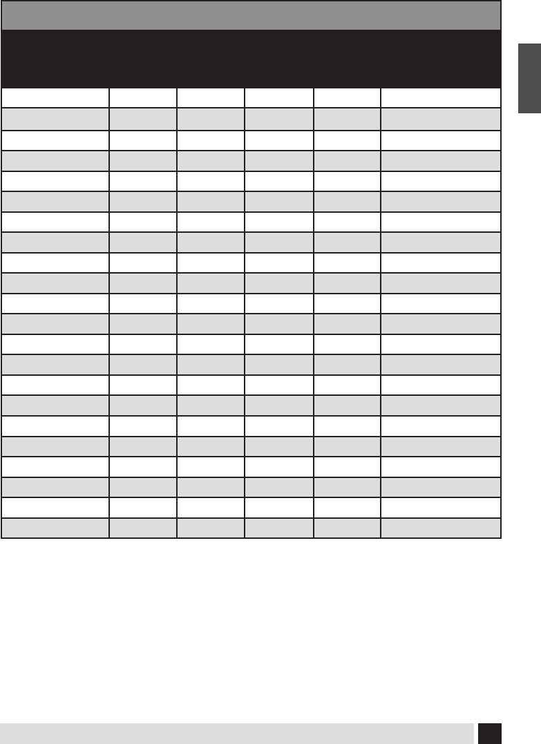
Number Meaning
1
The heater will remain running with pump(s) on high speed.
2
The heater can be activated only with the pump on low speed. Only the spa light
can be operating at the same time without disabling the heater. See your autho-
rized dealer to select this option.
INSTRUCTIONS:
Find your spa listed within the charts on pages 16-20 of this manual then refer to
the key below to determine what electrical service your spa requires.
SECTION Z:
APPLIES TO SPAS
INSTALLED OUTSIDE OF
NORTH AMERICA

18
Owner’s Manual
English
DEDICATED 240V UNITS WITHOUT BLOWER
MODELS
NORTH AMERICA
NOT NORTH
AMERICA
240V/60A 240V/50A 240V/40A 240V/30A 240V/50Hz
9000 B1 C2 Z
8500
B1 C2 Z
8000 B1 C2 Z
7500 B1 C2 Z
7000 B1 C2 Z
5600 A1 C2 Z
5400 A1 C2 Z
5300 A1 C2 Z
5200 A1 C2 Z
5100 (240V) C1 D2 Z
4600 B1 D2 Z
4400 B1 D2 Z
4300 B1 D2 Z
4200 B1 D2 Z
4100 C1 D2 Z
811
A1 C2 Z
781 A1 C2 Z
780 A1 C2 Z
581 A1 C2 Z
482 A1 C2 Z
481 A1 C2 Z
480 A1 C2 Z
472 A1 C2 Z
471 A1 C2 Z
470 A1 C2 Z
461 A1 C2 Z
451 C1 D2 Z
381 B1 C2 Z
See page 16 for explanation of corresponding letters and numbers.

19
Owner’s Manual
English
See page 16 for explanation of corresponding letters and numbers.
DEDICATED 240V UNITS WITHOUT BLOWER (continued)
MODELS
NORTH AMERICA
NOT NORTH
AMERICA
240V/60A 240V/50A 240V/40A 240V/30A 240V/50Hz
380 B1 C2 Z
371
B1 C2 Z
370 B1 C2 Z
311 B1 D2 Z
Amour B1 C2 Z
Cabaret A1 C2 Z
Chateau A1 C2 Z
Elegant A1 C2 Z
Envie A1 C2 Z
ES A1 Z
ESR A1 C2 Z
ESX A1 C2 Z
Fontaine A1 C2 Z
Grand A1 C2 Z
Intrigue B1 C2 Z
Joli
A1 C2 Z
Monarque A1 C2 Z
Mystique A1 C2 Z
Nuage A1 C2 Z
Prestige A1 C2 Z
Rendezvous A1 C2 Z
Trio C1 D2 Z

20
Owner’s Manual
English
See page 16 for explanation of corresponding letters and numbers.
DEDICATED 240V UNITS WITH BLOWER
MODELS
NORTH AMERICA
NOT NORTH
AMERICA
240V/60A 240V/50A 240V/40A 240V/30A 240V/50Hz
9000 A1 C2 Z
8500
A1 C2 Z
8000 A1 C2 Z
7500 A1 C2 Z
7000 A1 C2 Z
5600 A1 C2 Z
5400 A1 C2 Z
5300 A1 C2 Z
5200 A1 C2 Z
5100 (240V) B1 C2 Z
4600 A1 C2 Z
4400 A1 C2 Z
4300 A1 C2 Z
4200 A1 C2 Z
4100 B1 D2 Z
811
A1 C2 Z
781 A1 C2 Z
780 A1 C2 Z
581 A1 C2 Z
482 A1 C2 Z
481 A1 C2 Z
480 A1 C2 Z
472 A1 C2 Z
471 A1 C2 Z
470 A1 C2 Z
461 B1 C2 Z
451 C1 D2 Z
381 A1 C2 Z
21
Owner’s Manual
English
See page 16 for explanation of corresponding letters and numbers.
DEDICATED 240V UNITS WITH BLOWER (continued)
MODELS
NORTH AMERICA
NOT NORTH
AMERICA
240V/60A 240V/50A 240V/40A 240V/30A 240V/50Hz
380 A1 C2 Z
371
A1 C2 Z
370 A1 C2 Z
311 B1 D2 Z
Amour B1 C2 Z
Cabaret A1 C2 Z
Chateau A1 C2 Z
Elegant A1 C2 Z
Envie A1 C2 Z
ES A1 Z
ESR A1 C2 Z
ESX A1 C2 Z
Fontaine A1 C2 Z
Grand A1 C2 Z
Intrigue B1 C2 Z
Joli
A1 C2 Z
Monarque A1 C2 Z
Mystique A1 C2 Z
Nuage A1 C2 Z
Prestige A1 C2 Z
Rendezvous A1 C2 Z
Trio C1 D2 Z

22
Owner’s Manual
English
CONVERTIBLE UNITS WITH GFCI CORD
Model
Cord Connected
120V/30A
Cord Connected
120V/15A
Cord Included
120V/30A
Cord Included
120V/15A
101 F1 H2
M50 F1 H2
M61 F1 H2
M71 F1 H2
Duet F1 H2
Image F1 H2
Forte F1 H2
Voeux F1 H2
CONVERTIBLE UNITS WITHOUT GFCI CORD
Model 120V/40A 120V/20A 240V/50A 240V/40A
5100 (120V)
E1 G2 H1 C2
102 E1 G2 H1 C2
103 E1 G2 H1 C2
Cirque E1 G2 H1 C2
NOTE: Units included in “Convertible Units with GFCI Cord” chart (above) leave the factory as
120V units and can be converted up to 240V units. See chart (below) “GFCI Cord Units After
Conversion” for voltage and amperage requirements after conversion to a 240V unit.
NOTE: If you order the 5100 as a 120V model it leaves the factory as a 120V unit and can be
converted up to 240 Volts. The 102, 103 and Cirque leave the factory as 240V units and can be
converted down to 120 Volts. Electrical service requirements will change after conversion.
GFCI CORD UNITS AFTER CONVERSION
Model 240V/40A 240V/30A
101 C1 D2
M50 C1 D2
M61 C1 D2
M71 C1 D2
Duet C1 D2
Image C1 D2
Forte C1 D2
Voeux C1 D2
Applicable to North American Spas Only.
See page 16 for explanation of corresponding letters and numbers.

23
Owner’s Manual
English
START UP PROCEDURES
Follow recommendations for site location
and electrical connection. 6” (15.5cm) below
the top lip of the spa is the level at which the
water should be maintained.
1. Fill the spa through the lter hole to 6”
(15.5cm) below the top of the spa with tap
water. Never use ‘softened’ water in
your spa. Softened water can impact the
chemical balance of the water and lead to
degradation of metal plumbing ttings
and possible jet plastic damage.
2. Turn power on to unit at circuit breaker or
disconnect panel.
3. Open the air controls, located on the top
lip, and cycle the jets from high to low.
Water should come from the therapy jets.
If water ow is not established, turn o jets
and see Priming Your Spa (next column).
4. Add chemicals. Ask your dealer for
additional information.
5. Verify all drain valves are closed, some are
under the spa.
Follow Operating Instructions for your
particular model to set heat to the desired
temperature. Initially you may nd that
the spa requires 12 to 14 hours on 230 Volt
installations to reach temperature. Keep your
thermal cover on the unit and close the air
controls to help the heating process.
Priming Your Spa
When lling your spa for the rst time or
after draining and relling the spa, you
may need to bleed air from the system.
Should you experience an air-lock on
Pump 1, remove the lter cover,
insert a garden hose through each center
hole that holds the lter as far as possible
without using force. Hold the hose in place
and turn on the water. Cycle pump 1 from low
to high several times, this forces water into the
pump and forces the air out. If this does not
work or you experience an air-lock on Pump 2,
remove the side panel and locate the pump.
With the pump on high speed, slowly loosen
the discharge (top) pump union until water
starts to trickle out. Once water is trickling out,
hand tighten the union (do not over tighten
as this could cause the union to crack) and
replace the side panel.
Pr - This is Not an Error Message
The Spa has just been powered up and is in
Priming Mode for 4 Minutes. Pumps can be
turned ON and OFF to remove any air from
the plumbing lines and the Heater. Cycle the
pumps on and o to verify good water ow
and wait 4 minutes or press any temp related
button to exit Priming Mode.
Important: Do not operate the spa
without full water ow.

24
Owner’s Manual
English
Spa Status
Important information about spa operation
can be seen on the Main Screen. Most
features, including Set Temperature
adjustment, can be accessed from this screen.
The actual water temperature and Set
Temperature can be seen, and the Set
Temperature can be adjusted (see page
4). Time-of-Day, Ozone and Filter status is
available, along with other messages and
alerts. The selected Temperature Range is
indicated in the upper right corner. The Jets
Icon in the center will spin if any pump is
running and changes color when the heater
is on. A Lock icon is visible if the panel or
settings are locked.
The Menu choices on the right can be
selected and the screen will change to show
more detailed controls or programming
functions.
Navigation
Navigating the entire menu structure is done
by touching the screen. When a text item
is shown in white on the main screen, it is
selectable. The menu selections on the right
side of the screen can be selected. Select
one of these to enter a dierent screen with
additional controls. Most menu screens time
out and revert to the main screen after 30
seconds of no activity.
The only item that can be changed on the left
side of the Main Screen is the Set Temperature.
Touch either the set temperature line or
the water temperature to go to the Set
Temperature screen. See next page.
SMART TOUCH WATERPROOF DISPLAY
MAIN SCREEN

25
Owner’s Manual
English
Set Temperature
Press Inc or Dec to modify the Set Temperature.
The Set Temperature changes immediately.
Press Back to return to the Main Screen.
If you need to switch between high range
and low range you need to go to the Settings
Screen.
Press-and-Hold
If the Up or Down button is pressed and held,
the temperature will continue to change until
the button is released, or the Temperature
Range limits are reached.
SET TEMPERATURE SCREEN
All Equipment Access
The Spa Screen shows all available equipment
to control, as well as other features, like Invert.
The display shows icons that are related to the
equipment installed on a particular spa model,
so this screen may change depending on the
installation. The icon buttons are used to select
and control individual devices. Some devices,
like pumps, may have more than one ON state,
so the icon will change to reect the state that
the equipment is in. Below are some examples
of 2-speed Pump indicators.
SPA SCREEN
If the Spa has a Circ Pump, a Circ Pump Icon
will appear to indicate its activity, but outside
of Priming Mode, the Circ Pump cannot be
controlled directly.
NOTE: The icon for the pump that is
associated with the heater (Circ or P1 Low)
will have a red glow in the center when the
heater is running.

26
Owner’s Manual
English
Exiting Screen
When you see both of these buttons, whether they are labeled or not, they always mean Save
and Cancel. They appear on most editing screens once you have changed the value on that
screen.
COMMON BUTTONS
If the screen times out due to no activity it will act like Cancel.
When you see only this button, whether it is labeled or not, it means Back or Exit. It appears on
editing screens before you have changed any value, as well as on all other screens.

27
Owner’s Manual
English
Page Up/Down
If an Up or Down button is shown and pressed when in a Menu List, the list can be scrolled a
page at a time. The scroll bar on the right side of the screen indicates the relative position of
the page.
COMMON BUTTONS
Values Increment/Decrement
If an Up or Down button is shown and pressed when on an editing page, and a value has been
selected (highlighted), the value can be incremented by pressing the up arrow or decremented
by pressing the down arrow.

28
Owner’s Manual
English
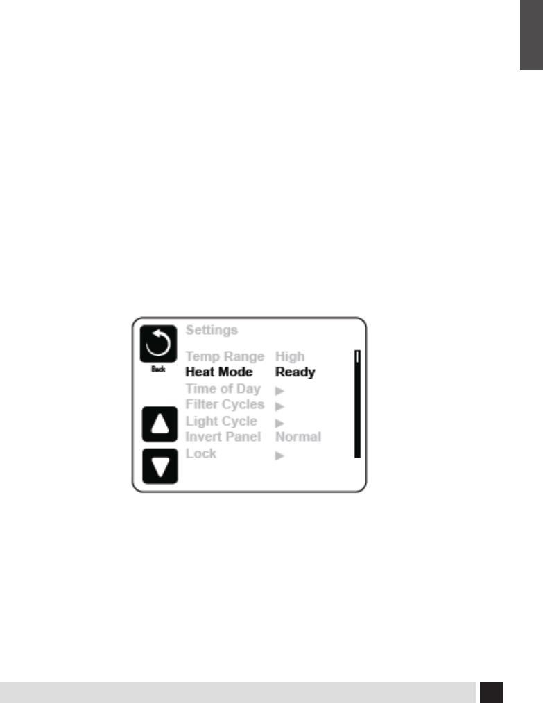
Programming, Etc.
The Settings Screen is where all programming and other spa behaviors are controlled.
This screen has several features that can be acted on directly. These features may include Temp
Range, Heat Mode, Hold, and Invert Panel. When one of these items is selected, it will toggle
between two settings. All other menu items (with an arrow pointing to the right) go to another
level in the menu.
SETTINGS SCREEN
Dual Temperature Ranges (High vs. Low)
This system incorporates two temperature range settings with independent set temperatures.
The specic range can be selected on the Settings screen and is visible on the Main Screen in the
upper right corner of the display.
These ranges can be used for various reasons, with a common use being a “ready to use” setting
vs. a “vacation” setting. Each range maintains its own set temperature as programmed by the
user. This way, when a range is chosen, the spa will heat to the set temperature associated with
that range.
High Range can be set between 80°F and 104°F (26˚C - 40˚C).
Low Range can be set between 50°F and 99°F (10˚C - 26˚C).
Freeze Protection is active in either range.
29
Owner’s Manual
English
Heat Mode – Ready vs. Rest
In order for the spa to heat, a pump needs to circulate water through the heater. The pump that
performs this function is known as the “heater pump.” The heater pump can be either a 2-speed
pump (Pump 1) or a circulation pump. If the heater pump is a 2-Speed Pump 1, Ready Mode
will circulate water every 1/2 hour, using Pump 1 Low, in order to maintain a constant water
temperature, heat as needed, and refresh the temperature display. This is known as “polling.”
Rest Mode will only allow heating during programmed lter cycles. Since polling does not occur,
the temperature display may not show a current temperature until the heater pump has been
running for a minute or two. When the heater pump has come on automatically (for example
for heating) you can switch between low speed and high speed but you cannot turn the heater
pump o.
Circulation Mode (See Page 30, under Pumps, for other circulation modes)
If the spa is congured for 24HR circulation, the heater pump generally runs continuously. Since
the heater pump is always running, the spa will maintain set temperature and heat as needed
in Ready Mode, without polling. In Rest Mode, the spa will only heat to set temperature during
programmed lter times, even though the water is being ltered constantly when in 24HR
circulation mode.
SETTINGS SCREEN
Ready-in-Rest Mode
Ready in Rest Mode appears in the display if the spa is in Rest Mode and the Jets 1 Button is
pressed. When the heater pump has come on automatically (for example for heating) you can
switch between low speed and high speed but you cannot turn the heater pump o. After 1
hour, the System will revert to Rest Mode. This mode can also be reset by entering the Settings
Menu and selecting the Heat Mode line.

30
Owner’s Manual
English
Preparation and Filling
Fill the spa to its correct operating level (6”/15.5cm below the top of the the spa). Be sure to open
all valves and jets in the plumbing system before lling to allow as much air as possible to escape
from the plumbing and the control system during the lling process. After turning the power on
at the main power panel, the top-side panel will display a splash screen or startup screen.
Priming Mode – M019*
After the initial start-up sequence, the control will enter Priming Mode and display a Priming
Mode screen. Only pump icons appear on the priming mode screen. During the priming mode,
the heater is disabled to allow the priming process to be completed without the possibility of
energizing the heater under low-ow or no-ow conditions. Nothing comes on automatically,
but the pump(s) can be energized by selecting the “Jet” buttons. If the spa has a Circ Pump, it can
be turned on and o by pressing the “Circ Pump” button during Priming Mode.
Priming the Pumps
As soon as the Priming Mode screeen appears
on the panel, select the “Jets 1” button once to
start Pump 1 in low-speed and then again to
switch to high-speed. Also, select the other
pumps, to turn them on. The pumps should be
running in high-speed to facilitate priming. If
the pumps have not primed after 2 minutes,
and water is not owing from the jets in the
spa, do not allow the pumps to continue to run.
Turn o the pumps and repeat the process.
Note: Turning the power o and back on again
will initiate a new pump priming session.
Sometimes momentarily turning the pump o
and on will help it to prime. Do not do this
more than 5 times. If the pump(s) will not
prime, shut o the power to the spa and
call for service.
Important: A pump should not be allowed to run without priming for more than 2 minutes.
Under NO circumstances should a pump be allowed to run without priming beyond the end
of the 4-5 minute priming mode. Doing so may cause damage to the pump and cause the
system to energize the heater and go into an overheat condition.
FILL IT UP!

31
Owner’s Manual
English
Exiting Priming Mode
The system will automatically enter the normal heating and ltering at the end of the priming
mode, which lasts 4-5 minutes. You can manually exit Priming Mode by pressing the “Exit”
button on the Priming Mode Screen. Note that if you do not manually exit the priming mode as
described above, the priming mode will be automatically terminated after 4-5 minutes.
Be sure that the pump(s) have been primed by this time. Once the system has exited Priming
Mode, the top-side panel will display the Main Screen, but the display will not show the
temperature yet, as shown below. This is because the system requires approximately 1 minute of
water owing through the heater to determine the water temperature and display it.
– – –°F – – –°C
FILL IT UP!
Pumps
On the Spa Screen, select a “Jets” button once to turn the pump on or o, and to shift between
low- and high-speeds if equipped. If left running, the pump will turn o after a time-out period.
Non-Circ Systems
The low-speed of pump 1 runs when the blower or any other pump is on. If the spa is in Ready
Mode (See page 9), Pump 1 low may also activate for at least 1 minute every 30 minutes to detect
the spa temperature (polling) and then to heat to the set temperature if needed. When the low-
speed turns on automatically, it cannot be deactivated from the panel, however the high speed
may be started.
Circulation Pump Modes
If the system is equipped with a circ pump, the circ pump operates continuously (24 hours) with
the exception of turning o for 30 minutes at a time when the water temperature reaches 3°F
(1.5°C) above the set temperature
SPA BEHAVIOR
32
Owner’s Manual
English
Filtration and Ozone
On non-circ systems, Pump 1 low and the ozone generator will run during ltration. On circ
systems, the ozone will generally run with the circ pump. The system is factory-programmed
with one lter cycle that will run in the evening (assuming the time-of-day is properly set) when
energy rates are often lower. The lter time and duration are programmable. (See page 32) A
second lter cycle can be enabled as needed. At the start of each lter cycle, devices like the
blower and other pumps will run briey to purge the plumbing to maintain good water quality.
Freeze Protection
If the temperature sensors within the heater detect a low enough temperature, then the water
devices automatically activate to provide freeze protection. The water devices will run either
continuously or periodically depending on conditions.
Clean-up Cycle (optional)
When a pump or blower is turned o by a button press or after it has timed out, a clean-up cycle
runs for 30 minutes. Pump 1 on Low Speed and the ozone generator will run for the set time..
The pump and the ozone generator will run for 30 minutes or more, depending on the system.
On some systems, you can change this setting.
SPA BEHAVIOR
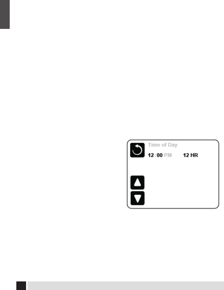
Be sure to set the Time-of-Day
Setting the time-of-day is important for deter-
mining ltration times and other background
features.
“Set Time” will appear on the display if no time-
of-day is set in the memory.
On the Settings Screen, select the Time-of-Day
line. On the Time-of-Day screen, simply select
the Hour, Minutes, and 12/24 Hour segments.
Use the Up and Down Buttons to make
changes.
TIME OF DAY
Note: This only applies to some systems: If power is interrupted to the system, Time-of-Day will be
maintained for several days.

33
Owner’s Manual
English
Main Filtration
Using the same adjustment as Setting the Time, Filter Cycles are set using a start time and a
duration. Each setting can be adjusted in 15-minute increments. The panel calculates the end
time and displays it automatically.
ADJUSTING FILTRATION
Filter Cycle 2 - Optional Filtration
When a lter cycle is OFF it displays as “No”. When a Filter Cycle is ON it displays as “Yes”.
Press “Yes” or “No” to toggle Filter Cycle 2 ON or OFF. When Filter Cycle 2 is ON, it can be adjusted
in the same manner as Filter Cycle 1. It is possible to overlap Filter Cycle 1 and Filter Cycle 2,
which will shorten overall ltration by the overlap amount.
Purge Cycles
In order to maintain sanitary conditions, as well as protect against freezing, secondary water
devices will purge water from their respective plumbing by running briey at the beginning of
each lter cycle. If the Filter Cycle 1 duration is set for 24 hours, enabling Filter Cycle 2 will initiate
a purge when Filter Cycle 2 is programmed to begin.
The Meaning of Filter Cycles
1. The heating pump always runs during the lter cycle
2. In Rest Mode, heating only occurs during the lter cycle
3. Purges happen at the start of each lter cycle

34
Owner’s Manual
English
Light Cycle Option
If Light Cycle does not appear in the Settings
Menu, the Light Timer feature is not enabled
by the manufacturer. When available, the Light
Timer is OFF by default. The settings can be ed-
ited the same way that Filter Cycles are edited
(see page 13).
Invert Panel
Selecting Invert Panel will ip the display
and the buttons so the panel can be easily
operated from inside or outside the hot tub.
ADDITIONAL SETTINGS
Specic Buttons for Specic Devices
If the spa has an Auxiliary Panel(s) installed, pressing buttons on that panel will activate the
device indicated for that button. These dedicated buttons will operate just like the Spa Screen
buttons (see page 5) and the equipment will behave in the same manner with each button press.
AUXILIARY PANEL(S)
The control can be restricted to prevent unwanted use or
temperature adjustments. Locking the Panel prevents the
controller from being used, but all automatic functions
are still active. Locking the Settings allows Jets and other
features to be used, but the Set Temperature and other pro-
grammed settings cannot be adjusted. Settings Lock allows
access to a reduced selection of menu items.
These include Filter Cycles, Invert, Information and Fault Log.
They can be seen, but not changed or edited.
RESTRICTING OPERATION
35
Owner’s Manual
English
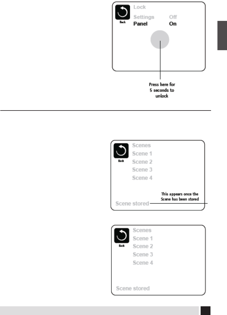
To Unlock
To unlock either Settings or Panel rst select
Settings (if it says “On”) or Panel (if it says “On”),
than press in the middle of the screen for at
least 5 seconds.
UNLOCKING
What are Scenes?
Scenes are stored combinations of equipment
states. For example if you want to have Pump
1 at high speed and Pump 2 at low speed and
the Light ON, you could store that in a Scene
and recall this combination at any time.
Storing a Scene
Press a Scene number and hold until “Scene
stored“ appears at the bottom of the screen to
save the current equipment combination.
Recalling a Scene
To recall a Scene simply press a Scene number.
Pressing any Scene line which has not yet been
stored will simply turn o all spa devices.
SCENES

36
Owner’s Manual
English
ADDITIONAL SETTINGS
GFCI Test
(Feature not available on CE rated systems.)
Your systems may have GFCI congured in one
of three ways:
1. Both manual and automatic GFCI tests are
enabled. The automatic test will happen within
7 days of the spa being installed and if success-
ful will not repeat. (If the automatic test fails it
will repeat after the spa is restarted.)
GFCI Test will not appear on the screen if it is
not enabled. This screen allows the GFCI to be
tested manually from the panel and can be
used to reset the automatic test feature.
(See Page 38)
*M0XX is a Message Code. Codes like this will be
seen in the Fault Log
Preferences
The Preferences Menu allows the user to
change certain parameters based
on personal preference.
Temp Display
Change the temperature between Fahrenheit
and Celsius.
Time Display
Change the clock between 12 hr and 24 hr
display.
Reminders
Turn the reminder messages (like “Clean Filter”)
On or O.
Cleanup
Cleanup Cycle Duration is not always enabled,
so it may not appear. When it is available, set
the length of time Pump 1 will run after each
use. 0-4 hours are available.
Color
Selecting Color will cycle through 5 back-
ground colors available in the control.
Language
Change the language displayed on the panel.

37
Owner’s Manual
English
System Information
The System Information Menu displays various
settings and identication of the particular
system. As each item in the menu is selected,
the detail for that item is displayed at the
bottom of the screen.
Software ID (SSID)
Displays the software ID number for the
System.
System Model
Displays the Model Number of the System.
Current Setup
Displays the currently selected Conguration
Setup Number.
Conguration Signature
Displays the checksum for the system congu-
ration le.
Heater Voltage (Feature not used on CE
rated systems.)
Displays the operating voltage congured for
the heater.
Heater Wattage as Congured in Software
(CE Systems Only.)
Displays a heater kilowatt rating as pro-
grammed into the control system software (1-3
or 3-6).
Heater Type
Displays a heater type ID number.
INFORMATION
Dip Switch Settings
The System Information Menu displays various
settings and identication of the particular
system. As each item in the menu is selected,
the detail for that item is displayed at the
bottom of the screen.
Panel Version
Displays a number of the software in the top-
side control panel.
Note: Do not attempt to change any of the
above info or settings.

38
Owner’s Manual
English
GFCI Safety Feature
The Ground Fault Circuit Interrupter (GFCI) or
Residual Current Detector (RCD) is an impor-
tant safety device and is required
equipment on a hot tub installation.
(The GFCI Test Feature is not available on CE rated
systems.)
Used for verifying a proper installation
Your spa may be equipped with a GFCI
Protection feature. If your spa has this feature
enabled the GFCI Trip Test must occur to allow
proper spa function.
UTILITIES – GFCI TEST FEATURE
Within 1 to 7 days after startup, the spa will trip the GFCI to test it.
The GFCI must be reset once it has tripped. After passing the GFCI Trip Test, any subsequent GFCI
trips may indicate a ground fault or other unsafe condition. Reset the GFCI breaker. It it will not
reset, contact your dealer.
Forcing the GFCI Trip Test (North America Only)
The installer can cause the GFCI Trip Test to occur sooner by initiating it using the above menu.
The GFCI should trip within several seconds and the spa should shut down. If it does not, shut
down the power and manually verify that a GFCI breaker is installed and that the circuit and spa
are wired correctly. Verify the function of the GFCI with its own test button. Restore power to the
spa and repeat the GFCI Trip Test. Once the GFCI is tripped by the test, reset the GFCI and the spa
will operate normally from that point. You can verify a successful test by navigating to the above
menu. “Passed” should appear after the Reset line is selected on the GFCI screen.
Warning:
On those systems that automatically test the GFCI within 1 to 7 days after startup:
The end-user must be trained to expect this one-time test to occur.
The end-user must be trained how to properly reset the GFCI.
If freezing conditions exist, the GFCI or RCD should be reset immediately or spa damage could
result.
CE Product:
CE registered systems do not have an RCD Test Feature due to the nature of the electrical service.
Some UL registered systems do not have the GFCI Test Feature activated.
The end-user must be trained how to properly test and reset the RCD.

39
Owner’s Manual
English
Messages
Most messages and alerts will appear at the bottom of the normally used screens.
Several alerts and messages may be displayed in a sequence.
– – –°F – – –°C
Water Temperature is Unknown
After the pump has been running for 1 minute, the temperature will be displayed.
Possible freezing condition
A potential freeze condition has been detected. All water devices are activated. In some cases,
pumps may turn on and o and the heater may operate during Freeze Protection. This is an
operational message, not an error indication.
The water is too hot – M029*
The system has detected a spa water temp of 110°F (43.3°C) or more, and spa functions are
disabled. System will auto reset when the spa water temp is below 108°F (42.2°C). Check for
extended pump operation or high ambient temp.
*M0XX is a Message Code. Codes like this will be seen in the Fault Log
GENERAL MESSAGES

40
Owner’s Manual
English
REMINDER MESSAGES
General maintenance helps.
Reminder Messages can be suppressed by using the Preferences Menu. See Page 18.
Reminder Messages can be chosen individually by the Manufacturer. They may be disabled en-
tirely, or there may be a limited number of reminders on a specic model. The frequency of each
reminder (i.e. 7 days) can be specied by the Manufacturer.
Check the pH
May appear on a regular schedule, i.e. every 7 days. Check pH with a test kit and adjust pH with
the appropriate chemicals.
Check the sanitizer
May appear on a regular schedule, i.e. every 7 days. Check sanitizer level and other water chemis-
try with a test kit and adjust with the appropriate chemicals.
Clean the lter
May appear on a regular schedule, i.e. every 30 days.
Clean the lter media as instructed by the manufacturer. See HOLD on page 17.
Test the GFCI (or RCD)
May appear on a regular schedule, i.e. every 30 days. The GFCI or RCD is an important safety de-
vice and must be tested on a regular basis to verify its reliability. Every user should be trained to
safely test the GFCI or RCD associated with the hot tub installation. A GFCI or RCD will have a TEST
and RESET button on it that allows a user to verify proper function.
Change the water
May appear on a regular schedule, i.e. every 90 days. Change the water in the spa on regular basis
to maintain proper chemical balance and sanitary conditions.
Clean the cover
May appear on a regular schedule, i.e. every 180 days. Vinyl covers should be cleaned and condi-
tioned for maximum life.
Change the lter
May appear on a regular schedule, i.e. every 365 days.
Filters should be replaced occasionally to maintain proper spa function and sanitary conditions.
Additional messages may appear on specic systems.

41
Owner’s Manual
English
The 300 Control System oers you simplicity in
spa control. The backlit, Liquid Crystal Display
(LCD) displays current temperature, set water
temperature, and operating mode settings.
Each feature is actuated through the control
panel pad. Touch the appropriate button to
activate the desired function.
At start up, when power is supplied to the spa,
the controls will operate properly and safely
under the factory settings. The spa will be in
Standard mode, have a temperature setting of
100°F (38°C), and a ltration cycle duration of
1 hour. To fully utilize the unique capabilities
of the control system, it is important to know
how to set the temperature, operate the
pumps, operate the light, adjust the mode
setting, and change the ltration cycle.
Note: In event of a power outage or failure,
the 300 Series Control System may retain
settings. If settings are lost, re-program per
the instructions in this manual.
NOTE: Some spas using the 300 control
panel come with a cord connection. See
page 14 for special installation instructions
for these spas.
User’s Pads
User’s Pads are the buttons located on the
topside control panel and are used to program
various spa functions (i.e., turn on spa light, set
temperature, etc.). The following table denes
the buttons:
Pad Use
• Decrease temperature
• Increase temperature
• Switch modes
• Change ler cycle durations
• Turn internal spa light on or o
• Switch modes
• Activate therapy pump
• Set duration of lter cycles
300 CONTROL PANEL
NOTE: The look of your topside control panel design and buttons will vary according to brand.
See table below for pictures and explanation of 300 Control Panel button functions.

42
Owner’s Manual
English
1 touch = Low therapy jets
2 touches = High therapy jets
3 touches = O
The low speed operation of Pump 1 is timed
to automatically turn o after two hours
of operation. The high speed operation of
Pump 1 is timed to automatically turn o
after 15 minutes of operation.
NOTE: With the standard conguration,
pump 1 will automatically operate in
low speed whenever the spa calls for a
ltration cycle or heat. When this automatic
activation occurs, the low speed of Pump
1 cannot be turned o; however, all other
control functions can be activated.
MODES OF OPERATION
In the standard conguration your spa can be
switched among Standard, Economy, and
Sleep modes by touching the ‘TEMP’ pad and
then the ‘LIGHT’ pad.
If your spa is in the
Standard mode,
the low speed of Pump 1 and the heater
will come on automatically to maintain the
set temperature of the water. The pump
will circulate for approximately one minute
several times throughout the day to sample
water temperature. If your spa is set in:
Economy mode,
the heater will operate ONLY during the
ltration cycles. If your spa is set in the
Sleep mode,
the spa will heat to within 20°F (11°C) of the
set temperature only during lter cycles.
The pump will operate either during a normal
ltration cycle or, the heater and pump
will be activated when the heater housing
temperature drops below 45°F (7.2°C).
The selected mode will be displayed in the
LCD window of the control panel.
Temperature Controls
The maximum set temperature is 104°F (40°C)
and the minimum set temperature is 80°F
(26°C). The current water temperature or, if
the pump has not been running, two dashes,
will show on the display. If dashes are
displayed, you must rst start the pump by
pressing the PUMP 1 pad. Wait until the water
temperature is displayed (approximately 1
minute).
The set temperature of your spa may easily
be increased or decreased at any time using
the ‘TEMP’ pad. Press the ‘TEMP’ pad; the
set temperature will be displayed in the
LCD window. The next touch of ‘TEMP’ will
change the set temperature either up or
down 1°F (0,5°C). If you want to increase
the temperature and the displayed indicates
the temperature was increased by 1°F (0,5°C),
continue to press the ‘TEMP’ pad until the
desired set temperature is reached.
If you want to decrease the set temperature
and the LCD indicates that the temperature is
increasing, STOP. Wait a few seconds until the
actual temperature is displayed. Then press
the ‘TEMP’ pad again. The set temperature
will be displayed. Press it again and the set
temperature will decrease by 1°F (0,5°C).
Continue pressing the ‘TEMP’ pad until the
desired set temperature is reached.
If the spa is set in Standard mode or in a
ltration cycle, increasing the set temperature
may result in activating the heater. Decreasing
the set temperature will turn the heater o.
When the heater is operating, the LED below
the ‘HEAT’ icon will be lit.
Pump 1
Touch the ‘JETS’ pad to activate the primary
ltration pump. The sequence of the jet action is:

43
Owner’s Manual
English
hour increments of 1- 8. For example, a 2
hour cycle will complete once every 12 hours
for a total of 4 hours per day. The amount of
time needed to lter your spa will depend on
usage and ambient conditions.
You will need to program your lter cycles
based upon your personal use.
To change the duration of the lter cycles
touch the ‘TEMP’ pad and then touch the
‘JETS’ pad. Touch the ‘TEMP’ pad to adjust
the cycle duration to the desired setting. After
each press, the duration of the cycle will be
displayed in the LCD window as follows:
F1 1 Hours for each cycle, 2 hours per day
F2 2 Hours for each cycle, 4 hours per day
F3 3 Hours for each cycle, 6 hours per day
F4 4 hours for each cycle, 8 hours per day
F5 5 hours for each cycle, 10 hours per day
F6 6 Hours for each cycle, 12 hours per day
F7 7 Hours for each cycle, 14 hours per day
F8 8 Hours for each cycle, 16 hours per day
To exit the lter-set procedure, touch ‘JETS’.
The LCD window will display the current water
temperature.
If a change is made to the duration while the
spa is in a ltration cycle, it will take eect
immediately. If the change is made outside a
ltration cycle, it will take eect at the start of
the next scheduled cycle.
NOTE: When power to the spa is denied
(disconnect, power outage), the controls
may revert to the default factory settings.
Any adjustments to set temperature
or lter cycle duration may need to be
reprogrammed.
Light
Touch the ‘LIGHT’ pad to turn all lights on and
o. The lights will automatically turn o after 4
hours of operation.
When in Standard mode, the letters ‘ST’
are displayed beiey, followed by the water
temperature. When in Economy mode, the
letters ‘EC’ are
displayed alternately with the
water temperature.
When in Sleep mode, the letters ‘SL’ are
displayed alternately with the water temperature.
Setting the Time and Filtration Cycles
You can decide when your lter cycles start
and how long they run.
Preset Filter Cycles. The spa control system
is designed with two lter cycles. The rst
lter cycle turns on 6 minutes after power is
supplied to the spa. The second lter cycle
turns on 12 hours later. Filter cycles are pre-set
for a two hour duration.
Note: To properly clean and maintain spa, a
total lter time of at least two hours per day
is recommended. If an ozonator is installed,
4 hours is recommended.
Changing Filter Cycle Start Time
The start/stop times of the lter cycle
correspond to 6 minutes after the spa set
time is established. Set time is based on the
time of day that the spa is powered up. Set
time may only be changed by disconnecting
power from the spa and re-connecting it at
the desired start time. For example, if you
want the lter cycle to begin at 9:00 PM,turn
o the spa breaker and turn it back on at 8:54
PM (remember the 6 minute wait period). The
cycle will begin at 9:00 PM and will repeat
beginning at 9:00 AM. Each cycle will run for
the prescribed
number of hours.
Changing Filter Cycle Duration
The duration of a lter cycle can be set in one

44
Owner’s Manual
English
The 501 Controls oer you simplicity in spa
control. The backlit, Liquid Crystal Display
(LCD) displays current temperature, set water
temperature, and operating mode settings.
Each feature is actuated through the control
panel pad.
Touch the appropriate button to activate
the desired function.
At start up, when power is supplied to the
spa, the controls will operate properly and
safely under the factory settings. The spa will
be in Standard mode, have a temperature
setting of 100°F (38°C), and a ltration
cycle duration of 2 hours. To fully utilize the
unique capabilities of the control system,
it is important to know how to set the
temperature, operate the pumps, operate the
light, adjust the mode setting, and change the
ltration cycle durations.
If your Topside Control
looks like this, your spa
has the following features:
• Internal Lights
• 1 Pump 2 speed
If your Topside Control
looks like this, your spa
has the following features:
• Internal Lights
• 1 Pump 2 speed
• Blower
501 CONTROL PANEL
NOTE: The look of your topside control panel design and buttons will vary according to brand.
See next page for pictures and explanation of 501 Control Panel button functions.

45
Owner’s Manual
English
Temperature controls
The maximum set temperature is 104°F (40°C)
and the minimum set temperature is 80°F
(26°C). The current water temperature or, if
the pump has not been running, two dashes,
will show on the display. If dashes are
displayed, you must rst start the pump by
pressing the JETS pad. Wait until the water
temperature is displayed (approximately 2
minutes).
The set temperature of your spa may easily be
increased or decreased at any time using the
‘TEMP’ pad. Either the actual temperature or
2 dashes will be displayed. Press the ‘TEMP’
pad; the set temperature will be displayed in
the LCD window. The next touch of ‘TEMP’
will change the set temperature either up
or down 1°F (0,5°C). If you want to increase
the temperature and the displayed indicates
the temperature was increased by 1°F (0,5°C),
continue to press the ‘TEMP’ pad until the
desired set temperature is reached.
If you want to decrease the set temperature
and the LCD indicates that the temperature is
increasing, STOP. Wait a few seconds until the
actual temperature is displayed. Then press
the ‘TEMP’ pad again. The set temperature
will be displayed. Press it again and the set
temperature will decrease by 1°F (0,5°C).
Continue pressing the ‘TEMP’ pad until the
desired set temperature is reached.
If the spa is set in Standard mode or in a
ltration cycle, increasing the set temperature
may result in activating the heater. Decreasing
the set temperature will turn the heater
o. When the heater is operating, the LCD
indicator below the ‘TEMP’ icon will be lit.
User’s Pads
User’s Pads are the buttons located on the
topside control panel and are used to program
various spa functions (i.e., turn on spa light, set
temperature, etc.). The following table denes
the buttons:
Pad Use
• Decrease temperature
• Increase temperature
• Change ler durations
• Turn internal spa light
on or o
• Switch modes
• Set duration of lter
cycles
• Activate therapy pump
• Optional
• Turns blower system
on or o
• Same as Turbo

46
Owner’s Manual
English
The selected mode will be displayed in the
LCD window of the control panel.
When in Standard mode, the letters ‘ST’ are
displayed, followed by the water temperature.
When in Economy mode, the letters ‘EC’ are
displayed alternately with the water temperature.
When in Sleep mode, the letters ‘SL’ are
displayed alternately with the water temperature.
Setting the Time and Filtration Cycles
Preset Filter Cycles. The spa control system
is designed with two lter cycles. The rst
lter cycle turns on 6 minutes after power is
supplied to the spa. The second lter cycle
turns on 12 hours later. Filter cycles are pre-set
for a two hour duration.
NOTE: To properly clean and maintain spa,
a total lter time of at least four hours per
day is recommended.
Changing Filter Cycle Start Time
The start/stop times of the lter cycle
correspond to 6 minutes after the spa set time
is established. Set time is based on the time
of day that the spa is powered up. Set time
may only be changed by disconnecting power
from the spa and re-connecting it at the
desired start time. For example, if you want
the lter cycle to begin at 9:00 PM, unplug the
spa and re-connect it at 8:54 PM (remember
the 6 minute wait period). The cycle will begin
at 9:00 PM and will repeat beginning at 9:00
AM. Each cycle will run for the prescribed
number of hours.
JETS
Touch the ‘JETS’ pad to activate the primary
ltration pump. The sequence of the jet action is:
1 touch = Low therapy jets
2 touches = High therapy jets
3 touches = O
The low speed operation of Pump 1 is timed
to automatically turn o after two hours
of operation. The high speed operation of
Pump 1 is timed to automatically turn o
after 15 minutes of operation.
NOTE: Pump 1 will automatically operate
in low speed whenever the spa calls for a
ltration cycle or heat. When this automatic
activation occurs, the low speed of Pump
1 cannot be turned o; however, all other
control functions can be activated.
Standard/Economy/Sleep Modes
Your spa can be switched among Standard,
Economy, and Sleep modes by touching the
‘TEMP’ pad and then the ‘LIGHT’ pad.
If your spa is in the Standard mode, the low
speed op Pump 1 and the heater will come on
automatically to maintain the set temperature
of the water.
If your spa is set in the Economy mode,
the heater will operate ONLY during the
ltration cycles. The pump will circulate
for approximately two minutes several
times throughout the day to sample water
temperature.
If your spa is set in the Sleep mode, the
heater and pump will operate either during
a ltration cycle or, when the heater housing
temperature drops below 45°F (7,2°C). The
spa will heat to within 20°F (11°C) of the set
temperature only during lter cycles.

47
Owner’s Manual
English
Changing Filter Cycle Duration
The duration of a lter cycle can be set in
hour increments of 2, 4, 6, 8, or continuous.
For example, a 2 hour cycle will complete once
every 12 hours for a total of 4 hours per day.
The amount of time needed to lter your spa
will depend on usage and ambient conditions.
You will need to program your lter cycles
based upon your personal use.
To change the duration of the lter cycles
touch the ‘TEMP’ pad and then touch the
‘JETS’ pad. Touch the ‘TEMP’ pad to adjust
the cycle duration to the desired setting. After
each press, the duration of the cycle will be
displayed in the LCD window as follows:
F2 2 Hours for each cycle, 4 hours per day
F4 4 Hours for each cycle, 8 hours per day
F6 6 Hours for each cycle, 12 hours per day
F8 8 hours for each cycle, 16 hours per day
FC Continuous ltration, 24 hours per day
To exit the lter-set procedure, touch ‘JETS’.
The LCD window will display the current water
temperature.
If a change is made to the duration while the
spa is in a ltration cycle, it will take eect
immediately. If the change is made outside a
ltration cycle, it will take eect at the start of
the next scheduled cycle.
NOTE: When power to the spa is denied
(disconnect, power outage), the controls
may revert to the default factory settings.
Any adjustments to set temperature
or lter cycle duration may need to be
reprogrammed.

48
Owner’s Manual
English
The 504 Series Control Panel oers you
advanced spa control. The backlit, Liquid
Crystal Display (LCD) displays current water
temperature, set point water temperature
and operating mode settings. Each feature
of the system is actuated through a control
panel touch pad. Touch the appropriate pad to
activate the desired function.
At start up, when power is supplied to the spa,
the controls will operate properly and safely
under the factory settings. The spa will be in
Standard mode, have a temperature setting of
100°F (38°C), and a ltration cycle duration of
2 hours. To fully utilize the unique capabilities
of the control system, it is important to know
how to set the temperature, operate the
pumps, operate the light, adjust the mode
setting, and change the ltration cycles.
Note: In event of a power outage or failure,
the 504 Series Control Panel should retain
all settings. If settings are lost, re-program
per the instructions in this manual and
contact your dealer.
NOTE: The look of your topside control panel design and buttons will vary according to brand
and features available on your spa. See table on next page for pictures and explanation of 504
Control Panel button functions.
504 CONTROL PANEL
1
11
111

49
Owner’s Manual
English
User’s Pads
User’s Pads are the buttons located on the
topside control panel and are used to program
various spa functions (i.e., turn on spa light, set
temperature, etc.). The following table denes
the pads:
Pad Use
• Increase temperature
• Change time settings
• Decrease temperature
• Change time settings
• Switch heating modes
• Turn internal spa light on
or o
• Optional. Turns blower
system on or o. Same as
Turbo
• Activate primary ltration
pump
• Activate therapy pump
Temperature Controls
The maximum set temperature is 104°F (40°C)
and the minimum set temperature is 80°F
(26°C). The current water temperature or, if the
pump has not been running, two dashes, will
show on the display. If dashes are displayed,
you must rst start the pump by pressing the
‘JETS 1’ pad. Wait until the water temperature
is displayed (approximately 2 minutes).
The set temperature of your spa may easily be
increased or decreased at any time using the
‘UP’ or ‘DOWN’ pads. When either of these
pads is touched, the set temperature will be
displayed in the LCD window. Each successive
touch will change the set temperature 1°F
(0.5°C) in the chosen direction. After 3 seconds
the LCD will automatically display the water
temperature or dash lines.
If the spa is set in Standard mode or in a
ltration cycle, adjusting the set temperature
may result in activating the heater. When
the heater is operating, the heat icon will be
displayed in the LCD.
Note: 230-Volt spas that are wired with the
low Amp option will not heat when Pump
1 is on in high speed, or when Pump 2 is in
operation.
JETS 1
Touch the ‘JETS 1’ pad to activate the primary
ltration pump. The sequence of the jet action is:
1 touch = Low jets
2 touches = High jets
3 touches = O
JETS 2
Touch the ‘JETS 2’ pad to activate the therapy
pump. The sequence of jet action is:
1 touch = High jets
2 touches = O
The low speed operation of Pump 1 is timed
to automatically turn o after 2 hours of
operation. The high speed operation of Pump 1
and the high speed operation of Pump 2,
are timed to automatically turn o after 15
minutes of operation.
1
11
111
Overlay Template (VL701S)
Use this to create overlay graphics only. Do not use this template to create a die cutting tool.
1
11
111
Overlay Template (VL701S)
Use this to create overlay graphics only. Do not use this template to create a die cutting tool.
1
11
111
Overlay Template (VL701S)
Use this to create overlay graphics only. Do not use this template to create a die cutting tool.
1
11
111
Overlay Template (VL701S)
Use this to create overlay graphics only. Do not use this template to create a die cutting tool.
1
11
111
Overlay Template (VL701S)
Use this to create overlay graphics only. Do not use this template to create a die cutting tool.
1
11
111
Overlay Template (VL701S)
Use this to create overlay graphics only. Do not use this template to create a die cutting tool.
1
11
111

50
Owner’s Manual
English
Note: Pump 1 will automatically operate
in low speed whenever the spa calls for a
ltration cycle or heat. When this automatic
activation occurs, the low speed of Pump 1
cannot be turned o; however, all other
control functions can be activated.
Light
Touch the ‘LIGHT’ pad to turn the internal
spa light on and o. The spa light will
automatically turn o after 1 hour of
operation.
Operating Modes
Your spa comes with three primary operating
modes.
Standard Mode maintains the water at
the desired set temperature. Note that the
last measured spa temperature displayed
is current only when the pump has been
running for at least 2 minutes. The ‘STD’ icon
will be displayed in the LCD window when this
mode is selected.
Economy Mode heats the water to the
desired set temperature ONLY during lter
cycles. The ‘ECN’ icon will be displayed in
the LCD window when this mode is selected.
While in the Economy mode, pressing the
‘JETS 1’ button will put the spa into the
Standard-In-Economy mode, which operates
the same as the Standard Mode, then reverts
back to the Economy mode after 1 hour. The
spa can be immediately reverted back into the
Economy mode at any time by simply pressing
the ‘MODE’ button.
Sleep Mode heats the spa to within 20°F
(11°C) of the set temperature only during
lter cycles. The ‘SLP’ icon will be displayed in
the LCD window when this mode is selected.
The heater will also come on when the heater
housing temperature drops below 45°F
(7,2°C).
When in Standard mode, the letters ‘STD’ are
displayed, followed by the water temperature.
When in Economy mode, the letters ‘ECN’
are displayed alternately with the water
temperature. When in Sleep mode, the letters
‘SLP’ are displayed alternately with the water
temperature.
Changing Modes
To change the operating mode, press the ‘UP’
or ‘DOWN’ and then press the ‘MODE’ button.
The operating mode will be ashing on the
LCD window. Press the ‘DOWN’ button to
cycle through to the desired mode, and then
press the ‘MODE’ button to conrm selection.
Filtration Cycles
The control system on your spa has been
designed to function properly and safely at
104°F (40°C) after connecting the electrical
wires and installing the proper grounds. To
take full advantage of the unique capabilities
of your new spa, you should rst establish
your ltration cycle durations.
Setting the Filtration Cycles
Preset Filter Cycles
The spa control system is designed with two
lter cycles. The rst lter cycle turns on 6
minutes after power is supplied to the spa. The
second lter cycle begins 12 hours later. Filter
cycles are pre-set for a two hour duration.
Note: To properly clean and maintain spa,
a total lter time of at least four hours per
day is recommended.

51
Owner’s Manual
English
Changing Filter Cycle Start Time
The start/stop times of the lter cycle
correspond to 6 minutes after the spa set
time is established. Set time is based on the
time of day that the spa is powered up. Set
time may only be changed by disconnecting
power from the spa and reconnecting it at the
desired start time. For example, if you want
the lter cycle to begin at 9:00 PM, unplug the
spa and re-connect it at 8:54 PM (remember
the 6 minute wait period). The cycle will begin
at 9:00 PM and will repeat beginning at
9:00 AM. Each cycle will run for the
prescribed number of hours.
Changing Filter Cycle Duration
The duration of a lter cycle can be set in two
hour increments of 2, 4, 6, 8, or continuous.
For example, a 2 hour cycle will complete once
every 12 hours for a total of 4 hours per day.
The amount of time needed to lter your spa
will depend on usage and ambient conditions.
You will need to program your lter cycles
based upon your personal use.
To change the duration of the lter cycles
press the ‘UP’ or ‘DOWN’ button and then
touch the ‘JETS 1’.
Press the ‘UP’ or ‘DOWN’ button to adjust the
cycle duration to the desired setting. After
each press, the duration of the cycle will be
displayed in the LED window as follows:
F2 2 Hours for each cycle, 4 hours per day
F4 4 Hours for each cycle, 8 hours per day
F6 6 Hours for each cycle, 12 hours per day
F8 8 hours for each cycle, 16 hours per day
FC Continuous ltration, 24 hours per day
To exit the lter-set procedure, touch ‘JETS 1’.
The LED window will display the current water
temperature.
If a change is made to the duration while the
spa is in a ltration cycle, it will take eect
immediately. If the change is made outside a
ltration cycle, it will take eect at the start of
the next scheduled cycle.
Note: When power to the spa is denied
(disconnect, power outage), the controls
may revert to the default factory settings.
Any adjustments to set temperature
or lter cycle duration may need to be
reprogrammed.
Note: At the start of each ltration cycle,
Pump 2 and Air Blower (if installed) are
activated for 30 seconds to clear the water
in the pipes and ensure complete ltration.
Clean Up Cycle
After periods of heavy use, you can manually
start a clean-up cycle by turning Pump 1 on in
low speed. The pump will operate for 2 hours
and then automatically turn o. The heater
can also operate during this period if the
conrols are set in the Standard mode.
Bluetooth/MP3 Audio System Option
CAUTION: Audio/MP3/Cell Phone/Portable
Electronic Devices
Many consumers own some form of portable
electronic device, and some spas come
equipped with systems designed to interface
with these devices. It is important to protect
a spa’s audio equipment and your portable
electronics by following a few simple
procedures:
- Always turn the volume down on your
portable electronic device before connecting
it to the spa audio system.
- Do not attempt to handle any portable
electronic device with wet hands.
- Inspect any area for moisture before setting
your portable electronic device in or on it.

52
Owner’s Manual
English
- Because of the temperature dierential
between the warm spa cabinet interior and
cooler surroundings outside, moisture is a
distinct possibility inside built-in docks. Be
sure to wipe these areas out with a dry cloth
before connecting any portable electronic
device, and do not leave the device inside the
dock after exiting the spa.
- Water-resistant covers are available for many
popular cell phones and portable music
players. These covers are a wise investment for
individuals who regularly use their portable
electronic devices near hot tubs.
- CAUTION: Risk of Electric Shock. Do not
leave compartment door open.
- CAUTION: Rise of Electric Shock. Replace
components only with identical components.
- Do not operate the audio/video controls
while inside the spa.
- WARNING: Prevent Electrocution. Do
not connect any auxiliary components
(for example cable, additional speakers,
headphones, additional audio/video
compentents, etc.) to the system.
- These units are not provided with an outdoor
antennae; if provided, it should be installed
in accordance with Article 810 of the National
Electrical Code.
- Do not service this product yourself as
opening or removing covers may expose
you to dangerous voltage or other risk of
injury. Refer all servicing to qualied service
personnel.
- When the power supply connections or
power supply cord(s) are damaged; if water
is entering the audio/video compartment or
any electrical equipment compartment area; if
the protective shields or barriers are showing
signs of deterioration; or if there are signs
of other potential damage to the unit, turn
o the unit and refer servicing to a qualied
service personnel.
- This unit should be subjected to periodic
routine maintenance (for example, once
every 3 months) wo make sure that the unit is
operating properly.

53
Owner’s Manual
English
TP600 CONTROL PANEL
NOTE: The look of your topside control panel design and buttons will vary according to brand
and features available on your spa. See table below for pictures and explanation of TP600
Control Panel button functions.
MAIN MENUS
NAVIGATION
Navigating the entire menu structure is
done with 3 buttons on the control panel:
Temperature Up, Temperature Down and Light
buttons.
Panels have separate WARM (Up) and COOL
(down) buttons which are used to increase or
decrease the temperature. These buttons are
also used to navigate through menus.
The LIGHT button is used to activate spa lights
and is also used to choose various menus to
navigate each section.
Typical use of the Temperature buttons allows
changing the Set Temperature while the
numbers are ashing in the LCD screen.
Numbers will begin ashing when either one
of the temperature buttons are pressed.
Pressing the LIGHT button while the numbers
are ashing will take you to the menus.
The menus can be exited with certain button
presses. Simply waiting for several seconds
will return the panel operation to normal.
BUTTON NAME FUNCTION
Jets 1
Jets 2
Blower
Temperature
Up
Temperature
Down
Light
Activates jets on
low or high setting
Activates blower
Increases
temperature
and allows for
navigation
through system
Decreases
temperature
and allows for
navigation
through system
Activates lights
and chooses
menus to navigate
through system

54
Owner’s Manual
English
FILLING YOUR SPA
PREPARATION AND FILLING
Fill the spa 5-6” (13-15cm) below the lip of the
spa. Open all valves and jets in the plumbing
system before lling to allow as much air as
possible to escape from the plumbing and the
control system during the lling process.
PRIMING MODE
This mode will last 4-5 minutes or you can
manually exit the priming mode after the
pump(s) have primed. Regardless of whether
the priming mode ends automatically or
you manually exit the priming mode, the
system will automatically return to normal
heating and ltering at the end of the priming
mode. During the priming mode, the heater
is disabled to allow the priming process
to be completed without the possibility of
energizing the heater under low-ow/no-ow
conditions. Nothing comes on automatically,
but the pump(s) can be energized by pushing
the “Jet” buttons. If the spa has a Circ Pump,
it can be activated by pressing the “Light”
button during Priming Mode.
PRIMING THE PUMPS
After the display has gone through screens:
“RUN” “PMPS” “PURG” “AIR” “-- -- -- --” ,
push “Jet” button once to start Pump 1 in low-
speed and again to switch to high-speed. Push
the Pump 2 button (if you have a 2nd pump)
to turn it on. The pumps will not be running in
high-speed to facilitate priming. If the pumps
have not primed after 2 minutes, and water is
not owing from the jets in the spa, turn o
the pumps and repeat.
NOTE: Turning the power o/on again
will initiate a new pump priming session.
Sometimes turning the pump o/on helps it
to prime. If the pumps will not prime after 5
times, turn power o and call for service.
IMPORTANT: A pump should not be allowed to
run without priming for more than 2 minutes.
Under NO circumstances should a pump be
allowed to run without priming beyond the
end of the 4-5 minute priming mode. Doing
so may cause damage to the pump and cause
the system to energize the heater and go into
an overheat condition.
EXITING PRIMING MODE
Manually exit Priming Mode by pressing either
Temperature button. If you do not manually
exit the priming mode, it will be automatically
terminated after 4-5 minutes. Be sure that the
pump(s) have been primed by this time.
Once the system has exited Priming Mode,
the top-side panel will momentarily display
the set temperature but the display will not
show the temperature yet because the system
requires approximately 1 minute of water
owing through the heater to determine the
water temperature and display it accurately.
SPA BEHAVIOR
Pumps
Press the “Jets 1” button once to turn pump 1
on or o, and to shift between low- and high-
speeds if equipped. If left running, the pump
will turn o after a time-out period. The pump
1 low-speed will time out after 30 minutes. The
high-speed will time out after 15 minutes.
On non-circ systems, the low-speed of pump
1 runs when the blower or any other pump is
on. If the spa is in Ready Mode, Pump 1 low
may also activate for at least 1 minute every
30 minutes to detect the spa temperature and
then to heat to the set temperature if needed.
When the low-speed turns on automatically,
it cannot be deactivated from the panel,
however the high speed may be started.

55
Owner’s Manual
English
Circulation Pump Modes
The circ pump (if your spa is equipped with
one) operates continuously (24 hours) with
the exception of turning o for 30 minutes at a
time when the water temperature reaches 3°F
(1.5°C) above the set temperature (most likely
to happen in very hot climates).
Filtration and Ozone
On non-circ systems, Pump 1 low and the
ozone generator will run during ltration. On
circ systems, the ozone will run with
the circ pump.
The system is factory-programmed with
one lter cycle that will run in the evening
(assuming the time-of-day is properly
set) when energy rates are often lower. The
lter time and duration are programmable. A
second lter cycle can be enabled as needed.
At the start of each lter cycle, the blower (if
there is one) or Pump 2 (if there is one) will run
briey to purge its plumbing to maintain good
water quality.
Freeze Protection
If the temperature sensors within the heater
detect a low enough temperature, the
pump(s) and the blower automatically
activate to provide freeze protection.
The pump(s) and blower will run either
continuously or periodically depending
on conditions.
In colder climates, an optional additional
freeze sensor may be added to protect against
freeze conditions that may not be sensed by
the standard sensors. Auxiliary freeze sensor
protection acts similarly except with the
temperature thresholds determined by the
switch. See your dealer for details.
Clean-up Cycle (optional)
When a pump or blower is turned o by
a button press or after it has timed out, a
clean-up cycle runs for 30 minutes. Pump 1
on Low Speed and the ozone generator will
run for the set time.. The pump and the ozone
generator will run for 30 minutes or more,
depending on the system. On
some systems, you can change this setting.
TEMPERATURE & TEMP RANGE
Adjusting the Set Temperature
Pressing Up or Down temperature buttons
will cause the temperature to ash. Pressing a
temperature button again will adjust the set
temperature in the direction indicated on the
button. When the LCD stops ashing, the spa
will heat to the new set temperature.
Press-and-Hold
If a Temperature button is pressed and
held when the temperature is ashing, the
temperature will continue to change
until the button is released.
Dual Temperature Ranges
This system incorporates two temperature
range settings with independent set
temperatures. The High Range designated in
the display by an “up” arrow, and the Low
Range designated in the display by a “down”
arrow. These ranges can be used for various
reasons, with a common use being a “ready to
use” setting vs. a “vacation” setting.
The Ranges are chosen using the menu
structure below. Each range maintains its own
set temperature as programmed by
the user. This way, when a range is chosen, the
spa will heat to the set temperature associated
with that range.
For example:
High Range may be set between 80°F - 104°F
(26˚-40˚C).
Low Range may be set between 50°F - 99°F
(10˚-26˚C).
Freeze Protection is active in either range.

56
Owner’s Manual
English
MODE - REST AND READY
In order for the spa to heat, a pump needs to
circulate water through the heater. The pump
that performs this function is known as the
“heater pump.” The heater pump can be either
a 2-Speed Pump 1 or a circulation pump.
If the heater pump is a 2-Speed Pump 1,
READY Mode will circulate water every 1/2
hour, using Pump 1 Low, in order to
maintain a constant water temperature,
heat as needed, and refresh the temperature
display. This is known as “polling.”
REST Mode will only allow heating during
programmed lter cycles. Since polling does
not occur, the temperature display
may not show a current temperature until the
heater pump has been running for a minute
or two.
Circulation Mode
If the spa is congured for 24HR circulation,
the heater pump generally runs continuously.
Since the heater pump is always running, the
spa will maintain set temperature and heat as
needed in Ready Mode, without polling.
In Rest Mode, the spa will only heat to set
temperature during programmed lter times,
even though the water is being ltered
constantly when in Circulation Mode.
Ready-in-Rest Mode
READY/REST appears in the display if the
spa is in Rest Mode and Jet 1 is pressed. It is
assumed the spa is being used and will heat
to set temperature. While Pump 1 High can
be turned on and o, Pump 1 Low will run
until set temperature is reached, or 1 hour has
passed. After 1 hour, the System will revert
to Rest Mode. This mode can also be reset by
entering the Mode Menu and changing it.
SHOW & SET TIME-OF-DAY
Setting the time-of-day can be important
for determining ltration times and other
background features. From the main menu,
activate the temperature ashing. While
the temperature is ashing, press “Light”
repeatedly until “TIME” is displayed on the
screen. Proceed to set current time using the
up and down temperature buttons. When
in the TIME menu, SET TIME will ash on the
display if no time-of-day is set in the memory.
24-hour time display can be set under the
PREF menu.
Note: If power is interrupted to the system,
Time-of-Day is not stored. The system will
still operate and all other user settings will
be stored. If lter cycles are required to run
at a particular time of day, resetting the
clock will return the lter times to the actual
programmed periods. When the system starts
up, it defaults to 12:00 Noon, so another way
to get lter times back to normal is to start up
the spa at noon on any given day. SET TIME
will still ash in the TIME Menu until the time is
actually set, but since the spa started at noon,
the lter cycles will run as programmed.
FLIP (INVERT DISPLAY)
From the main screen, activate the
temperature ashing. While the temperature
is ashing, press “Light” repeatedly until
“FLIP” is displayed on the screen. While “FLIP”
is displayed, press either the up or down
temperature button to invert the screen.
Follow the same procedures to ip it back.

57
Owner’s Manual
English
RESTRICTING OPERATION
The control can be restricted to prevent un-
wanted use or temperature adjustments.
From the main screen, activate temperature
ashing. While temperature is ashing, press
“Light” repeatedly until “LOCK” appears on the
screen. Pressing the temperature up button
allows you to toggle through “TEMP”, “OFF”
and “ON”.
“TEMP” allows you to lock the temp./settings.
“ON” allows you to lock all settings/functions.
“OFF” does not lock the spa.
UNLOCKING
This Unlock sequence may be used from any
screen that may be displayed on a restricted
panel.While pressing and holding the Temper-
ature Up button, slowly press the Light button
twice. “UNLK” will display on the screen and
after a few seconds, will revert to main screen.
ADJUSTING FILTRATION
Main Filtration
Filter cycles are set using a start time and a
duration. Start time is indicated by an “A” or
“P” in the bottom right corner of the display.
Duration has no “A” or “P” indication. Each set-
ting can be adjusted in 15-minute increments.
The panel calculates the end time and displays
it automatically.
To enter lter cycles, activate temperature
ashing and press the “Light” button repeat-
edly until the display reads “FLTR” (with a 1 in
the bottom right corner). Pressing the Light
button will bring you to the display “BEGN”.
The numbers ashing indicate numbers that
can be changed. Scroll through with the up
and down temperature buttons to choose
what time your lter cycle will start and press
the Light button to make your choice. “RUN”
“HRS” will be on the display next. Again, scroll
through the numbers to choose the duration
of your lter cycle.
Filter Cycle 2 - Optional Filtration
Follow the same procedures under “FLTR”
(with a 2 in the bottom right corner) to set up
lter cycle 2.
It is possible to overlap Filter Cycle 1 and Filter
Cycle 2, which will shorten overall ltration by
the overlap amount.
Purge Cycles
In order to maintain sanitary conditions, sec-
ondary Pumps and/or a Blower will purge wa-
ter from their respective plumbing by running
briey at the beginning of each lter cycle.
If Filter Cycle 1 is set for 24 hours, enabling
Filter Cycle 2 will initiate a purge when Filter
Cycle 2 is programmed to begin.
WiFi-CONNECTIVITY
See pages 50-53 to read about your spa’s Wi-Fi
capabilities. Some spas are equipped with
full Wi-Fi. See your dealer for details if you are
unsure of what your spa should receive.
GFCI TEST FEATURE
A GFCI is an important safety device and is
required equipment on hot tub installations
in North America. Your spa may be equipped
with a GFCI Protection feature. If so, a GFCI Trip
Test must occur to allow proper spa function.
Within 7 days after startup, the spa will trip the
GFCI to test it. The GFCI must be reset once it
has tripped. After passing the GFCI Trip Test,
the spa will operate normally.

58
Owner’s Manual
English
TP800 CONTROL PANEL
NOTE: The look of your topside control panel design and buttons will vary according to brand
and features available on your spa. See table below for pictures and explanation of TP800
Control Panel button functions.
BUTTON NAME FUNCTION
Jets 1
Jets 2
Jets 3
Light
Up Arrow
Down Arrow
Activates jets on
low or high setting
Activates lights
Increases
temperature
and allows for
navigation
through system
Decreases
temperature
and allows for
navigation
through system
BUTTON NAME FUNCTION
Left Arrow
Right Arrow
Select
Allows for
navigation
through system
Allows for
navigation
through system
Allows user to go
back or select an
option.

59
Owner’s Manual
English
THE MAIN SCREEN
SPA STATUS
Important information about spa operation
can be seen quickly from the Main Screen.
The most important features, including Set
Temperature adjustment, can be accessed
from this screen. The actual water temperature
can be seen in large text and the desired,
or Set Temperature, can be selected and
adjusted. Time-of-day, Ozone operation and
Filter Operation status is available, along with
other messages and alerts. High Temperature
Range vs. Low Temperature Range is indicated
in the upper right corner. The Jets Icon in the
center will light up if any pump is running
and changes color when the heater is on. A
Lock icon is visible if the panel or settings are
locked. The Menu choices on the right can be
selected and the screen will change to show
more detailed controls or functions.
NAVIGATION
Navigating the entire menu structure is done
with 5 buttons on the control panel. When a
text item changes to white during navigation,
that indicates the item is selected for action.
Operating or changing a selected item is
generally done with the center or “Select”
button. The only item that can be changed
on the left side of the Main Screen is the Set
Temperature. Press the Left Arrow button
to change the Set Temperature number to
white. The Set Temperature can then be
adjusted with the up and down buttons.
Pressing the Select button or the Right Arrow
button will save the new set temperature.
On the right side of the screen, the menu
selections can be selected with the Up and
Down Buttons. Use the Select Button
to choose an item. Selecting one of these
items will change to a dierent screen with
additional controls.
MESSAGES
At the bottom of the screen, messages may
appear at various times. Some of these
messages must be dismissed by the user.
PRESS-AND-HOLD
If an Up or Down button is pressed and held
when the Set Temperature is selected, the
temperature will continue to change
until the button is released, or the
Temperature Range limits are reached.
SPA & SHORTCUT SCREENS
ALL EQUIPMENT ACCESS
The Spa Screen shows all available equipment
to control, as well as other features, like
Invert, in one easy-to-navigate screen. The
display shows icons that are related to the
equipment installed on a particular spa model.
The navigation buttons are used to select an
individual device. The device that is chosen
is highlighted with a white outline and the
text under the icon changes to white. Once a
device is selected, it can be controlled using
the center Select Button. Some devices have
low and high settings which have dierent
icons for low and high speed indicators.
If the Spa has a Circ Pump, a Circ Pump Icon
will appear to indicate its activity, but outside
of Priming Mode, the Circ Pump cannot be
controlled directly.
NOTE: The icon for the pump that is associated
with the heater (Circ or P1 Low) will have a red
glow in the center when the
heater is running.

60
Owner’s Manual
English
ONE-PRESS ACTIVATION
The Shortcut Screen requires no navigation.
Each button is xed on a specic fuction and
can be used as a very simple user interface for
the spa.
THE SETTINGS SCREEN
PRESSING A “BUTTON”
When instructions are given to “press a button”
any of the following can be done:
• Navigate to the desired item on any Screen.
When the desired item is highlighted, press the
Select Button.
• Press the button for that device while on the
Shortcuts Screen, if the device is one of the 4
functions available.
PROGRAMMING, ETC.
The Settings Screen is where all programming
and other spa behaviors are controlled. This
screen has several features that can be acted
on directly. These features include Temp Range,
Heat Mode, and Invert Panel. When one of
these items is highlighted, the Select Button is
used to toggle between two settings.
All other menu items (with an arrow pointing
to the right) go to another level in the menu.
PRESS-AND-HOLD
If an Up or Down button is pressed and held
when an item in a Menu List is highlighted, the
list can be scrolled quickly from top to bottom.
The scroll bar on the right side of the screen in-
dicates the relative position of the highlighted
item in the list.
DUAL TEMPERATURE RANGES
This system incorporates two temperature
range settings with independent set tempera-
tures. The specic range can be selected on
the Settings screen and is visible on the Main
Screen in the upper right corner of the display.
These ranges can be used for various reasons,
with a common use being a “ready to use” set-
ting vs. a “vacation” setting.
Each range maintains its own set temperature
as programmed by the user. This way, when
a range is chosen, the spa will heat to the set
temperature associated with that range.
High Range may be set between 80°F - 104°F
(26˚-40˚C).
Low Range may be set between 50°F - 99°F
(10˚-26˚C).
Freeze Protection is active in either range.
HEAT MODE - READY VS. REST
In order for the spa to heat, a pump needs to
circulate water through the heater. The pump
that performs this function is known as the
“heater pump.” The heater pump can be either
a 2-speed pump (Pump 1) or a circulation
pump. If the heater pump is a 2-Speed Pump
1, READY Mode will circulate water every 1/2
hour, using Pump 1 Low, in order to maintain
a constant water temperature, heat as needed,
and refresh the temperature display. This is
known as “polling.” REST Mode will only allow
heating during programmed lter cycles. Since
polling does not occur, the temperature display
may not show a current temperature until the
heater pump has been running for a minute or
two. While Pump 1 High can be turned on and
o, Pump 1 Low will run until set temperature is
reached, or 1 hour has passed.
CIRCULATION MODE
If the spa is congured for 24HR circulation,
the heater pump generally runs continuously.
Since the heater pump is always running, the
spa will maintain set temperature and heat as
needed in Ready Mode, without polling. In Rest
Mode, the spa will only heat to set temperature
during programmed lter times, even though
the water is being ltered constantly when in
Circulation Mode.

61
Owner’s Manual
English
READY-IN-REST MODE
READY/REST appears in the display if the spa is
in Rest Mode and the Jets 1 Button is pressed.
It is assumed that the spa is being used and
will heat to set temperature. While Pump 1
High can be turned on and o, Pump 1 Low
will run until set temperature is reached, or
1 hour has passed. After 1 hour, the System
will revert to Rest Mode. This mode can also
be reset by entering the Settings Menu and
changing the Heat Mode.
FILLING YOUR SPA
PREPARATION AND FILLING
Fill the spa 5-6” below the lip of the spa. Be
sure to open all valves and jets in the plumb-
ing system before lling to allow as much air
as possible to escape from the plumbing and
the control system during the lling process.
After turning the power on at the main power
panel, the top-side panel will display a splash,
or startup screen.
PRIMING MODE
After the initial start-up sequence, the control
will enter Priming Mode and display a Priming
Mode screen. Only pump icons appear on
the priming mode screen. The system will
automatically return to normal heating and l-
tering at the end of the priming mode, which
lasts 4-5 minutes. During the priming mode,
the heater is disabled to allow the priming
process to be completed without the possibil-
ity of energizing the heater under low-ow or
no-ow conditions. Nothing comes on auto-
matically, but the pump(s) can be energized
by selecting the “Jet” buttons. Manually exit
Priming Mode by pressing the “Exit” Button.
PRIMING THE PUMPS
As soon as the Priming Mode screen appears
on the panel, select the “Jets 1” button once to
start Pump 1 in low-speed and then again to
switch to high-speed. Also, select the other
pumps to turn them on. The pumps should be
running in high-speed to facilitate priming. If
the pumps have not primed after 2 minutes,
and water is not owing from the jets in the
spa, do not allow the pumps to continue to
run. Turn o the pumps and repeat.
Note: Turning the power o and back on again
will initiate a new pump priming session.
Sometimes momentarily turning the pump
o and on will help it to prime. Do not do
this more than 5 times. If the pump(s) will not
prime, shut o the power to the spa and call
for service.
Important: A pump should not be allowed to
run without priming for more than 2 minutes.
Under NO circumstances should a pump be
allowed to run without priming beyond the
end of the 4-5 minute priming mode. Doing
so may cause damage to the pump and cause
the system to energize the heater and go into
an overheat condition.
EXITING PRIMING MODE
You can manually exit Priming Mode by
navigating to the “Back” button on the Prim-
ing Mode Screen. If you do not manually exit
the priming mode, it will terminate after 4-5
minutes. Once the system has exited Prim-
ing Mode, the top-side panel will display the
Main Screen, but the display will not show the
temperature yet because the system requires
approximately 1 minute of water owing
through the heater to determine the water
temperature.

62
Owner’s Manual
English
SPA BEHAVIOR
PUMPS
On the Spa Screen, select a “Jets” button
once to turn the pump on or o, and to shift
between low- and high-speeds if equipped.
If left running, the pump will turn o after a
time-out period. The pump 1 low-speed will
time out after 30 minutes. The high-speed will
time-out after 15 minutes. On non-circ sys-
tems, the low-speed of pump 1 runs when the
blower or any other pump is on. If the spa is in
Ready Mode, Pump 1 low may also activate for
at least 1 minute every 30 minutes to detect
the spa temperature (polling) and then to heat
to the set temperature if needed. When the
low-speed turns on automatically, it cannot be
deactivated from the panel, however the high
speed may be started.
CIRCULATION PUMP MODES
The circ pump operates continuously (24
hours) with the exception of turning o for 30
minutes at a time when the water temperature
reaches 3°F (1.5°C) above the set temperature
(most likely to happen in very hot climates).
FILTRATION AND OZONE
On non-circ systems, Pump 1 low and the
ozone generator will run during ltration. On
circ systems, the ozone will generally run with
the circ pump, but can be limited to ltration
cycles. The system is factory-programmed
with one lter cycle that will run in the eve-
ning (assuming the time-of-day is properly
set) when energy rates are often lower. The
lter time and duration are programmable.
A second lter cycle can be enabled as need-
ed. At the start of each lter cycle, the water
devices like blower and other pumps will run
briey to purge the plumbing to maintain
good water quality.
FREEZE PROTECTION
If the temperature sensors within the heater
detect a low enough temperature, then
the water devices automatically activate to
provide freeze protection. The water devices
will run either continuously or periodically
depending on conditions. In colder climates,
an optional additional freeze sensor may be
added to protect against freeze conditions
that may not be sensed by the standard
sensors. Auxiliary freeze sensor protection
acts similarly except with the temperature
thresholds determined by the switch. See your
dealer for details.
CLEAN-UP CYCLE (OPTIONAL)
When a pump or blower is turned o by a but-
ton press or after it has timed out, a clean-up
cycle runs for 30 minutes. Pump 1 on Low
Speed and the ozone generator will run for
the set time. The pump and the ozone genera-
tor will run for 30 minutes or more.
TIME-OF-DAY
Setting the time-of-day is important for deter-
mining ltration times and other background
features. “Set Time” will appear on the display
if no time-of-day is set in the memory. On the
Settings Screen, select the Time-of-Day line.
On the Time-of-Day screen, simply navigate
right and left to select the Hour, Minutes, AM/
PM and 12/24 Hour segments. Use the Up and
Down Buttons to make changes.
SAVING SETTINGS
The Time-of-Day screen is a simple, editable
screen that illustrates a feature of the control
that applies to all other editable screens as
well. When changes are made, the icon to go
“Back” changes to “Save” and a new icon for
“Cancel” appears under the Save icon. Navigat-

63
Owner’s Manual
English
ing to the left will highlight the Save icon, and
navigating down from there will allow the user
to cancel the pending change. Pressing the
“Select” button will save or cancel the changes
and go back to the previous screen.
NOTE: If power is interrupted to the system,
you may have to reset your spa’s time.
ADJUSTING FILTRATION
MAIN FILTRATION
Using the same navigation and adjustment
as Setting the Time, Filter Cycles are set using
a start time and a duration. Each setting can
be adjusted in 15-minute increments. The
panel calculates the end time and displays it
automatically.
FILTER CYCLE 2 - OPTIONAL FILTRATION
Simply navigate to the Filter Cycle 2 line by
pressing the Right Navigation Button, and
when “NO” is highlighted, press Up or Down
to toggle Filter Cycle 2 on and o. When Filter
Cycle 2 is ON, it can be adjusted in the same
manner as Filter Cycle1 by navigating to the
right. It is possible to overlap Filter Cycle 1 and
Filter Cycle 2.
CIRCULATION PUMP MODES
Some spas may be manufactured with Circ
Pump settings that allow programming
ltration cycle duration. Some circ Modes are
pre-programmed to operate 24 hours a day
and are not programmable.
PURGE CYCLES
In order to maintain sanitary conditions, as
well as protect against freezing, secondary
water devices will purge water from their
respective plumbing by running briey at the
beginning of each lter cycle.
If the Filter Cycle 1 duration is set for 24 hours,
enabling Filter Cycle 2 will initiate a purge
when Filter Cycle 2 is programmed to begin.
RESTRICTING OPERATION
The control can be restricted to prevent un-
wanted use or temperature adjustments.
Locking the Panel prevents the controller from
being used, but all automatic functions are
still active. Locking the Settings allows Jets
and other features to be used, but the Set
Temperature and other programmed settings
cannot be adjusted. Settings Lock allows
access to a reduced selection of menu items.
These include Set Temperature, Invert, Lock,
Utilities, Information and Fault Log. They can
be seen, but not changed or edited.
UNLOCKING
An Unlock Sequence using the navigation
buttons can be used from the Lock Screen. The
Unlock Sequence is the same for both Panel
Lock and Settings Lock. Press the following
buttons: SELECT - SELECT - DOWN ARROW.
WiFi-CONNECTIVITY
See pages 50-53 to read about your spa’s Wi-Fi
capabilities. Some spas are equipped with
full Wi-Fi. See your dealer for details if you are
unsure of what your spa should receive.
SCENES
Your TP800 control has an icon labeled
“Scenes” that is not enabled. Future versions
of your spa’s software may contain functional-
ity related to the Scenes settings, but please
disregard this icon unless you receive notica-
tion from your dealer otherwise.
COLOR AND LANGUAGE
By pressing the Select button, you can change
the color and the language.

64
Owner’s Manual
English
GFCI TEST FEATURE
The Ground Fault Circuit Interrupter (GFCI) is
an important safety device and is required
equipment on hot tub installations in North
America. Used for verifying a proper
installation, the GFCI Trip Test must occur to
allow proper spa function. Within 7 days after
startup, the spa will trip the GFCI to test it. The
GFCI must be reset once it has tripped. After
passing the GFCI Trip Test, the spa will
operate normally.
AUXILIARY PANEL
Selected models are equipped with an
auxiliary control panel which allows you to
operate pumps and the internal light without
leaving the comfort of your seat.
JETS 1
Touch the ‘JETS 1’ pad to activate the primary
ltration pump. The sequence of the jet action is:
1 touch = Low therapy jets
2 touches = High therapy jets
3 touches = O
JETS 2
Touch the ‘JETS 2’ pad to activate the second
therapy pump. The sequence of jet action is:
1 touch = High therapy jets
2 touches = O
Auxiliary Control Panel
THERAPY SEQUENCER
Certain models are equipped with a Jet
Sequencer System that opens and closes a
series of four solenoid valves to provide a
therapeutic sequencing massage.
The control panel for the system allows you
to start or stop operation, change programs,
change speeds, or pause the system at any
point in the program.
Starting the Sequencer
To energize the sequencing system, press the
‘JETS 3’ button on the topside control panel.
Once energized, the sequencer will open all 4
solenoid valves and water will ow through all
open jets. Two dashed lines will be displayed
in the LCD window.
Push the ‘ON/OFF’ button one time and the
LCD display will now show ‘On’. This indicates
that the system has been activated, but no
changes will occur until a sequencing program
has been selected.
Sequencing Programs
To start the sequencing program, push
the ‘PROG’ button one time. The LCD will
momentarily display ‘P2’, and then alternate
between ‘P2’ and ‘S1‘’. The system is now
running program 2 and sequencing speed 1.
To change programs, push the ‘PROG’ button
to step through the programs. The LCD will
momentarily display the selected program (P3,
P4, P5, etc.), and then alternately display the
selected program with the sequencing speed.
Refer to the chart on the next page to see the
order in which the valves will open and close
for each program.

65
Owner’s Manual
English
Sequencing Speeds
When rst energized, the sequencing program
will automatically go to the default speed,
or ‘S1’. To change the sequencing speed,
push the ‘SPEED’ button once. The LCD will
momentarily display the selected speed (S1,
S2, or S3), and then alternately display the
current program and the sequencing speed.
Pausing
To pause the sequencing action of the system
at any point, simply press the ‘PAUSE’ button.
This will suspend the operation of the valves
and hold them either until the sequence is
resumed or until the system is de-energized.
The LCD display will alternate between ‘PA’
and the current program number. Press the
‘PAUSE’ button again to resume normal
operation.
Sequencer Chart on next page.
Jet Sequencer System
Speed PauseProgOn/Start/Off

66
Owner’s Manual
English

67
Owner’s Manual
English
BLUETOOTH CONNECTION
Spas purchased with a factory-installed
Bluetooth/MP3 Audio System option come
equipped with a built in amplier, BlueTooth
(BT) receiver, subwoofer, and weather-tight
portable media (MP3) dock to allow you to
stream your favorite audio source through the
spa’s sound system.
Bluetooth/MP3 Audio System Option
CAUTION: Audio/MP3/Cell Phone/Portable
Electronic Devices
Many consumers own some form of portable
electronic device, and some spas come
equipped with systems designed to interface
with these devices. It is important to protect
a spa’s audio equipment and your portable
electronics by following a few simple
procedures found on pages 33 and 34 of this
manual.
Connecting via BlueTooth (BT):
The spa’s BT audio system is “On” all of the
time and looking for suitable BlueTooth audio
sources within its range. All one needs to do
is stand close to the spa with your BT device
(smartphone, tablet, MP3 player, etc.) and
go to the device’s BT settings. There you will
see a source named “Belkin xXX”, “Fusion___”,
“AUVIO___” or something similar. Click on (or
“Select”) that source/BlueTooth receiver, which
will Sync it to your BT device. If prompted to
enter a PIN, use “0000” or “1234”. Then just
open your BT device’s audio player and play
your favorite song, station, podcast, etc. If the
sync was successful, you will hear that audio
as long as your mobile audio source is within
range of the spa’s BT receiver. You will then
control the volume and audio source playing
through the spa’s audio system from your BT
device.
Connecting via MP3 (wired connection):
Or if you prefer, you can achieve a wired
version of the connection described above
by plugging a mobile audio player (e.g., MP3
player, smartphone, etc.) directly into the 1/8”
(3.5mm) receptacle inside the dock on the
front of your spa.
Whichever form of connection you use, we
recommend placing your mobile audio source
inside the dock on the front of the spa to
protect it from the elements or from splashed
water.

68
Owner’s Manual
English
WiFi CONNECTIVITY
Smart Device WiFi Spa Controls
Certain spas come factory equipped with a
WiFi transceiver that allows them to connect
wirelessly with select smart devices (Android™,
iPad or iPhone®). (If you are not sure if your
spa is equipped with a Wi transceiver, please
inquire with your local dealer.) If your WiFi-
equipped spa is installed within range of your
home’s WiFi router, you may also connect your
spa to the Internet to allow wireless control
of your spa from anywhere your smart device
accesses the Internet.
Getting Started
Download the Wi-Fi Spa Control application to
your smart device through either the Google®
Play or iTunes® Store. Search for your spa
brand’s Wi-Fi Spa Control Application and the
application will appear for download.
After Application Download
Make sure your smart device’s WiFi setting is
on and that you are near your spa. Open your
device’s WiFi settings and nd the BWG SPA
network which will look similar to “BWG-
Spa_12345”. Connect to this network. No
password is required.
Connect to your Spa
Start the newly downloaded application on
your smart device. Choose “Connect” when
prompted to connect to your spa and wait
until you are connected.
5
Your Single Source Solution.
We reserve the right to change technical data without further notice.
p 714.384.0384 | f 714-384-0385
0713WIFISG. No copies authorized. All rights reserved. ©2013 Balboa Water Group.
Step 1
Download the app to your smart device from either
the Google
®
Play or the iTunes
®
store. Once you
have it loaded on your phone you are ready to
connect to your hot tub.
Scan the QR code below to take you directly to
the the download page.
Step 2
Make sure your device’s Wi-Fi is turned on.
(Check with your device instructions on how to
access your Wi-Fi settings).
For this example we are using an
Android
™
device,
iOS
®
would be similar.
Make sure you are near your tub. Go to your Wi-Fi
settings screen and look for the BWG SPA network
(it will be named similar to BWGSpa_12345). In our
example it is BWGSpa_0E608F and connect to it. No
password is needed.
Google
®
Play Store iTune
®
App Store

69
Owner’s Manual
English
Connecting to WiFi Network
Once you are connected to your spa, you can
then connect your spa to your home WiFi
network in order to control your spa from
anywhere your smart device has access to the
internet. To do this:
1. Open the main screen of the application
2. Choose “Settings” in the top right corner
3. Choose “Advanced” at the bottom center
4. Type in your home WiFi connection informa-
tion and SAVE
5. Be sure to select Open, WEP, WPA or WPS
based on your home Wi-Fi rounter’s encryp-
tion type.
Note: If you do not have a wireless internet
connection in your home, you will not be
able to connect with WiFi access.
You will still be able to control the spa from
your smart device within 30 feet (10 meters)
of your spa.
1. Main Screen
2. Setting Screen
3. Advanced Setting Screen

70
Owner’s Manual
English
Application Functions
You will be brought to the below main screen
each time you start the app. The following
options are available to you from the main
screen:
Settings (top right)
Controls (top left)
Settings
Set the temperature by sliding the bar to the
degree you want.
The “Temperature unit” setting allows you to
toggle between displaying degrees in Fahren-
heit or Celsius.
“Heat mode” allows you to toggle between
READY and REST. READY indicates your spa’s
controls can be turned on or o immediately.
REST indicates your spa will have to “wake up”
from sleep mode.
“Temperature range” oers a high tempera-
ture range option from 80-104F (26-40C) or
a low temperature range option from 50-80F
(10-26C). The temperature range on the top
bar will change based on the range and unit of
measurement you choose. (See photo on top
of next column.)
Setting Time of Day
From the Settings menu, choose the Time of
Day clock icon. On the next screen you can
then set the time manually or choose Use
Device Time. You can also choose to switch to
24 Hour Time.

71
Owner’s Manual
English
Setting Filter Cycles
From the Settings menu choose the Filter
Cycles icon. From there you will have the op-
tion to set one or two lter cycles, the time of
day each starts and the duration of each cycle.
Note: The recommended duration of lter
cycles is twice a day, three hours per cycle.
Controls
From the main screen, choose Controls on
the top left corner. You will be led to a screen
which allows you to control the jets, blower
and lights. Buttons that are lit up indicate
items are in use, dimmed buttons indicate
items are idle.

72
Owner’s Manual
English
Automatic Time Outs
Your Spa is equipped with an automatic Time
Out feature designed to protect both the
equipment and the user. For your safety and
to reduce unnecessary use of the pumps and
lights, the Time Out feature turns selected
accessories o automatically, as follows:
EQUIPMENT SAFETY FEATURES
Accessory Mode Shuts o in...
Pump 1 Low 2 hours
Pump 1 High 15 minutes
Pump 2 High 15 minutes
Pump 3 High 15 minutes
Blower 15 minutes
Lights 1 hour
Common LCD Equipment Safety Messages
The following table describes the most common messages, possible causes, and corrective
actions you may need to take:
If the LCD
displays...
OHH
OHS
HFL
Indicates...
Overheat - one
of the sensors
has detected
water tempera-
ture of 118°F+
(48°C+) inside
the heater
Overheat
- One sensor
has detected
temperature of
spa water
entering heater
to be 110°F+
(43°C+)
Heater ow
problem
What happens...
Spa heater will
automatically
shut down until
temperature falls
below 108°F+ (42°C+)
Spa heater will
automatically shut
down until
temperature falls be-
low 108°F+ (42°C+)
Heater will shut down
while spa continues
to function normally
Possible cause...
- Low speed pump
operating for an ex
tended period of time
- Programming error
causing continuous
ltering
- Faulty Pump
- Low speed pump
operating for an
extended period of
time
- Programming error
causing continuous
ltering
- Plugged lter
- Low water
Corrective Action...
- Make sure slice valves
are open
- Reprogram to ensure
time cycles not
overlapping
- Contact dealer if
problem persists
- Open all jets
- Make sure slice valves
are open
- Reprogram to ensure
time cycles not
overlapping
- Contact dealer if
problem persists
- Open all jets
- Remove lter and clean
- Add water
- Contact dealer
- Open all jets

73
Owner’s Manual
English
If the LCD
displays...
LF
drY
dr
SnT
SnH
SnS
Indicates...
Water ow
problem
- Persistent
ow problem
Lack of water
to the heater
Lack of water
to the heater
Heater sensor A
not functioning
Heater sensor B
not functioning
Heater sensors
are out of
balance
What happens...
Heater will shut down
while spa continues
to function normally
Heater will shut down
while spa continues
to function normally
Heater will shut down
while spa continues
to function normally
Spa automatically
deactivated
Spa automatically
deactivated
Possible cause...
- Plugged lter
- Low water
- Slice valve closed
- Blocked suction
return/lter/skimmer
- Slice valve closed
- Blocked suction
return/lter/skimmer
- Non-functioning
sensor
- Non-functioning
sensor
Corrective Action...
- Remove lter and clean
- Add water
- Contact dealer
- Open all jets
- Add water
- Contact dealer
- Open all jets/valves
- Remove blockage
- Add Water
- Open all jets/valves
- Remove blockage
- Contact dealer for
replacement sensor
- Contact dealer for
replacement sensor
- Contact dealer
Common LCD Messages
The following table denes other messages you will frequently see on the LCD display:
Message... What it is... What it means...
Pr -OR- RUN/ Priming mode Spa is in normal Priming Mode operation
PMPS/PURG/AIR/--
SLP Sleep mode Spa is in normal Sleep Mode operation
ECN Economy mode Spa is in normal Economy Mode operation
STD Standard mode Spa is in normal Standard Mode operation
ICE -OR- TOO COLD Freeze condition Heater will come on to keep water above 45°F
- - Water temperature Current water temperature not measured
WATR TOO HOT Water temperature Spa water is too hot, functions disabled

74
Owner’s Manual
English
MAINTENANCE
Water Chemistry
Water chemistry is critical in a spa system.
Chemicals are used to sanitize the water and
control the pH balance. The combination
of high water temperature and small water
volume means that the chemical balance must
be watched carefully. It is recommended that
you purchase a chemical start up kit, and
the additional chemicals needed to maintain
the proper/optimum chemical balance, from
your dealer.
Sanitizing
Sanitizing the water destroys harmful
organisms and keeps your spa healthy and
safe. Three commonly used spa sanitizing or
oxidizing agents are bromine, chlorine and
ozone. Chlorine or bromine are chemicals that
you add to the water. Ozone is a gas that is
produced by an ozonator and injected into
the water. It is important that a residual of
sanitizer remain in your water. High water
temperature, aeration and use will increase
the need for sanitizer.
In addition to maintaining a residual,
it is important to ‘shock’ your spa water
periodically and after heavy use. This addition
of substantial amounts of sanitizer super-
chlorinates the water and oxidizes non-
lterable organic residue. Allow the sanitizer
level to drop back to the residual amount
before using. Also use your Clean Up Cycle
heavy use for additional ltration. Tests should
be done daily with your test kit to keep a
chlorine or bromine residual of 3.0 to 5.0 ppm.
pH Level
pH is the balance of acidity and alkalinity
in the water. Maintaining proper pH is
important for the eectiveness of your
sanitizer, for user comfort, and to prevent
corrosion of the spa equipment.
Caution: Never mix two chemicals together.
Caution: Never store chemicals in the
equipment compartment.
Caution: Do not use muriatic acid to balance
pH as it will damage your spa surface and
equipment.
Recommended Levels
pH: 7.2–7.6
(Ideal 7.4–7.6)
Sanitizer Residual: 3.5–5.0 ppm
Total Dissolved Solids: 100–200 ppm
Free Available Sanitizer: 3.0–5.0 ppm
Total Alkalinity: 80–100 ppm
ideal for dichlor,
trichlor, and
bromine
NOTE: Make sure you use fresh test kit
strips/chemicals. Test kits and test
chemicals should be stored in a cool,
dry location. Check the manufacturer’s
instructions to determine shelf life and
expiration date.
Water maintenance with the
Ozone or UV Water Treatment System
Equipping your spa with an Ozone system
that includes the Ozonator or UV Sanitizer
is a smart decision. The use of ozone in
conjunction with spa sanitizing and water
balancing chemicals helps to provide you
with a cleaner, healthier spa, reduces chemical
usage, and protects your skin from chemically
induced irritation.

75
Owner’s Manual
English
Sanitizing with Ozone
Spas vary in size, and frequency and conditions
of use. For this reason you will need to establish
your sanitizing program based upon your own
personal use. When using ozone, you should
start by balancing your water chemistry as
you normally would. A spa should run and
be ozonated a minimum of four hours per
day. If your spa is heavily used, this run time
should be increased. Your spa produces ozone
during the ltration cycles. The amount of a
residual sanitizer (chlorine or bromine) that you
maintain in the water will also vary depending
on use. It is recommended that you maintain a
residual of 3.0-5.0 ppm. Periodically, and after
periods of heavy use, it is necessary to ‘shock’
your spa with large amounts of sanitizer.
NOTE: Extra ltration can be provided by
manually starting a clean-up cycle. Turn
Pump 1 on in low speed. The pump will
operate for an extended period and then
automatically turn o. The heater will also
operate during this period if the controls
are set in Standard or Ready mode.
Specialty Chemicals
While ozone and UV may signicantly reduce
the usage of specialty chemicals (chlorine and
bromine), they are not a substitute for these
chemicals. All chemicals should continue to be
monitored, especially during periods of heavy
usage and when changing or replenishing the
spa water.
Draining your Spa
NOTE: Always turn the circuit breaker o
when you drain your spa. Do not turn the
spa heater back on until you have full ow
coming from the jets for several minutes.
High concentrations of impurities caused by
water evaporation, body oils, perfumes, and
other contaminants may accumulate in the
spa and cannot be ltered out.
NOTE: It is advisable to drain your spa and
rell it with fresh water every six to eight
weeks or more often, depending on the
amount of use.
All spas are equipped with both external and
internal drains. The external drain is used for
draining the spa. The internal drain(s) are used
to remove water from internal hoses when
winterizing your spa (See pg. 43) or if the
water is severely contaminated.
NOTE: Use a standard garden hose to direct
the water to an appropriate disposal area.
The external drain valve is located at the base
of the spa below the side panel, usually on
the front left corner of the spa. Remove the
outer black cap and connect a garden hose
to the tting. Turn the ring on the back of the
valve counter-clockwise until it stops, then
pull out to open the valve. Water will begin to
ow. When ow stops, push in the valve, turn
ring clockwise until it stops, remove hose and
replace the cap.
The internal drain hose(s) are located behind
the front access panel under the spa. Remove
the access panel screws and the access panel.
Locate the drain hose(s). For each hose drain
valve, remove the cap, attach the garden hose,
and follow the same procedure as the external
drain. Water will begin to ow. When all water
has been evacuated, push the valve back in,
turn the valve back clockwise until it stops.
Remove garden hose and replace the cap.
Repeat for each internal drain hose.

76
Owner’s Manual
English
NOTE: Do NOT attempt to use the
pump to drain the spa.
NOTE: Close and replace caps on
all drains prior to relling the spa.
NOTE: When relling the spa, you may
need to bleed air from the system. Refer to
Priming Your Spa for instructions.
Filter Maintenance
NOTE: It is not necessary to drain the
spa in order to clean the lter.
The removable lter cartridge is located in
the lter canister behind the skimmer.
The lter should be inspected/cleaned
monthly during normal use, and more often
when spa use is heavy.
Your ltration system may also include a
First Filter, an additional lter that is placed
on top of the skimmer basket and pressed
into place. This lter aids the collection of
microscopic organic matter, debris, hair, soap
residue and body oils. To clean this lter,
remove, rinse or soak in cartridge cleaner as
directed, and reinstall. When First Filter is no
longer white after cleaning, replace with a new
lter. These can be purchased from your dealer.
Keep the lter cartridge clean! Clean the
lter cartridge at least once every 90 days.
A clogged lter decreases performance and
degrades water quality.
To clean the lter cartridge:
1. Turn the pump o.
2. Remove skimmer lid on top of spa lter
area.
3. Remove strainer basket
4. Remove lter cartridge from the lter canister
by grasping the top and lifting upwards.
Some lters are threaded on.
5. Soak lter in a commercial lter cleaner/
degreaser, available from your Elite Spa
dealer, per manufacturer’s instructions.
Hose out lter cartridge or replace with
new cartridge, if needed.
6. Place lter cartridge back into lter canister.
When the spa is empty, the weir door may
block the lter canister. You must hold it
out of the way when reinstalling the
cartridge. When the spa is full, the door will
oat so you will have easy access for
installing the lter cartridge
7. Replace strainer basket and skimmer lid.
8. Turn the pump ON.
Replacing the lter cartridge annually
is recommended to maintain optimum
performance. Filter maintenance depends
on usage.
Winterizing
In cold climates where freezing temperatures
occur, special care is required to prevent the
possibility of damage to the spa and equipment
due to freezing. If you plan on using your spa
during cold months, be sure your pump and
heater are in good working order. The spa
shell has been insulated to provide ecient
operation in cold weather areas.
NOTE: If you elect not to drain your spa
and the temperature is going to be below
freezing for extended periods of time, it
is best to operate the spa heater at the
maximum high temperature (to104°F
(40°C), especially if there is a power outage
threat. This will help keep the spa water
from freezing if you have a power failure.
If you do not intend to use your spa during the
winter months and there is danger of freezing,
use the following steps to winterize your spa:

77
Owner’s Manual
English
1. Turn o all electrical power to the spa.
2. Drain spa and hoses of all water using the
directions for Draining Your Spa.
Open all unions, and remove drain plugs
from bottom of pumps. If you cannot draw
o all of the water (especially from hoses),
add Recreational Vehicle antifreeze to the
remaining water through the bottom of the
skimmer and jets. If antifreeze is used,
contact your dealer for advice.
NOTE: Prior to relling the spa, drain all
antifreeze from spa and hoses using
the instructions for Draining Your Spa.
Carefully monitor chemicals until all
antifreeze residue has dissipated.
3. The lter should be drained, and the
cartridge removed and cleaned.
4. Check to see that there is no water in the
heater element chamber.
5. Clean your spa as directed in the
following two sections on this page.
6. Cover your spa with a water-shedding,
impenetrable cover.
7. For further information on blowing out
the plumbing lines and winterising
procedures, contact your local dealer.
Spa Cabinet Care
The cabinets are made of a high quality
alternative to wood that is virtually
maintenance free, requiring no staining,
sealing, or waxing. To clean the spa cabinet,
rinse dirt and dust regularly with clear water.
To remove stubborn dirt, grime, and mild
discoloration, wash with a mild detergent and
warm water.
Spa Surface Care and Cleaning
Your spa shell surface is made of acrylic. A
minimum amount of care and cleaning will
keep your spa looking new for years. Use a
spa cleaner for residue and lime build-up at
the water level of the spa surface. It may be
necessary to lower the water level 5-7 cm (2-
3”) before cleaning to avoid polluting the spa.
Cleaner can be applied to the acrylic surface
with a soft cloth and wiped clean. Use a non-
abrasive household cleaner to clean your spa
shell or use a mild dishwashing detergent.
Rinse well and dry with a clean cloth.
NOTE: Do not allow the acrylic surface to
come in to contact with products such as
acetone (nail polish remover), nail polish,
dry cleaning solution, lacquer thinners,
gasoline, pine oil, etc.
Remove dust and dry dirt with a soft, damp
cloth. Clean grease, oil, paint and ink stains
with isopropyl (rubbing) alcohol. Avoid using
razor blades or other sharp instruments that
might scratch the surface.
Light Bulbs
The Spa light bulb is serviceable from the
spa cabinet. Remove the side panel and
insulation closest to the light; locate the
bracket that holds the bulb. Turn the black
bulb holder 90 degrees counter-clockwise.
Pull bulb straight out and replace. Insert bulb
holder back into bracket and turn 90 degrees
clock-wise to secure.
Never use abrasive cleaners.
Protect spa nish - always keep cover
on the spa when not in use.

78
Owner’s Manual
English
COMMON WATER PROBLEMS
Problem
Cloudy Water
Water Odor
Chlorine Odor
Bromine Odor/
Yellow Water
Usual Cause
- Inadequate ltration/
dirty lter
- Excessive oils/organic
matter
- Improper sanitation/
bacteria
- High pH and/or
high alkalinity
- Excessive organics or
chloramines; insucient
free available sanitizer
- Improper sanitation
- Inadequate ltration
- Low pH
- Too many chloramines/
insucient free
available chlorine
- Low pH
- Low pH
Solution
- Check to make sure the lter is running
properly; clean lter with a lter cleaner
of degreaser
- Shock the spa with a chlorine or bromine
sanitizer, or other shock treatment product
- Increase sanitizer level to balance water
and shock if needed
- Adjust pH; add appropriate sodium bisulfate
product
- Use clarier
NOTE: If using an ozone generator, consult
with your dealer
before using polymer based clariers
- Depending on the severity, drain the spa
completely, clean and rell
- Shock the spa with a chlorine or
bromine sanitizer/shock, or other shock
treatment product
- Increase sanitizer level to balance water;
shock if needed
- Check to make sure the lter is running
properly; clean lter with a lter cleaner
or degreaser
- Raise pH with sodium bicarbonate product.
- If metals are present, add chelating agent.
- Shock the spa with a chlorine available
chlorine sanitizer/shock, or non-chlorine
shock treatment
- Adjust pH; raise pH with sodium bicarbonate
product
- Adjust pH; raise pH with sodium bicarbonate
product

79
Owner’s Manual
English
Problem
Musty Odor
Foaming/ Scum
Ring Around
the tub
Algae
Eye Irritation
Skin Irritation/
Rash
Scale
Erratic pH Test
Results/Unusual
pH Test Color
Usual Cause
- Bacterial or
algae growth
- Build up of body oils,
lotion and chemicals
resulting from soap or
detergent
- pH Imbalance
- Low free chlorine or
bromine
- Low pH
- Insucient free
available chlorine
- Unsanitary/polluted
water
- Soaking too long
- Chemicals not balanced,
excessive ozone
- Too much calcium
dissolved in water
- pH and total alkalinity
too high
- Sanitizer level too high
- Old pH indicator dye
Solution
- Shock spa with a chlorine or bromine sanitizer/
shock, of equivalent shock treatment product.
If problem is visible, drain, clean, rell and
balance spa
- Skim foam o using your leaf net or
drain and rell
- Adjust pH
- Shock with a chlorine of bromine
- Raise pH with sodium bicarbonate product
- Shock with a chlorine sanitizer/shock or
other shock treatment product
- Keep recommended sanitizer residual at all
times; superchlorinate or use a nin-chlorine
shock treatment
- Soak for smaller intervals, such as 15 minutes
- Correct chemical imbalance
- Add a scale control product. Adjust total
alkalinity and pH levels by adding the
appropriate sodium bisulfate product; for
concentrated scale deposits
- Drain spa, scrub the scale o, rell the spa
and balance the water
- Test the pH, when the sanitizer level is
below 5 ppm
- Replace the pH indicator dye

80
Owner’s Manual
English
Problem
Sanitizer
Dissipating
Too Rapidly
Usual Cause
- Excessive organics in
water
- Temperature too high
- Low pH
- Low pH corrosion of
metal xtures
- Low calcium hardness
- Low total alkalinity
Solution
- Increase shock dosage; add sanitizer;
shower before entering spa
- Reduce temperature
- Raise pH with sodium bicarbonate product
- Use chelating agent if metals are present.
Keep proper pH level (7.2 to 7.6).
- Use chelating agent if metals are present.
Maintain minimum 150-200 ppm calcium
hardness
- Use chelating agent if metals are present.
Maintain proper alkalinity for type of
sanitizer used.
NOTE: If your source water has a high metal or mineral content, a specialty chemical should
be used to avoid staining or accumulation of deposits. These guidelines cover the most
common water problems when operating a spa with ozone. Contact your dealer for further
information regarding chemical control issues.

81
Owner’s Manual
English
COMMON HARDWARE PROBLEMS
Problem
System not
operating
Heater not
operating
Water not clean
Abnormal
water usage
Overheating
Low water ow
from jets
Noisy pump
and motor
Usual Cause
- House circuit breaker tripped or
in OFF position
- Water level too low
- Heater mode not selected
- No power to heater
- Heater not operating
- Jets are closed
- Clogged or blocked oor suction
or skimmer
- Filter clogged (dirty)
- Poor water chemistry
- Insucient ltering time
- Improper maintenance
- High content of solids in water
- Excessive evaporation
and/or splashing
- High ambient temperature
- Operating in FILTER mode-low speed
- Clogged or blocked suction or skimmer
- Dirty lter
- Jets in OFF position
- Slice valves closed
- Clogged oor suction or skimmer
- Low water level
- Damaged or worn motor bearings
Solution
- Reset circuit breaker on house
breaker panel
- Add water to reach 6” (15.5cm)
below top lip of spa
- Open all jets
- Refer to temperature/heater
functioning.
- Check house circuit breaker
- Contact dealer
- Clean oor suction/skimmer.
Remove blockage
- Clean or replace
- See Maintenance section
- Run ltration mode longer
- Contact dealer
- Use clarier or drain and rell spa
- Use spa cover and rell
as necessary
- Contact dealer
- Select hi-speed jets
- Clean oor suction/skimmer.
Remove blockage
- Clean or replace
- Open jets
- Contact dealer
- Clean oor suction/skimmer
- Add water to normal water level
(6” or 15.5 cm below lip)
- Contact dealer

82
Owner’s Manual
English
Problem
No water ow
from jets
Water leakage
from under spa
No air ow
from jets
Motor will
not operate
Black powder
lm around
water line
The spa will
not shut o
Usual Cause
- Pump not primed
- Adjustable jets turned o
- House circuit breaker tripped,
no power to system
- Faulty pump or motor
- Pump surges
- Slice valves closed
- Check unions & drain hoses
- Air control not open
- Jet nozzle not seated properly
- Jet nozzle missing
- House circuit breaker tripped or in
OFF position
- Improper or defective wiring or
electrical supply
- Thermal Overload Protection switch
tripped
- Wearing in of turbo/blower brushes
- Spa trying to heat
- Spa is in lter cycle
- Spa is in Standard or Ready Mode
Solution
- See Priming section
- Turn on jets
- Reset circuit breaker at
house panel
- Low water. Check level on
Weir door
- Contact dealer
- Close or tighten as necessary
- Open control - Check jet nozzles
- Inspect jets and replace
as needed
- Reset circuit breaker
- Contact dealer
- Auto reset after motor has
cooled. Contact dealer if
motor continues to cycle
- Will disappear after use
- Check ‘Set Temperature’ in
Standard Mode
- Normal. No need to change
- Check mode setting

83
Owner’s Manual
English
SPA SOAKING GUIDELINES
1. Persons with heart disease, diabetes,
blood pressure or circulatory
abnormalities, a serious illness, or
pregnant women should not enter a
spa without prior consultation with
their doctor.
2. People with skin, ear, genital or other body
infections, open sores, or wounds should
not use the spa because of the possibility
of spreading infection.
3. Before entering, look at the water in your
spa. If there is cloudiness, foaming, or if a
strong chlorine smell is present, the
water needs treatment. Properly
maintained water will greatly reduce
potential skin rash (pseudomonas) risk.
Ask your authorized dealer for guidance.
4. Shower with soap and water before and
after using the spa. Showering before use
removes many common skin bacteria,
perspiration, lotions, deodorants, creams,
etc. that may reduce the eectiveness of
the sanitizer and lessen the ability of the
lter to work eciently. Showering after
use will help reduce skin irritation that
may result from contact with spa
chemicals.
5. Enter the spa slowly and cautiously. Be
careful of your footing, and allow your
body to gradually adjust to the water
temperature. Exit slowly to accommodate
relaxed leg muscles and possible
light-headedness.
6. Soaking for too long may cause some
users to feel nauseous, dizzy, or
light-headed. If you wish to soak in high
temperature water (104°F, 40°C), leave the
spa after 15 minutes, shower, cool
down and then return for another brief
stay. In lower temperatures (e.g. 98.6°F,
37°C, normal body temperature) most
people can comfortably and safely soak for
longer periods at one sitting. If you have
any questions about what’s right for you,
your family, or other guests, consult
your doctor.
7. Be sure you check the water temperature
before entering, and while using the spa.
8. Never use the spa while under the
inuence of alcohol.
9. Consult your doctor about potential
harmful eects of using drugs or
medications while hot water soaking.
10. Never use the spa when you are alone.
11. Never allow children or elderly adults to
use the spa unsupervised.

84
Owner’s Manual
English
The safety sign enclosed with your Owner’s Manual should be permanently installed where visible
to all users of the spa. This sign is adhesive backed and includes four screws for mounting the
sign on rough surfaces. It is very important that you, as a spa owner, review the important safety
instructions and warnings before you operate your spa. It is equally important that you instruct all
users, even occasional ones, as to the warnings associated with spa use.
You may obtain additional signs by contacting :
USA: MAAX Spas Industries Corp..
Customer Service
25605 South Arizona Avenue
Chandler, Arizona 85248
www.maaxspas.com
Please refer to the Warranty Card included with your product for complete warranty information.
In order to receive prompt warranty service, you must return your warranty card, completed with
model and serial number, to your dealer immediately upon completion of the spa installation.
MAAX Spas Industries Corp. provides a limited warranty to our customers. It applies to the spa
structure, surface, plumbing, pumps, heater, blower, and controls. The limited warranty does
not cover damage resulting from improper maintenance, improper installation, misuse, abuse,
accident, re, normal wear and tear, or improper water maintenance. Unauthorized modications
of the spa may void the warranty. Replacement cost associated with transportation, removal and
reinstallation are the sole responsibility of the spa owner. MAAX Spas Industries Corp., reserves the
right to make changes in design or material of its products at any time without incurring liability.
This limited warranty applies to the rst retail purchaser and terminates upon any transfer of
ownership.
SAFETY SIGN
LIMITED WARRANTY SUMMARY

85
Owner’s Manual
English
©Copyright 2014 MAAX Spas Industries Corp.. All rights reserved. No parts of this publication may
be reproduced, stored in a retrieval system, or transmitted, in any form or by any means (electronic,
mechanical, photocopying, recording or otherwise), without prior written permission.
Disclaimer:
The information in this manual is accurate to the best of MAAX Spas Industries Corp.’s knowledge.
However, MAAX Spas Industries Corp. assumes no responsibility for errors or omissions. Nor is
any liability assumed for damages resulting from use of the information contained herein.
Specications subject to change without notice. Spas shown at variable percentage of actual size.
Congratulations on your purchase of a MAAX® Spas product. Your Owner’s Manual provides
installation, operation and maintenance instructions.
Please review it and keep it for future references.
Save These Instructions
Owner’s Record Information
Date Purchases :
Purchased From :
Phone Number :
Installed By :
Serial Number : Model :
COPYRIGHTS AND TRADEMARKS

86
Owner’s Manual
English
NOTES
