
1
lyondellbasell.com
Handling and Storage of
LyondellBasell Polymers
Table of Contents
Introduction
3
Handling and Storage of LyondellBasell Polymers 4
Operation Clean Sweep 4
How LyondellBasell Products Get to Customers 5
Transfer and Storage Systems 5
Piping Design 7
Layout and Length 7
Pipe Interior 8
Transfer System Air 9
A Pressurized-Air, Dilute-Phase System 9
A Vacuum, Dilute-Phase System 10
The Silo 11
Funnel or Mass Flow Design 11
Measuring the Resin in the Silo 12
Handling a Delivery of Pellets or Powder 13
Recommended Safety Points Before Opening Hatches 13
Static Electricity 13
Preparing the Hopper Car for Unloading 14
Unloading the Hopper Car 14
Hoses 14
Venting 16
Plant Transfer System 16
After Unloading Each Compartment 16
After the Car is Completely Unloaded 17
Unloading Checklist 18
Differences Between Hopper Truck and Hopper Car Unloading 19
Gaylord Box Handling 19
50-lb. Bag Handling 20
Special Handling for LyondellBasell Performance Polymers 20
Ethylene Copolymers 20
Wire and Cable Resins and Compounds 20
Polyolefin Powders 21
Quality Assurance 21
Meeting the Goals of Operation Clean Sweep 22
Appendix 1: Pellet Conveying Troubleshooting Guide 24
Appendix 2: Safety and Handling Information for Microthene F Microfine
Polyolefin Powders 27
Appendix 3: Trade Names for Products of LyondellBasell Chemicals, LP 28
3
INTRODUCTION
The movement of polymer pellets is a necessary part of our production, shipment and the
customers’ handling of these products before processing. At our customers’ facilitiy a
smooth transfer of resin from delivery vehicle to silo starts with the design of the transfer
system itself and ends with proper procedures for daily operations. To assist customers
with the safe and proper handling and storage of our polyolefin products, this manual
provides recommendations for:
Piping design
Transfer system air
The silo
Safety points
Unloading hopper cars, hopper trucks and handling Gaylord boxes and 50-pound
bags
Special handling required for performance products
A troubleshooting guide
Following these suggested policies and procedures can minimize the contamination
associated with pellet movement that might cause difficulties in production.
When pellets are transferred at high velocities through a piping system, the heat
generated from the friction between the pellets and the pipe surface causes the pellets to
warm to their softening point. At this temperature, part of the pellet softens and smears
on the interior walls of the piping where it almost instantly solidifies again, forming a skin
along the pipe surface. Further transfers of polymer cause this skin to peel off, resulting
in strands of polymer of varying lengths mixed with the pellets. These strands, commonly
referred to as “streamers,” “angel hair” or “snakeskin,” can plug the filters of the
conveying system. As different grades of material pass through the system, the
streamers may have different physical properties. These streamers, if they make their
way to the processing operation, can contaminate the feed material and stop production.
“Fines” are created from the abrasion that occurs as the pellets come in contact with the
surfaces of the piping system. When the pellets bounce against the surface of the pipe,
very small pieces can break off the surface of the pellets. These tiny pieces of polymer
act like dust and can plug the filters in a vacuum-driven piping system. In sufficient
quantity, fines can also interrupt production.

4
HANDLING AND STORAGE OF LYONDELLBASELL POLYMERS
LyondellBasell
(because
LyondellBasell in this
powders
for
and specialty
sealants and coatings.
LyondellBasell
and/or
(Figure 1).
Operation Clean Sweep
LyonndellBasell
a
.
The U.S. EPA’s Storm Water Regulations classify resin pellets as “significant
materials,” making the exposure of even a single pellet in storm water run-off
without a permit subject to regulatory action.
On pages 2 3-24 of this manual
is a list of specific steps to prevent resin release into the environment.
Figure 1.

5
LyondellBasell
(Figure 2).
LyondellBasell
also
Figure 3.
LyondellBasell
Figure 4
Figure 2.
Figure 3.
and
TRANSFER AND STORAGE SYSTEMS
HOW LYONDELLBASELL PRODUCTS GET TO CUSTOMERS

6
This system’s major disadvantage is its limited conveying range. The greater the
distance the pellets must travel, the greater the vacuum pulled must be. With higher
vacuums, the air-to-solids ratio is increased and leads to slower unloading.
Hopper trucks use a built-in system of blowers that push the resin out and into the
in-plant transfer system. Optimum hopper truck pick-up air velocity is 4,500 feet per
minute (fpm).
The most common in-plant transfer system is a dilute-phase system. Dilute-phase
systems are sometimes called “stream-flow conveying.” A high-enough air velocity
and a low-enough conveyed solids-to-air ratio characterize this system so the solids
pass through the line suspended in a relatively uniform stream.
If the piping (also called “lines”) in the in-plant transfer system is not designed
properly, problems can result, including inefficient resin transfer, generation of fines
and streamers, contamination, excess power usage and increased downtime as
lines must be disassembled more often for thorough cleaning. The following
sections of this manual review several parts of the transfer system.
Figure 4. Recommended resin pellet handling/storing system for unloading a railcar or truck.

7
PIPING DESIGN
Layout and Length
The layout and length of the transfer piping or lines determine to a large extent how
easy and trouble-free it is to move the resin from the car or truck to the silo. Transfer
piping should run as short a distance as possible between the unloading area and the
storage silo. Shorter distances mean fewer opportunities for contamination to enter the
system or for fines and streamers to form within the system. Parking and unloading
areas for hopper trucks should optimally be around 20 feet from the silo; 40 feet is the
maximum distance for efficient unloading. However, since hopper cars go only where
the rails take them, transfer piping between rail sidings and silos can be considerably
longer.
In designing a transfer system, the engineer must strike a balance between minimizing
the distance from the unloading sites to the storage silos and minimizing the distance
from storage silos to work areas. Transfer piping between the silo and the processing
machines should optimally run no more than 200 feet to 300 feet. Keeping to that mea-
sure may mean much longer lengths of transfer piping on the front end from the unload-
ing area to the storage silo.
One mistake often made in the design of a
transfer system is not allowing enough
time for the pellets to reach velocities that
prevent saltation. At the saltation point, the
air velocity is no longer high enough to
keep the pellets moving. The pellets fall
out of the air stream and move along the
bottom of the piping. This movement
increases power requirements and can
lead to plugging of the system. To provide
the time needed for the pellets to enter the
conveying air stream at the bottom of the
silo and reach conveying velocities, a
straight section of piping, equal in length to
20 times the diameter of the pipe used, is
necessary before reaching a vertical bend
or “elbow.”
Transfer piping should run horizontally and
vertically, not diagonally. In other words, all
elbows — and the number of elbows should
be kept to a minimum — should have angles
of 90 degrees. Tipping the piping should be
avoided. If the pipes must be tipped, then their
slant should be no more than 10 degrees from
the vertical or horizontal plane. Sloped or tipped
lines allow the pellets to slide back and can
lead to plugging of the line (Figure 5).
Figure 5. Piping sections running horizontally
and vertically with elbow, showing
correct and incorrect angles.

8
Long radius elbows are not recommended for pellet conveying when streamers are
a concern. “Blinded tees,” or other specialty elbows designed to minimize creation of
fines and streamers, should be used (see Figures 6-9). Contact your LyondellBasell
technical service representative for further details.
If possible, long horizontal distances should be avoided.
It is easier to push pellets vertically than horizontally.
Because of their bulk density, pellets are more likely to fall out of the air stream
as they move horizontally.
Less blowing air is needed to move the resin vertically.
The horizontal movement of the pellets along the pipe walls builds up heat in the
pipes, which can lead to the formation of fines and streamers.
In short, in laying out transfer system piping, minimize the number of changes in direction
the flow of pellets must take from their unloading point to the storage silo. Minimizing
the number of bends, twists and turns in the
transfer piping minimizes the occurrence of
pressure drops as the pellet stream moves
through the piping.
Fewer pressure drops mean fewer chances
for pellets — softened by their exposure to
friction and warm blowing air – to drop out
of the stream, slide along the walls of the
elbows and create streamers. More on
these types of contamination follows in the
next section of this manual.
Pipe Interior
Decreasing the time the pellet slides along
the pipe’s interior surface reduces the sliding
friction that can cause streamer formation.
The most common way to minimize this time
is to roughen the inside surface of the
conveying line. When pellets contact a rough
surface, they roll or tumble instead of slide.
When the pellets bounce against the rough
surface, they do leave a very small amount
of residue called fines. After bouncing
against the rough surface, the pellets
continue in the direction of the airflow.
Conveying pipes can also be purchased with
specially manufactured, rough, interior
surfaces. LyondellBasell plants use various types
Figure 6. A blinded tee
Figure 7. Blinded tees

9
LyondellBasell
technical
Figure 9. Blinded tees
Figure 8. Blinded tees
Appendix 1
TRANSFER SYSTEM AIR
same system.
information.

10
A Pressurized-Air, Dilute-Phase System
The air transfer system that moves pellets from the hopper car must be constantly
monitored. Some form of cooling system using water or air is necessary. The
temperature of the transfer air should not exceed 100°F when conveying PE
homopolymers and all PP products. Higher temperatures can add to the effect of
friction and soften the pellets, leading to streamer formation, as described previously.
If the pellets are ethylene copolymers, the air temperature must be maintained at
even lower temperatures. Blowers on ethylene copolymer transfer lines should be
cooled with chilled water to an air temperature of about 90°F. See Table 1 for the
softening point – not the melting point – of the resin that you are purchasing. The
transfer-air temperature must be kept well below that level.
1
Softening point temperature has a range of ± 15 °F
Table 1
Transfer air should be filtered to prevent contamination of the resin by debris. Hopper
trucks are equipped with filters on the inlet and outlet sides of their blowers, but filters must
be attached to hopper car hatches (on non-vented cars) and outlet tubes. If filters are
clogged or dirty, the temperature of the transfer air rises. REGULAR MAINTENANCE IS
ESSENTIAL.
Typically, about 2.5 cubic-feet-per-minute of air are used for each pound of material being
conveyed. The minimum pick-up velocity for a pressure system is 4,200 fpm. A higher pick-
up velocity increases the friction of the pellets on the pipe, increasing the chance of
streamer formation. A lower pick-up velocity may go below the “saltation point,” the velocity
at which pellets begin to settle out of the air stream to the bottom of the piping. Optimum
pick-up velocity is approximately 4,500 fpm.
Air temperatures must be kept as low as possible. For every pound the air pressure
increases across a blower and filter, the air temperature increases about 15°F. The ideal
air temperature of 90°F after the blower should be maintained with an air cooler.
The pressurized air system is designed so the air stream is separated from the pellets by a
filter. The pellets are released from the air stream, but fines and streamers, if present,
accumulate on the filter. After transfer the filter is pulsed with a blast of high-pressure air to
dislodge the fines and streamers, which are then collected for disposal. Without regular
maintenance, the weight of the accumulated fines and streamers can cause the built-up
material to drop into the flow of pellets and clog the transfer system.

11
A Vacuum, Dilute-Phase System
Particularly for temperature-sensitive resins, such as ethylene copolymers and
crosslinkable wire and cable compounds, vacuum conveying works better than
pressurized air systems. Although more expensive to install and operate, conveying
temperatures in a vacuum system are lower, which prevents problems discussed
earlier. The most common transfer systems for hopper-car unloading utilize vacuum
conveying.
For vacuum conveying in a dilute-phase system, the pellets go into a disengagement
hopper which separates the air from the material being transferred, thus avoiding the
accumulation of fines and streamers that can plug the transfer system.
THE SILO
Funnel or Mass Flow Design
For a silo to accommodate a hopper carload of polyolefin resin, it must be able to hold
200,000 pounds. Ideally, silos are made from stainless steel, but aluminum and carbon
steel silos with epoxy linings are common. This lining must be checked periodically for
wear. If the lining is worn and thin in areas, contamination of the resin can result where
the pellets contact the carbon steel (Figure 10).
Figure 10. Silo with a 60-degree
cone-shaped bottom for
ease of product flow
and maintenance.
Silos are usually designed to store products within a range of bulk densities. If you do
not know whether your silo was designed to handle polyolefins, contact the
manufacturer. Silos can collapse if the bulk density of the stored material is too high
for the silo to handle. CAUTION: Do not overload your silo. For the typical bulk
density of LyondellBasell polymers, see Table 2.

12
Silos with diameters of 10 feet are common, but silos with 12- and 14-foot diameters
are now available. The standard cone-shaped bottom of the silo has an angle of at
least 60 degrees for the polymer to flow easily; silos with larger diameters must be
supported at a greater height above the ground than silos with smaller diameters.
However, larger diameter silos are shorter in height overall than ones with smaller
diameters, an advantage in terms of handling product. Cone bottoms with slopes of 60
degrees or more are recommended. These bottoms are easier to clean and maintain
and are necessary if the silo is used to store polyolefin powders.
At the bottom of the silo cone is a rotary airlock, a device that prevents air loss when
the resin is transferred or removed from storage and controls the feed rate to the
conveying system. The controls on this device should be connected to the blower so
the blower can be operated with or without the rotary airlock operating. However, the
opposite situation should be prevented: the airlock should never be able to operate
unless the blower is running.
Another device, a powered bin-vent filter, is located at the top of the silo. This device
prevents backpressure in the silo and stops fugitive fines and streamers from being
released into the atmosphere. This filter should be periodically checked and cleaned.
The silos themselves should be cleaned at least annually, more often if soft products
are stored, and whenever the product stored is changed. Silo cleaning should include
a thorough washing followed by air drying before filling with resin.
Measuring the Resin in the Silo
The most common measurement techniques utilize weigh cells on the silos
themselves. While these systems provide a direct readout of the weight of material in
the bin, they can be expensive and difficult to maintain. The cost to retrofit weigh
cells to an existing silo may be prohibitive.
The level of material in the silo can also be determined by using a strapping tape,
essentially a measuring tape with a weight on the end. A pyramid-shaped weight
placed on the tape with the flat end down is often used because this shape can rest on
the surface of the pellets. Tables are used to convert the free space in the bin to
volume and then to weight.
Table 2
13
The manual strapping operation is simple, effective and inexpensive, but not as
accurate as weigh cells in good working order. Proper procedures to prevent
contamination and avoid safety hazards must be in place and enforced for all
measurement operations. Catch bars should be installed on all silo openings or hatches
to prevent falls. Proper use of safety harnesses may also be necessary.
HANDLING A DELIVERY OF PELLETS OR POWDER
RECOMMENDED SAFETY POINTS BEFORE OPENING HATCHES
“Blue flag” the track.
Understand the equipment you are about to operate. If you have any questions,
do not proceed without contacting your supervisor or an experienced co-worker.
Check for any safety risks before you begin.
Put on safety goggles, hard hat, safety shoes, protective gloves and hearing
protection if you will be working near the transfer units.
Secure the hopper car. Set the hand brake, derails, chocks, “Car Connected”
signs, etc., so the car cannot be moved during the unloading process.
Place catch trays or tarps around the delivery area to contain spills and meet the
requirements of Operation Clean Sweep (see page 4). An alternative is to pave
all unloading areas for easy cleanup.
Inspect the hopper car to make sure no seals are broken and there is no damage
to the car. The packing list for the car provides a list of seal numbers and the
volume of resin of the car. Any problems with seals or car damage should be
reported immediately to your LyondellBasell customer service representative. Do
not unload the car until the delivering railroad agent has been notified and you and
the agent make a joint inspection.
Make sure ventilation is adequate. Some resins have residual odors, which may
be objectionable.
If you have to climb on top of the railcar, you must protect yourself from falling off
the car. If the car is not located in a building with a safety handrail system, make
sure you are wearing a safety harness attached to a cabling-fall-protection
system or a stationary rail to catch you if you fall.
Attach a ground wire to the car and ground all metal handling systems. Non-
metal containers can be grounded by placing a grounding rod in the resin.
Make sure the unloading system is set up so the unloaded resin is sent to the
proper location.
STATIC ELECTRICITY
The need for grounding is based on the fact pellets accumulate static charges during
transfer and handling, which normally are little more than a nuisance. The lining of the
car prevents the charges from dissipating. However, people sampling the hopper car
through the hatch should be aware static charges are present. While the shock does not
kill, sudden movements after a shock could lead to injuries; if, for example, the person is
on top of the car and does not have a harness properly attached to a stationary bar.
One way to prevent shocks during sampling is to momentarily rest the handle of the
sampler on the hatch and then push the sampler into the pellets.

14
PREPARING THE HOPPER CAR FOR UNLOADING
After safe access to the top of the car has been established . . .
Figure 11. Hopper car delivery: inspect-
ing the unloading tube and
placing a filter and catch pan.
Courtesy of Dyna-Bulk, Inc.
Make sure you are wearing clean, rubber gloves when taking samples and that
the containers for the samples are clean.
Wipe the valve outlet with a clean cloth.
Take the sample and replace the shield and valve caps if the car is not to be
unloaded immediately.
Recheck the hook-up to make sure the product will be transferred to the correct
storage silo.
If the compartment will not be completely unloaded that day, close all outlets and
hatches to prevent contamination and vandalism.
Reseal the compartments.
UNLOADING THE HOPPER CAR
Hoses
Stainless steel hoses are preferred. Clear plastic hoses are commonly used, but
must be checked often for abrasions, breaks and distortion.
Make sure the hoses are clean. Between deliveries, hose ends should be covered
to prevent contamination. Pellets and fines can catch at hose end fittings and can
cause contamination of future deliveries, unless hoses are cleaned before and
after unloading.
Cut seals and open the hatch on the
compartment to be unloaded.
Opening the hatches is not
necessary on vented cars.
Visually inspect the product in each
compartment. Report any
contamination, such as water,
different-looking resins, dirt, leaves,
insects, etc.
Inspect the hatch opening and
install a filter over each opening to
prevent contamination from dirt,
water, etc.
Remove both caps on the unloading
tube and the plastic valve inserts.
Inspect and clean the tube and
place a filter on the end that is not in
use (Figure 11).
If there is no obvious contamination,
take samples.

15
Make sure metal hoses are set up so the product is flowing in the direction of the
coils or spirals. If the product flows in the “wrong” direction, the resin could
abrade and fines could result. Most hoses are marked to indicate the direction
for correct set-up. LyondellBasell recommends that operators do not stand on the
hoses. This action can shorten hose life and is also a safety hazard.
Hook transfer hoses onto the outlet valve of the hopper car (Figure 12) or hopper
truck (Figure 13). Make sure the hoses are not lying in water or on dirt, as
contamination could be pulled into the system from these sources.
All sources of air drawn into houses and conveying system must be filtered to
prevent dirt, dust and other contamination from entering the system.
Hoses must be grounded.
Minimize the number of bends in the flexible hose as bends add to the pressure
drop in the conveying system and can lead to plugging of the lines.
Figure 12. Hopper car delivery: hooking up the
hoses.
Courtesy of Dyna-Bulk, Inc.
Figure 13. Basic components of an adjustable
pneumatic outlet.

16
Venting
Make sure roof hatches and tubes at the bottom are opened and covered with
filters. If present, remove the plastic film underneath the hatch cover as well as
the plastic valve inserts in the unloading tubes. If these “vents” are not opened
and unloading occurs, the roof of the hopper car could collapse, resulting in
expensive repairs. Properly handling bulk deliveries lessens these costs.
Vented hatch covers can be found on some hopper cars. These cars have air inlets on
the hatch covers that allow the car to “breathe.” The construction of the car is protected
and load condensation is reduced as a result. Stenciling on the car identifies cars with
vented hatch covers. Hatch covers on vented cars do not need to be opened before
unloading.
Plant Transfer System
When prevention of contamination from a previously conveyed material is
necessary, wash out and dry by blowing air on parts of the transfer system,
particularly the cyclone, airlocks, chutes, etc., to remove dust and pellets from
previous deliveries. Make sure these areas are dry before unloading.
After Unloading Each Compartment
As each compartment empties, the flow rate goes down because air is being
drawn into the control valve and the vacuum is decreasing. At this point, rotate
the valve to remove product from the side of the compartment closest to the
valve. The flow rate should go back up to the set level. When the flow rate goes
down again, move the valve back and forth in the compartment to remove all of
the resin.
Shut off the transfer system.
Disconnect the hose from the outlet for the
unloaded compartment. (NEVER
disconnect the hose until you have
shut off the blower.)
Close the control valve.
After establishing safe access to the top of
the hopper car, make sure the
compartments are empty by removing the
hatch filter and LOOKING THROUGH
THE TOP HATCHES WHILE SHINING A
FLASHLIGHT OR WORKLIGHT INTO
THE CAR (Figure 14.
Figure 14. Hopper car delivery:
making sure the compart-
ments are empty.
17
DO NOT use probes to remove bridged material from the car walls or bang on
the car walls with heavy objects. These actions can damage hopper cars and
their linings, requiring expensive repairs. If bridging occurs, contact your
LyondellBasell customer service representative for technical advice.
Disconnect the transfer system from the hopper car’s discharge outlet.
Remove filters.
Make sure the valve is closed and all discharge outlets are capped and secured.
Remove catch trays or tarps and properly dispose of any spilled material.
Put filters on the openings of the next compartment to be unloaded.
Attach the hose to the next compartment’s outlet and start the blower.
Check the transfer pressure and get up to the desired transfer rate.
Repeat this procedure with each compartment in the hopper car.
Make sure both sides of the hopper car compartment have been emptied, both
the “near side” and the “far side.”
After the Car is Completely Unloaded
Close hatches and bottom tubes and reinstall the caps on the tubes and valves.
Prepare “Empty Return” bill of lading.
Notify railroad agent to pull the railcar as soon as possible.
18
Unloading Checklist
Are derails, hand brakes, chocks set around the hopper car?
Have “Car Connected” signs been placed to prevent accidents?
Has the car been inspected for damage or vandalism?
Are all the seals intact?
Is this the correct hopper car for the selected resin silo?
Is the unloading system cleaned and purged? Purge the system with
50 pounds to 100 pounds of product before loading the silo to make
sure the system is clean. Contain and properly dispose of the purged
material.
Has the roof hatch on the compartment to be unloaded been opened
to prevent the railcar from collapsing?
Have you inspected the contents of each compartment?
Have air filters been placed on both the top and bottom hatches on
the compartment to be unloaded?
Have hoses been inspected to make sure they are clean?
Are both the inside and the outside of the hoses dry?
Have catch trays or tarps been placed under the outlet?
Has a transition piece been attached between the hose and the
hopper car opening if the hose has a diameter smaller than six
inches?
Has the control valve been opened and adjusted so the flow rate is
correct? (The easiest way to maintain the flow rate is to remove
product from the far side of the compartment first. Heavier flows
result in higher transfer temperatures, which can lead to problems.)
After unloading one compartment, has the blower been turned off
before disconnecting the hose?
Have filters been placed on the next set of hatches and openings?
After unloading the car entirely, has the valve been closed?
Has the transfer system been shut off?
Has the railcar been VISUALLY inspected to make sure all product
has been removed?
Have all the roof hatches been closed and locked down?
Has the transfer system been disconnected from the hopper car’s
discharge outlet?
Have filters been removed?
Have caps been placed on all discharge outlets (both sides)?
Have the ends of the hoses been checked for loose pellets or fines
and these items removed?
Have the ends of the hoses been covered to keep them free from
contamination?
Has the railroad agent been notified to remove the railcar?
19
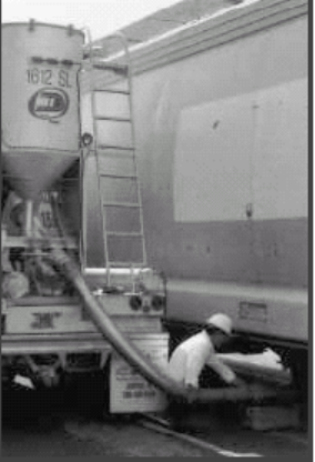
DIFFERENCES BETWEEN HOPPER TRUCK AND HOPPER CAR UNLOADING
Instead of using the vacuum system generated by the in-plant transfer system, hopper
trucks are unloaded using the air blower on the truck itself. This blower is driven by
either the tractor engine or by a remote engine (Figure 15).
Figure 15. A hopper car is unloaded
into a hopper truck for
shipment to a customer
not serviced by a rail
line. The truck’s air
blower is used to unload
the car. Note that the
conveying pipe does not
touch the ground to
prevent moisture and
contamination from
entering the system.
Courtesy of Dyna-Bulk, Inc.
Hopper truck unloading sites should be as close
to the silo as possible. Air temperature must be
kept as low as possible. An after-cooler is
recommended when conveying temperatures
exceed 100°F.
The unloading hose for hopper trucks has a
diameter of four inches, so the connection for
the transfer system should also be four inches
in diameter.
The dense-dilute phase unloading process is
recommended for unloading a hopper truck. The
objective of this process is to put as much
product into the line and use the smallest
volume of air possible to move this amount of
product. The desired velocity is just above the
velocity at which the line begins to plug. Even
though unloading systems can produce higher
air velocity, the dense-dilute phase process
takes no longer to empty the truck. The
increased amount of material moving through
the line more than compensates for the lower
velocity—and the creation of fines and
streamers is minimized through lower air
temperatures.
GAYLORD BOX HANDLING
Maintaining dust-and-dirt-free storage and production areas is the most important way to
avoid contamination of the resin that can lead to production problems.
Brush off the top of the Gaylord box before moving it to the production area.
In the production area, remove the lid from the box and take the lid away from the
production area. For dusty production areas, special covers that minimize
contamination, while allowing for unloading, are available for gaylords.
Carefully open the liner.
At this point, personnel trained in procedures that prevent contamination should do
necessary sampling.
Wipe the feed mechanism with a clean, lint-free cloth before putting it into the
Gaylord box.
Remove all empty Gaylord boxes from the production area as soon as possible.
Static charge can build up on transfer hoses. Grounding of the hose may be
necessary.

20
50-POUND BAG HANDLING
SPECIAL HANDLING FOR LYONDELLBASELL PERFORMANCE POLYMERS
ETHYLENE COPOLYMERS
WIRE AND CABLE RESINS AND COMPOUNDS
21
POLYOLEFIN POWDERS
Microthene
®
polyolefin powders for rotational molding are ground to a nominal mesh
size of 35 (nominal 500 micron). The bulk density of powders is lower than that of
pellets, but transfer systems used for pellets can be used without modification for
powders. The angle on the silo cone and hoppers should be 60 degrees or more from
the horizontal. All systems should be dust-tight and electrically grounded, as with pellet
systems.
Microthene F Microfine polyolefin powders for coatings, low profile additives and other
specialty applications can be delivered in 50-pound bags, 500-pound “Supersacks” and
500-pound boxes. These powders have an average diameter of 20 microns. All of the
recommendations for bag and box handling apply, along with the special considerations
for powders mentioned above.
While microfine powders have been classified as only a “nuisance dust,” according to
the Occupational Safety and Health Administration (OSHA), they are flammable if
ignited. It is essential that all unloading systems are grounded, as noted previously,
and all potentially spark-producing equipment is removed from the unloading area.
See Appendix 2 for safety and handling information for these powders.
Quality Assurance
Throughout this manual, we have discussed recommendations for preventing resin
contamination. Resin contamination can occur any time during the delivery, handling,
transfer and storage process. Therefore, preventing contamination must be part of
every stage in the process.
Cleanliness is the first and easiest step. All parts of the in-plant transfer system must be
clean and dry. As there are regularly scheduled downtimes for maintaining production
equipment, so should there be regularly scheduled downtimes for the inspection and
cleaning of transfer equipment. Just the simple procedure of cleaning out lines with
blowing air goes a long way toward preventing fines and streamers from developing and
contaminating future deliveries. Regular cleaning of transfer lines also finds leaks in the
system and prevents expensive resin loss. Regular inspection and cleaning of silos is
equally important.
Fines and streamers can also be reduced by:
1. Paying attention to the temperature and velocity of the transfer blowing air,
particularly with very temperature-sensitive resins.
2. Utilizing piping with specially treated interior walls.
3. By designing transfer systems that are as short in length as possible with a minimum
of bends and no tipped sections.
Each of these recommendations is discussed in greater length earlier in this manual.
22
MEETING THE GOALS OF OPERATION CLEAN SWEEP
Plastic pellets inadvertently lost at plastic production and warehouse facilities have
increased as much as 400 percent in recent years in widely separated locations. These
pellets pose a threat to fish and wildlife. The U.S. EPA has classified plastic pellets as
“significant materials.” The finding of even one pellet in storm water run-off without a
permit is now subject to federal regulatory action with the potential for substantial fines
and penalties.
Operation Clean Sweep is a plastics-industry-wide effort to prevent the accidental
release of pellets into the environment and to improve the public’s perception of our
industry. Specific recommendations for handling polyolefins to prevent resin loss into
the environment have been developed as part of the program, Operation Clean
Sweep. See http://www.opcleansweep.org/ for more information.
Those recommendations include: Enlist the aid of employees by:
Establishing written procedures focused on reducing and recovering spilled
resins.
Conducting educational awareness programs for employees to sensitize them to
the need to prevent pellet loss.
Assigning designated employees specific responsibilities for monitoring and
managing pellet retention.
Using teamwork to solve problems and build a consensus of commitment to this
task.
Establishing standard procedures and making sure the proper cleanup tools and
materials are readily available.
Establishing personnel responsibilities by making the cleanup the responsibility
of the person(s) causing the spill and insisting on immediate cleanup.
Developing a system for recovered pellets to be recycled or otherwise used in a
manner that prevents their escape into the environment.
Unloading and sampling operations are the prime sources of accidentally spilled pellets.
To repeat some points made earlier in this manual:
Pave unloading areas to facilitate the cleanup of pellets, or use a tarp or catch
tray to collect spilled pellets.
Keep unloading areas swept or vacuumed.
Anticipate the result of rain or flooding by using a collector grate and filtered
storm drain system.
When sampling from the bottom of a hopper car, be sure the outlet cap is
properly reinstalled and sealed.
When sampling from the top of a hopper car, use wide-mouthed containers or
polyethylene bags.
Thoroughly unload hopper cars and trucks and cycle the outlet valve while air is
flowing.
23
Visually confirm the compartment is empty before closing all valves and
securing outlet caps and hatches.
Purge lines before unhooking hoses; lift hoses to assist in the purging process.
Close outlets on compartment before shipping.
Externally clean bulk containers before releasing them.
Unloading problems increase the risk of spilling pellets. Clogged hoses, bridging of the
resin and surges in the unloading lines are common problems. To prevent these
problems, consider:
Eliminating transfer system air leaks and/or increasing the capacity of air
conveying systems to prevent plugging.
Adding loading nozzle interlocks to prevent transfer spills.
Including a bag house or filter-bag assembly on packaging and transfer lines.
If your resin is delivered in Gaylord boxes or 50-pound bags, you have a somewhat
different set of problems concerning pellet release because these packages are
moved around often as they are transferred from the truck to the warehouse and
finally to the production area. Here are some suggestions to avoid pellet loss:
Make sure forklift operators are trained in preventing damage to boxes and bags
as well as in cleanup procedures.
Check the length of the forks on the forklift to make sure they do not extend
beyond the pallet. If the forks do extend that far, they can cause damage to an
adjacent carton.
Inspect the product as it is unloaded.
Tape any damaged bags.
Place catch trays between the dock and tractor-trailer at the shipping/receiving
bay.
Thoroughly empty all bags and boxes: collect, handle and store empty bags and
boxes with care to prevent the loss of any remaining pellets.
Dispose of bags and boxes by recycling, incineration or in a well-managed
landfill.
LyondellBasell is a supporter of Operation Clean Sweep and more information about this
program is available at http://www.opcleansweep.org. For further suggestions and
assistance concerning resin transfer systems, handling procedures and storage,
contact your LyondellBasell polyethylene, performance products or wire and cable sales
representative, who can connect you with a specialist at LyondellBasell headquarters or a
plant location.
24
Problem
Line Plugs
Streamers
Probable Causes
Air velocity below saltation
point
Reduction in conveying air
Receiver vessel full
Material build-up
Improper line configuration
Friction-induced smearing on
pipe walls
Suggested Course of Action
Increase air volume
Ensure that inlet air filters are clean
Check for leakage through couplings,
line wear holes, valves, diverters,
crushed hoses, worn rotary feeders or
relief valves at air supply
Inspect air supply blower or fan motor,
drive belts, bearings and impellers for
damage or wear
Ensure that receiver filters are clean
Check for bridging in receiver vessel
cone
Replace or repair discharge feeder if
undersized or worn
Ensure air is cooled for tacky materi-
als, such as ethylene copolymer
resins
Eliminate sources of moisture which
will cause fines to agglomerate
Avoid using more than two consecu-
tive changes of direction
Avoid long-radius bends, horizontal to
vertical, near the pick-up point
Have interior surface of lines
roughened
Pellet Conveying Troubleshooting Guide
This guide is presented as general information only. For specific solutions to
pellet conveying problems, check with a reputable dealer concerning design
problems and possible changes.
APPENDIX 1:
25
Cool down the conveying air to
prevent softening of polymer, particu-
larly for ethylene copolymer resins
Reduce air velocity as much as
possible without going below the
salation point; the ideal pick-up
velocity is 4,500 fpm
For long transfer lines, reduce air
velocity in the last 40 feet by increas-
ing line diameter
Avoid cyclonic separation into
receiver vessel; allow material to free
fall
Install blinded tees or other specialty
elbows designed to minimize creation
of fines and streamers
Install elutriator, multi-pass separator/
respirator, scalperator or deduster for
streamer removal (generally done
only for large volumes)
Check resin supply at top of incoming
railcar, or draw sample directly from
truck, box or bags
Install wedged or baffled entry rotary
feeder so feeder pocket does not
operate full
Check for wear on vane tips of rotary
feeders and assure proper clearance
between the vane tip and the housing
Install blinded tees or other specialty
elbows designed to minimize creation
of fines and streamers
Occurrence is minimal; install an
elutriator or deduster if problem is
significant
Check incoming resin supply for
improper pellet cut
Operate at minimum possible air
velicity
Use wear-resistant materials,
particulary at bends
Pellet clipping by rotary feeder
Pellet breakage from long-radius
elbows
Pellet breakage from contact with
roughened lines
High velocity
Materials of construction
Fines
Excessive line or
bend wear
Appendix 1 (Continued)
Problem Probable Causes Suggested Course of Action
26
Appendix 1 (Continued)
Problem
Rotary feeder
wear
Material receiver
or dust collector
wear
System pressure
fluctuations
Inadequate
capacity
Resin cross-
contamination
Probable Causes
Elbow type
Piping configuration
High transfer pressure
Feeder type
Pellet momentum
Pellet feed problem
Receiver vent plugged
Relief valve leaking
System pressure
Line size
Piping configuration
Material hold-up in
transfer system
Suggested Course of Action
Use blinded tees or other specialty
elbows where needed
Minimizer number of bends in transfer
system
Operate at minimum transfer system
pressure
Use double feeder system, one as a
feeder and one as an air lock
Use high performance feeder with
tapered or replaceable blade tips
Avoid tangential entry
Install flapper plate in receiver bin and
allow pellets to impact flapper instead of
the far bin wall
Increase line diameter prior to vessel to
reduce pellet velocity
Check vent line from rotary air lock
Check for bridging at feed point or
streamer build-up at feeder discharge
Ensure that receiver vent filters are
clean
Check valve seat for plugging or wear
Avoid operation near valve set pressure
Maximize system operating pressure
Increase line size at end of system
Minimize length of flexible hoses
Minimize number of bends
Eliminate upward sloping lines
Completely purge system before
changing resin types
Avoid low-point pockets in line
configuration
Avoid use of tee-bends for tacky resins,
such as ethylene copolymer resins
27
APPENDIX 2:
Safety and Handling Information for Microthene F Microfine
Polyolefin Powders
Polyolefin dust is defined as a combustible material in the “Standard for the Prevention of Dust
Explosions in the Plastics Industry” (NFPA 654). Concentrations of polyolefin powder as low as
0.02 oz/ft
3
can burn, releasing sufficient heat to produce a self-propagating reaction that canresult
in an explosion.
CAUTION: Users of polyolefin powders should be aware that the explosive concentration is
dependent upon the particle size of the powder and upon any substance that may be added to it.
Users with questions concerning the explosive capability of polyolefin powders should evaluate
their particular composition and operations.
Since polyolefin powder can burn or explode, special care must be exercised when working with
the powder to ensure all sources of ignition, such as heat, sparks, flames and static electricity,
have been eliminated from the workplace. Specific standards have been developed by the
National Fire Protection Association (NFPA 33, NFPA 68, NFPA 70 and NFPA 654) for the proper
handling of dusts with inherent combustible/explosive properties. All operations involving the use
of polyolefin dusts should conform to these standards.
Polyolefin dust is currently classified as a nuisance material. These materials have a long history
of safe use and are not thought to produce irreversible change in lung tissue or produce
significant disease or toxic effect when exposure is kept under reasonable control. The
Occupational Safety and Health Administration (OSHA) and the American Conference of
Governmental Industrial Hygienists (ACGIH) have established permissible exposure limits of 15
and 10 mg/M
3
of air, respectively, for total nuisance dust, and 5 mg/M
3
for the respirable fraction.
Although polyolefin dust is classified as a nuisance dust, good industrial hygiene practices should
be followed to prevent avoidable exposures. In any situation, the exposure level should be kept
below the OSHA standard. Particle size distribution measurements of Microthene F powders
indicate a percentage of the particles are respirable, with approximately 30 percent to 55 percent
of the particles having a diameter of 10 microns or less. Since dusts having a diameter of 10
microns or less are theoretically capable of deposition in the lungs, exposures to these powders
should be minimized.
Minimizing exposure should be done, where possible, by designing the processing equipment to
prevent the release of dusts into the workplace. Where processing equipment cannot be
completely enclosed, the best alternative is the use of mechanical ventilation to collect and
control the dusts at the point of generation. Good housekeeping practices should be instituted to
augment dust control and to ensure that dust in the workplace is not available from accumulation
on the floor, the machinery or other structures. Vacuum cleaners of an approved type for
combustible dust applications, or fixed pipe suction systems with a remotely located exhauster
and collector should be used for cleaning.
If airborne concentrations of polyolefin dust cannot be reduced to acceptable levels, workers
should be protected by respiratory equipment. Care must be taken to select a respirator
applicable for the purpose intended. In the case of nuisance dusts, either an air-purifying
respirator with adequate filtration or an air-supplied respirator may be used, depending on the
airborne concentration of the particulates. When using respiratory protection, only NIOSH/OSHA-
approved respirators should be selected. Additionally, all aspects of the respirator program
should be thoroughly reviewed and approved by a competent health or safety professional.
28
APPENDIX 3:
Trade Names for Products of /\RQGHOO%DVHOO Chemicals, LP
Aquathene
®
Ethylene Vinylsilane Copolymer Resins
Alathon
®
High Density Polyethylene Resins
Flexathene
®
Thermoplastic Polyolefin Resins
Integrate™ Functionalized Polyolefin Resins
Microthene
®
Powdered Polyolefin Resins
Petrothene
®
Polyethylene and Polypropylene Resins
Petrothene
®
Select Polyethylene Resins
Plexar
®
Tie-Layer Resins
Ultrathene
®
Ethylene Vinyl Acetate (EVA) Copolymer Resins

2
The information in this document is, to our knowledge, true and accurate. However, since the particular uses and the
actual conditions of use of our products are beyond our control, establishing satisfactory performance of our products
for the intended application is the customer’s sole responsibility. All uses of LyondellBasell products and any written or
oral information, suggestions or technical advice from LyondellBasell are without warranty, express or implied, and are
not an inducement to use any process or product in conflict with any patent.
LyondellBasell materials are not designed or manufactured for use in implantation in the human body or in contact with
internal body fluids or tissues, LyondellBasell makes no representation, promise, express warranty or implied warranty
concerning the suitability of these materials for use in implantation in the human body or in contact with internal body
tissues or fluids.
More detailed safety and disposal information on our products is contained in the Material Safety Data Sheet (MSDS).
All users of our products are urged to retain and use the MSDS. An MSDS is automatically distributed upon purchase/
order execution. You may request an advance or replacement copy by calling our MSDS Hotline at (800) 700-0946.
Acrythene, Alathon, Flexathene, Integrate, Microthene, Petrothene, Petrothene Select, Plexar and Ultrathene are
trademarks owned or used by the LyondellBasell family of companies.
ABOUT US
LyondellBasell (NYSE: LYB) is one of the largest plastics, chemicals and refining
companies in the world. Driven by its employees around the globe, LyondellBasell
produces materials and products that are key to advancing solutions to modern
challenges like enhancing food safety through lightweight and flexible packaging,
protecting the purity of water supplies through stronger and more versatile pipes,
improving the safety, comfort and fuel efficiency of many of the cars and trucks on the
road, and ensuring the safe and effective functionality in electronics and appliances.
LyondellBasell sells products into more than 100 countries and is the world’s largest
producer of polymer compounds and the largest licensor of polyolefin technologies.
More information about LyondellBasell can be found at www.LyondellBasell.com.
5409/21/11
lyondellbasell.com
