
Revised
January 2004
OWNERS MANUAL

Record Important
Information!
Hull
HIN
Date Purchased
Dealer/Phone
Ignition Key Number
Registration Number/State
Outboard Engine
Model #
Serial #
Trolling Motor
Model #
Serial #
Trailer
Model #
Serial #
Accessory 1
Model #
Serial #
Accessory 2
Model #
Serial #
Accessory 3
Model #
Serial #
ALUMACRAFT BOAT COMPANY
315 West St. Julien Street Highway 67 North
St. Peter, Minnesota 56082-1800 Box 189
Arkadelphia, Arkansas 71923-0189
Voice: (507) 931-1050
FAX: (507) 931-9056 Voice: (870) 246-5555
FAX: (870) 246-4507
If you have a question, problem, concern or comment, visit our website at:
www.alumacraft.com.

1
INTRODUCTION
Congratulations on your choice of boats. The safety, durability and craftsmanship bred
into your Alumacraft are features designed to let you fully enjoy your boating experi-
ence. Alumacraft boats are made from the best available materials and meet or exceed
all current National Marine Manufacturers Association (NMMA) standards and U.S.
Coast Guard regulations in effect at the date of manufacture.
Before using your new Alumacraft, please take the time to carefully read this manual.
This will assist you in the proper care and operation of your boat and its equipment.
Your Alumacraft dealer is also an excellent source of boating information and service.
The dealer can set up your boat, properly adjust its trailer and mount your motor for
you. The dealer also has the knowledge and experience to answer most questions you
might have about your new Alumacraft.
IDENTIFICATION NUMBERS
Identification numbers are important! Safeguard information about your boat by
recording the Hull Identification Number (HIN) and model of your boat, and model
and serial numbers of the engine, trailer, trolling motor, and accessories on the inside
front cover of this manual. Also, store a copy of these numbers off your boat. In the
event of theft, damage, etc., submit these numbers to the local authorities, your insur-
ance agent and your dealer.
The HIN is located on the upper, starboard corner of the transom. It must be clearly
visible and may not be removed or altered in any way as regulated by federal law.

2
BOATING TERMINOLOGY
An easy way to distinguish port from starboard is to remember that “port” and “left”
both have four letters.
BOW
GUNWALE
STERN
WATERLINE
AFT
FORWARD
CONSOLE
BEAM
TRANSOM
HIN
LENGTH OVERALL (LOA)
PORT SIDE
STARBOARD
SIDE
ALUM-1
FREEBOARD
DRAFT

3
RESTRICTED AREAS
Before boating, check with Local, State and Federal authorities to identify restricted
areas. Because of the threat of terrorism, the U.S. Coast Guard has and will continue
to implement strict limits on watercraft near U.S. Navy and Coast Guard ships and
other potential targets.
PROPOSITION 65
The engine exhaust from this product contains chemicals known
to the State of California to cause cancer, birth defects or other
respiratory harm.
EMISSION CONTROL WARRANTY
INFORMATION
Your boat may be equipped with an engine that meets the strict
requirements set forth by the California Air Resources Board
(CARB). If so, the engine has a special environmental tag and
the boat has this label affixed to it. The tag and the label are
required by the California Air Resources Board (CARB). The
label has 1, 2, 3 or 4 stars. The label MUST be affixed to the
boat, if the boat is operated in the state of California and/or
bordering waters.
WARNINGWARNING

4

5
TABLE OF CONTENTS
Page
1BOATING SAFETY . . . . . . . . . . .7
Safety While Boating . . . . . . . . . . .8
Boating Regulations . . . . . . . . . . .11
Boat Safety Labels . . . . . . . . . . . .11
Boater Responsibilities . . . . . . . . .11
Emergencies . . . . . . . . . . . . . . . .15
Hazardous Conditions . . . . . . . . .16
Safe Operating Speed . . . . . . . . . .18
General Precautions . . . . . . . . . . .19
Foam Flotation . . . . . . . . . . . . . . .20
More About Boating . . . . . . . . . .20
The Environment . . . . . . . . . . . . .21
2RULES OF THE ROAD . . . . . .23
Aids to Navigation . . . . . . . . . . . .23
Right-of-Way . . . . . . . . . . . . . . . .26
3 SYSTEMS AND
COMPONENTS . . . . . . . . . . . . .29
Propellers . . . . . . . . . . . . . . . . . . .29
Electrical System . . . . . . . . . . . . .30
Console Instruments . . . . . . . . . . .30
Controls . . . . . . . . . . . . . . . . . . . .32
Safety and Functional
Features . . . . . . . . . . . . . . . . .33
Comfort and Convenience
Features . . . . . . . . . . . . . . . . .36
Fuel System . . . . . . . . . . . . . . . . .40
4 GETTING UNDERWAY . . . . . .41
Lubrication . . . . . . . . . . . . . . . . .41
Fueling . . . . . . . . . . . . . . . . . . . .41
Boarding . . . . . . . . . . . . . . . . . . .42
Pre-Operation Checklist . . . . . . . .44
Starting . . . . . . . . . . . . . . . . . . . .44
Drive Trim Angle . . . . . . . . . . . . .45
Steering . . . . . . . . . . . . . . . . . . . .46
Operation Checklist . . . . . . . . . . .46
Stopping . . . . . . . . . . . . . . . . . . .46
Anchoring . . . . . . . . . . . . . . . . . .46
Docking . . . . . . . . . . . . . . . . . . . .47
Post-Operation Checklist . . . . . . .48
5 TRAILERS . . . . . . . . . . . . . . . . .49
Choosing the Correct Trailer . . . .49
Transom Support . . . . . . . . . . . . .49
Page
Keel Support . . . . . . . . . . . . . . . .51
Winch Stand and Bow
Support . . . . . . . . . . . . . . . . .52
Boat Stabilization . . . . . . . . . . . . .52
Self Centering Keel Roller
Trailers . . . . . . . . . . . . . . . . .52
Securing the Boat to the
Trailer . . . . . . . . . . . . . . . . . .52
Trailering . . . . . . . . . . . . . . . . . . .53
Launching . . . . . . . . . . . . . . . . . .54
Loading . . . . . . . . . . . . . . . . . . . .55
6 MAINTENANCE AND
STORAGE . . . . . . . . . . . . . . . . .57
Care of Your Boat’s
Appearance . . . . . . . . . . . . . .57
Maintenance . . . . . . . . . . . . . . . .59
Attaching Accessories . . . . . . . . .62
Keeping the Boat Docked
in the Water . . . . . . . . . . . . . .62
Storage . . . . . . . . . . . . . . . . . . . .63
Reactivating the Boat After
Storage . . . . . . . . . . . . . . . . .64
7 FEATURES FOR
THE ANGLER . . . . . . . . . . . . . .65
Trolling Motor . . . . . . . . . . . . . . .65
Bow Mounted Trolling Motor
Panel . . . . . . . . . . . . . . . . . . .65
Livewells . . . . . . . . . . . . . . . . . . .66
Bow Platforms . . . . . . . . . . . . . . .68
8 WARRANTY AND SERVICE . .69
Owner’s Responsibility . . . . . . . .69
Alumacraft’s Responsibility . . . . .70
When to Contact the Dealer . . . . 70
9TROUBLESHOOTING . . . . . . .71
Troubleshooting Table . . . . . . . . .71
Marine Wiring Color Code . . . . . .76
Typical System Wiring
Diagram . . . . . . . . . . . . . . . . .77
10 GLOSSARY OF TERMS . . . . .79

6
SERVICE/MAINTENANCE LOG
HOUR
DATE READING SERVICE/REPAIRS PERFORMED

7
SECTION 1
BOATING SAFETY
Alumacraft wants your boating experience to be a safe one. This section is devoted to
general boating safety and defines the meaning of the Warning and Caution statements
used throughout this manual.
Boating accidents kill about 1,000 people each year, with many more injuries. If you
know and use safe boating practices, you will enjoy your boat more and not be a haz-
ard to yourself or others.
The Safety Alert Symbol means ATTENTION! BECOME ALERT!
YOUR SAFETY IS INVOLVED!
Indicates an imminently hazardous situation which, if not avoided, will
result in death or serious injury or substantial property damage.
Indicates a potentially hazardous situation which, if not avoided, could
result in death or serious injury or property damage.
Indicates a potentially hazardous situation which, if not avoided, may
result in minor or moderate injury or property damage.
Used without the safety alert symbol indicates a potentially hazardous
situation which, if not avoided, may result in property damage.
NOTICE
Notice indicates installation, operation, or maintenance informa-
tion which is important but not hazard-related.
The precautions listed in this manual and on your boat are not all-inclusive. If a
procedure, method, tool, or part is not specifically recommended, you must be
satisfied that it is safe for you and others, and that the boat will not be damaged or
made unsafe as a result of your decision. REMEMBER - USE COMMON SENSE
WHEN OPERATING YOUR BOAT!
CAUTION
WARNINGWARNING
DANGER
!
CAUTION

8
SAFETY WHILE BOATING
Boating-related accidents are generally caused by the operator’s failure to follow
basic safety rules or written precautions. Most accidents can be avoided if the opera-
tor is completely familiar with the boat, its operation and can recognize potentially
hazardous situations.
In addition to everyday safety, failure to observe the safety recommendations may
result in severe personal injury or death to you and/or to others. Use caution and
common sense when operating your boat. Don’t take unnecessary chances, and
remember that if you are skiing, at least three people are needed for safe towing.
Whether you use your Alumacraft boat for fishing, pleasure or skiing, these are
important things to know about safe boating.
Failure to adhere to these warnings may result in severe injury or death to you and/
or others.
• Look before you turn the boat. As a boater you are obligated to maintain
a course and speed unless it is safe to alter course and speed. Look before
you turn.
• Improper operation of the boat is extremely dangerous. Operators must
read and understand all operating manuals supplied with the boat before
operation.
• On-board equipment must always conform to the governing federal, state
and local regulations.
• DO NOT operate the boat while under the influence of alcohol or other
drugs.
• DO NOT stand or allow passengers to stand in the boat, or sit on the tran-
som, seat backs, engine cover or sides of the boat while the engine is run-
ning. You or others may be thrown from the boat.
• DO NOT allow any type of spark or open flame on board. It may result in
fire or explosion.
• DO NOT leave children in the boat without adult supervision.
• DO NOT sit in front of the operator to avoid obstructing the operator’s
view.
• DO NOT dive from the boat without being absolutely sure of the depth of
the water, otherwise severe injury or death may occur from striking the
bottom or submerged objects.
• DO NOT swim near the boat when the engine is running. Being in
NEUTRAL is not enough, the propeller may still be turning and carbon
monoxide may be present.
• DO NOT replace your boat’s marine parts with automotive parts.
• DO NOT remove or modify any components of the fuel system except for
maintenance by qualified personnel. Tampering with fuel components
may cause a hazardous condition.
• DO NOT wrap ski lines or mooring lines around any body part which may
become entangled in the line if you fall overboard and the boat is moving.
• Keep track of ski lines and dock lines so they do not become entangled in
the propeller.
• Be sure to securely attach the engine Emergency Stop switch lanyard to a
part of your clothing, such as a belt loop, when operating the boat.

9
• Be sure to keep a watch for other boats, swimmers and obstructions in the
water. Stay away from other boats and personal watercraft.
• Be sure to have an experienced operator at the helm and always have at
least three people present for safe towing – one to drive, one to observe and
one to ski or ride.
• Seek shelter from open water if there is threat of lightning.
• Operate slowly in congested areas such as marinas and mooring areas.
• The bow may be slippery, do not go forward while the engine is running.
• When you leave the boat take the keys with you. This will keep untrained
and unauthorized persons from operating the boat.
• Engine exhaust contains carbon monoxide.
• DO NOT operate the engine in a confined space.
• DO NOT go under the boat cover with the engine running or shortly after
the engine has been running.
• DO NOT use boarding platform with the engine running.
• DO NOT “teak surf.”
• Allow adequate ventilation with fresh air before entering.
• Slow down when crossing waves or wake in order to minimize the impact
on passengers and the boat.
Teak Surfing
READ, UNDERSTAND and be FAMILIAR with the information contained on
warning labels and adhere to the boat operation practices described on them. The
United States Coast Guard issued a SAFETY ALERT on August 28, 2001 that cov-
ers some of the issues of improper use of the boarding platform. The SAFETY
ALERT and portions of the accompanying information follow:
Every year tragic deaths occur from the negligence of unsafe boating and dangerous
activities. Experts say, "many of these deaths may have been caused by an invisible
hazard, carbon monoxide poisoning." Taking the risk of swimming under a boarding
platform when the engine is running, skiing within 20 feet (6.1 meters), "teak surf-
ing" or "dragging" behind a moving boat can be fatal.
DO NOT use the boarding platform or ladder for any other purpose than boarding the
boat or preparation of entering the water, and DO NOT use the boarding platform or
ladder when the engine is running.
SAFETY ALERT From August 28, 2001:
The United States Coast Guard advised boaters not to “Teak Surf.” Recent boating
fatalities revealed that carbon monoxide (CO) emitted from a vessel’s exhaust result-
ed in CO poisoning and the death of at least six teak surfers. “Teak Surfing” places
the individual in position directly exposed to the CO in the engine’s exhaust. This
may result in a loss of coherent responses and even death. In addition, “Teak Surfing”
dangerously exposes the individual to a possible propeller injury, and since it is done
without a life jacket (PFD), it significantly increases the probability of drowning.
Therefore, the Coast Guard stresses, “Teak Surfing” is a very dangerous activity and
advises boaters not to participate in it.
Carbon monoxide is one of the most dangerous gases. It impairs and can often lead
to death. It is important to the Coast Guard that it should be avoided in every
circumstance.

10
General Water Sport Precautions
• DO NOT ski in shallow water, close to shore or in water where you do
not know the depth or what is beneath the surface.
• DO NOT put your arm, head, or any other part of your body through
the handle-bridle of the ski line nor wrap the line around any part of the
body at any time.
• DO NOT ski at night or directly in front of other boats.
• DO NOT jump from a boat that is moving at any speed, nor enter or exit
the water when the engine is running (RUN).
• DO NOT approach the boat if the engine is running.
• DO NOT ski near swimming areas, beaches or personal watercraft.
• DO NOT follow directly behind another boat or skier without leaving an
adequate safe distance.
• DO NOT "back up" to anyone in the water.
• DO NOT ski with multiple skiers with different length ropes.
• DO NOT ski in limited visibility conditions.
• DO NOT approach the rear of the boat while the engine is running.

11
BOATING REGULATIONS
The U.S. Coast Guard is the authority of the waterways
and are there to help the boating public. State boating
regulations are enforced by State authorities. You are
subject to marine traffic laws and “Rules of the Road”
for both federal and state waterways. It is mandatory to
stop, if signaled to do so by enforcement officers, and
permit your boat to be boarded if asked. In addition,
always take note of the specific lake rules posted at the
launch access sites on the body of water you wish to
navigate.
There are many pamphlets, prepared by the Coast
Guard, available to you which explain rules of the road,
international and inland regulations, and much more
than is presented in this manual. For more information,
contact your local U.S. Coast Guard Unit or call the
U.S. Coast Guard Boating Customer Information Line
at 1-800-368-5647. This phone number also appears on
a label affixed to your boat.
BOAT SAFETY LABELS
The following safety labels were affixed to your boat at the time of manufacture and
must remain legible. Should one of them be missing or become damaged, contact your
dealer for immediate replacement.
BOATER RESPONSIBILITIES
Registration
The U.S. Coast Guard requires that all power boats operated on the navigable waters
of the United States be registered in the state of main use. Many states also require reg-
istration in that state whenever boating on waters within their state boundary. Always
contact your state boating authorities and neighboring states for information on boat
and trailer registration. Your dealer may be able to supply you with the appropriate
forms.
Label Color Location
Emergency White Console Models:
Shut-off Lanyard and Orange Tiller Models:
Center Seat White Console Models:
Warning Label and Red Tiller Models:
Capacity Label Silver Console Models: Mounted on dash or port side
(see Capacity in Section 4) and Yellow opposite console, visible to operator.
Boatman’s Check List Orange Tiller Models: Mounted inside boat on port side;
or Blue visible to operator.
Fuel Vapor Warning Label Yellow Underside of all non-ventilated Compartments.
Leaking Fuel Yellow Located in splashwell area on underside of lid,
or on face of flotation cover.
KC-0459

12
Insurance
You must get insurance before operating your new boat. Loss by fire, theft or other
causes, and liability protection against accidents make such coverage a must for
responsible boaters. The boat owner is legally responsible for any damage or injury
caused when he or someone else operating the boat is involved in an accident. Many
states have laws requiring minimum insurance needs. Your insurance agent will be
able to supply you with more information.
Education
This manual is not intended to be a complete training guide on all aspects of safe boat-
ing and proper boat operation. Many states require operators under the age of 18 to be
licensed in small boat operation and offer courses for training and certification.
Alumacraft strongly recommends that prior to using your boat, you attend a boating
safety course offered by the U.S. Coast Guard, U.S. Coast Guard Auxiliary or U.S.
Power Squadron in your area. You can call the U.S. Coast Guard Boating Education
Hotline at 1-800-336-2628 for further information.
Some states require youths of a certain age to complete a boating safety course before
operating any watercraft. Many others require operators under the age of 18 to be
licensed in small boat operation.
Minors must be supervised by an adult whenever operating a boat. Many states have
laws regarding the minimum age and licensing requirements of minors. Be sure to
contact the state boating authorities for information.
Required Safety Equipment
The U.S. Coast Guard requires that boats be equipped with safety gear on board at all
times. Alumacraft boats are Class A (16' and under) or Class 1 (16' to 26') as classified
by the U.S. Coast Guard. Required equipment for inland waters includes:
Fire Extinguisher
Most Alumacraft boats require a Class B fire extinguisher. It must be a 2 lb. (0.9 kg)
dry chemical, 1.25 lb. (0.6 kg) foam unit or 4 lb. (1.8 kg) CO
2
extinguisher mounted
in a readily accessible location.
Sound Signaling Device
Most Alumacraft boats have a horn. If you do not have a horn, you will need a whis-
tle, bell or an aerosol sound device.
Visual Signaling Device
If you will be on the Great Lakes or coastal waters with your Alumacraft, a visual sig-
nal device is required. During daylight hours, this can be a standard orange distress
flag. For night use, Coast Guard approved flares are required. Check with your
Alumacraft dealer or the Coast Guard for specific information concerning these
devices.
Navigation Lights
Navigation lights are required if operating your Alumacraft between the hours from
sundown to sunup.
Personal Flotation Device (PFD)
PFDs include Type I, II, III, IV, and V flotation devices. All boats, regardless of size
must carry a Type I, II, III, or V wearable PFD for each person on board or water ski-
ing. All boats exceeding 16 ft. (4.9 m) in length must also be equipped with a Type IV
throwable device.

13
PFDs are intended to help save lives. You and your passengers should wear a PFD
whenever boating. It is especially important that children and non-swimmers wear a
PFD at all times. Make certain all passengers know how to put on and properly adjust
their PFDs. Also, selecting the proper type of PFD for your kind of outing helps ensure
your time on the water can be the safest possible. There are four types of PFDs to wear
and one type used for throwing in emergency situations.
Type I: Most buoyant PFD and effective on all waters,
especially open, rough water.
Type II: Good for calm water near shore on most
inland waters where quick rescue is likely.
Type III: Good for most inland water applications
where quick rescue is likely. Come in various
styles and some are designed for watersport
activities.
Type IV: Intended for heavy traffic inland waters where
help is always available. Designed to be
thrown to a person in the water and should
never be worn.
Type V: Inflatable design for special use activities and
may be used instead of a Type I, II, or III PFD
if used in accordance with the approval
conditions on the label and if worn when the
boat is underway. Some Type V PFDs provide
increased protection against hypothermia.
NOTICE
• If a Type V PFD is to be counted toward the
minimum carriage requirements, it must be
worn.
• Special PFDs are available for skiing and other
watersports. These PFDs are constructed with
materials suitable for high impact falls.
Keep the following PFD points in mind:
• Set an example and wear your PFD. Require your
passengers to wear them also.
• Make sure the PFD fits properly; this is especially
important for children and non-swimmers.
• At the beginning of each season, check PFDs for
damage and test for proper flotation.
TYPE I
TYPE II
TYPE III
TYPE IV
TYPE V HYBRID PFD
MUST BE WORN
WHEN UNDERWAY
C

14
Recommended Equipment
As a precaution, a good boater will avoid potential problems on an outing by having
additional equipment on board. Normally, this equipment is dependent on the body of
water and the length of your trip. Your dealer can assist you:
• First aid kit and manual
• Anchor with at least 75 ft (23 m) of line
• Mooring lines and fenders
• Bailing device (bucket, hand pump, etc.)
• Combination oar/boat hook
• Day/night visual distress signal
• Lubricant
•Tool kit
• Spare propeller, nut and washer
• Spare fuses
• Local charts and compass
•Waterproof flashlight
• Portable AM/FM radio with weather band
• Spare flashlight and radio batteries
• Sunglasses and sun block
• Cellular phone
15
EMERGENCIES
Reporting
When an accident occurs, the operator of the boat is responsible for filing a report with
the appropriate authorities. Generally, reports are necessary for accidents involving
loss of life, injury or damage over $200. Ask your insurance agent for specific details.
Rendering Assistance
The United States Code, Title 46 states, The owner or operator of a vessel is required
by law to render assistance to any individual or vessel in distress, so long as his ves-
sel is not endangered in the process. The 1971 Boating Safety Act grants protection to
a “Good Samaritan” boater offering good faith assistance, and absolves a boater from
any civil liability arising from rendering assistance.
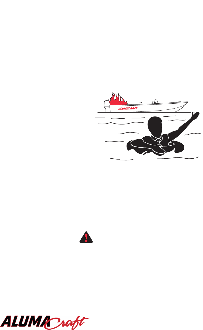
Fires
Most fires are the result of gasoline
and oil accumulating in the bilge
from careless fueling practices
combined with the careless use of
smoking materials. If a fire should
start, aim the fire extinguisher at the
base of the flames using a sweeping
motion. If the fire does not go out,
or if there is a chance of explosion,
get out immediately and swim at
least 25 yd. (22.9 m) upwind from
the boat and use the visual distress
signals to get assistance.
On board fires involving the fuel system usually result in either an explosion that com-
pletely destroys the boat, or the boat burning to the waterline and self extinguishing.
Deciding on abandoning the boat or staying to fight the fire is difficult and depends on
many factors. Try to formulate a fire plan in advance so decisions can be made with-
out hesitation in the event of a fire.
The best way to avoid fires is to refuel safely, keep ignited smoking materials away
from flammables, and maintain your electrical system in its original condition.
Gasoline will float on the water and can burn. If the boat is aban-
doned, swim far enough upwind to avoid fuel that may spread
over the surface of the water to avoid serious injury.
Capsizing and Swamping
Aboat can become capsized or swamped when least expected by large waves or wakes
coming over the bow, gunwales or stern, or by hitting something that damages the hull.
Like fires, try to formulate a plan well in advance. The best way to avoid these acci-
dents is to turn into the waves with the boat properly trimmed and avoid collisions with
stationary objects in the water.
WARNINGWARNING
KC-0162.
1

16
Always anchor from the bow and never anchor from the stern in
strong currents. A small current will make the boat unsteady...a
strong current can pull a boat anchored by the stern under water
and keep it there.
If your boat capsizes or becomes completely swamped, keep in mind the following
guidelines:
• Stay away from the propeller and try to turn off the engine to prevent injury and
damage.
• If others were on board, try to
locate them and make sure they
are conscious and can swim.
• Stay with the boat. Your
Alumacraft is equipped with level
flotation and will not sink.
• Do not try to swim to shore unless
you are very close to land. It’s
usually further than it looks.
• If the boat is inverted, try to climb
onto the bottom of the hull and
get assistance.
If you’ve struck something and your boat begins to take on water:
•Try to plug the leaks with cloth or any available materials.
• Run the bilge pump and bale with buckets.
• Immediately head for the nearest port or beach the boat on the nearest shore.
• If the boat eventually swamps, stay with it. It will float.
HAZARDOUS CONDITIONS
Every waterway poses hazards that you should avoid; shallow water, tree stumps,
rocks, etc. Ask local boaters for information and consult a marine chart when boating
on unfamiliar waters.
Weather
Getting caught in severe weather
on a large body of water is danger-
ous. If navigating on such waters,
your boat should be equipped with
communications gear, a marine
VHF-FM and/or HF transceiver as
applicable to your operating area.
Always check with the local
weather stations, the U.S. Coast
Guard, or Weather Service broad-
casts for the latest conditions before
venturing out.
WARNINGWARNING
KC-0170
KC-0212.2
OK
!

17
While on the water, the best way to receive timely weather information is by radio.
NOAA Weather Radio (NWR), operated by the National Weather Service, provides
continuous weather programming for all U.S. waters at 162.55 or 162.40 Megahertz
on your FM radio. Always monitor your communications equipment while boating so
you have adequate time to seek port in the event of a storm.
If you do get trapped in bad weather, turn into the waves and proceed slowly. Keep all
passengers low, near the center of the boat and make sure everyone is wearing their
PFD. If you must move in the same direction of the waves to get home, try to keep on
top of each wave and maintain the same speed as the wave.
Dam Spillways
The water around a dam spillway is a hazardous area. It is subject to rapid changes and
must be avoided.
Weeds
Weeds are generally a threat to your boat’s engine. Weeds on the propeller may
cause the engine to vibrate and can restrict water intake, causing overheating of the
engine. If you run into heavy weeds, stop the engine and make sure the propeller is
completely stopped. Clear the propeller and water intake completely of weeds
before proceeding.
Weeds can sometimes be removed by shifting to neutral, pausing a moment, then shift-
ing to reverse to unwind the weeds from the propeller.
Shallow Water Operation
Operating in shallow water presents a number of hazards. Water of any depth may con-
tain stump fields, sand bars, rocks, or other unmarked underwater hazards. If the
engine strikes an underwater hazard, check for boat and engine damage. If the engine
vibrates excessively after striking an underwater obstruction, it may indicate a dam-
aged propeller.
Carbon Monoxide Poisoning
Carbon monoxide (CO) is a colorless and odorless gas that is extremely dangerous.
Even the best boat design and construction may not prevent hazardous levels of CO
from accumulating. You must provide adequate air flow ventilation through the boat
when operating the boat with the convertible top and/or side curtains in place. You
should also pay attention to the effects caused by other vessels moored or anchored
next to your boat and the effect of your exhaust on other boaters.
Sources of carbon monoxide include:
• Blockage of boat exhausts by obstruction.
• Exhausts traveling along obstruction.
• Operating at slow speed or while dead in the water.
• Operating with high bow angle.
• Exhausts from other vessels in confined areas.
• Operating with canvas tops and side curtains in place without ventilation.
To reduce CO accumulation, always ventilate the boat interior by opening the deck
hatches, windows and/or canvas to allow for air flow through the boat. If you suspect
someone is a victim of CO poisoning, have them breathe deeply and seek immediate
medical attention.

18
EXTREME HAZARD - Carbon monoxide gas (CO) is colorless,
odorless and extremely dangerous. All engines and fuel burning
appliances produce CO as exhaust. Direct and prolonged expo-
sure to CO will cause BRAIN DAMAGE or DEATH. Signs of
exposure to CO include nausea, dizziness and drowsiness.
Warning Markers
It is a good idea to ask local boaters and authorities if
there are hazardous areas and how they are marked.
Boaters must also recognize the flag designs which
indicate divers are present and stay well clear of the
area. Watch for swimmers, down water skiers and
restricted areas. Swim areas and many underwater haz-
ards may not be marked, especially on rural waters with
little watersport activity. Always stay alert and watch
for others in congested waters.
Distress flags indicate a fellow boater
is in need of assistance. Navigation
markers serve as a means of identify-
ing navigable routes, and indicate
water hazards.
SAFE OPERATING SPEED
Maneuvering speed is the maximum speed at which you can make sudden turns with-
out risking loss of boat control. This speed depends on weather and water conditions,
and how the boat handles. Like automobiles, each boat handles a little differently and
the method by which the boat is steered, whether tiller controlled or steered at a con-
sole will make a difference. There are also minimum safe speeds for certain condi-
tions. In high winds, it may be necessary increase speed to maintain headway or to
keep the bow of the boat up to prevent waves from breaking over it. Careful experi-
mentation with your boat in various conditions will help you learn the safe operating
speed for your particular boat.
KC-0942
DISTRESS
USED BY
RECREATIONAL
DIVERS -
INDICATES
DIVER'S
POSITION
WORLDWIDE
VESSELS
ENGAGED IN
DIVING
OPERATIONS -
DOES NOT
INDICATE
DIVER'S
POSITION
KC-0372.1
RED
BLUE
DIVERS FLAG
ALPHA FLAG
KC-0260.1

19
GENERAL PRECAUTIONS
As operator of your Alumacraft boat, your safety and that of your passengers and other
boaters is your responsibility. Please use the following general precautions each time
you use your boat:
• Provide and use all required safety equipment.
• Make sure all children and nonswimming passengers wear their PFDs and all other
passengers have ready access to them.
• Make sure all persons are properly seated before moving the boat.
• Make sure you load passengers and gear safely, distributing all loads evenly.
• Know the maximum weight capacity and horsepower rating for your boat, and do
not exceed these limits.
• Refuel safely as described in Section 4 - Getting Underway.
• If you are on “Big Water” be sure someone on shore knows where you plan to be.
• Do not risk boating in storms or when storms are forecast.
• Always attach the emergency shut-off lanyard to the operator before starting the
gasoline engine.
• Always stay alert when underway and keep one hand on the steering mechanism
and one hand on the throttle. Never let go of the steering control.
• Know the nautical rules as described in Section 2 - Rules of the Road in this man-
ual.
• Learn to anchor and dock properly as described in Section 4 - Getting Underway.
• At night, use navigation lights and travel at slower speeds.
• Never operate your boat while under the influence of alcohol or other drugs.
Never operate or allow another person to operate the boat while
under the influence of drugs or alcohol. Fifty percent of all boat-
ing fatalities involve alcohol. Operation while under the influence
of such substances is a violation of Federal law.
WARNINGWARNING

20
FOAM FLOTATION
Boats built after July 31, 1973 are required to meet applicable U.S. Coast Guard
standards for flotation. It becomes necessary to remove foam flotation material for
repairs or modification. It is important that the flotation be re-installed in its original
position.
When replacing flotation foam, use only gasoline resistant foam of
equivalent density and quantity to that originally provided. Use of
insufficient or sub-standard replacement foam could be dangerous.
MORE ABOUT BOATING
The more you learn about boating, the more fun you will have and the safer you will
be on your new Alumacraft. The following is a listing of some of the agencies and
organizations that provide free boating classes and information. Use your local tele-
phone directory for their telephone numbers and addresses.
• American Red Cross
• U.S. Coat Guard Auxiliary
• National Fishing and Wildlife Foundation
• U.S. Power Squadrons
• State Boating Offices
• Sport Fishing Institute
U.S. nautical charts can be purchased throughout the country at Government Printing
Office stores and through agents. To learn where you can buy these, write for a chart
catalog: National Oceanic and Atmospheric Administration, National Ocean Survey,
Rockville, MD 20852.
Some of the federal agencies that publish recreational maps include the U.S. Army
Corps of Engineers, the U.S. Forest Service, the National Park Service and the
Tennessee Valley Authority. In addition, you can get a free listing all state boating
agencies by writing: National Marine Manufacturers Association, 401 N. Michigan
Ave., Chicago, IL 60611.
WARNINGWARNING

21
THE ENVIRONMENT
As a boater, you already appreciate nature’s beauty and the peace of the great outdoors.
It is a boater’s responsibility to protect the natural environment by keeping waterways
clean.
Don’t put anything in the water you wouldn’t want to eat or drink!
Conserve Fishery Resources
There is a tremendous drain on our fishery resources. Over-fishing and pollution have
strained the fish population. Do your part by keeping only what you will eat by
practicing catch-and-release.
Foreign Species
If you trailer your boat from lake to lake, you may unknowingly introduce a foreign
aquatic species from one lake to the next. Thoroughly clean the boat below the water
line, remove all weeds and algae, and drain the bilge and livewells before launching
the boat in a new body of water.
Fuel and Oil Spillage
The spilling of fuel or oil into our waterways contaminates the environment and is
dangerous to wildlife. Never discharge or dispose fuel or oil into the water; it is
prohibited and you could be fined. There are two common, accidental types of
discharge:
• Overfilling the fuel tank
• Pumping contaminated bilge water
Fumes from rags can collect in bilge and be extremely hazardous.
Never store rags used to wipe up fuel or solvent spills in the boat.
Dispose of rags properly ashore.
Discharge and Disposal of Waste
Waste means all forms of garbage, plastics, recyclables, food, wood, detergents,
sewerage and even fish parts in certain waters - in short, nearly everything. We
recommend you bring back everything you take out with you for proper disposal
ashore.
If you have a marine sanitation device (head or marine toilet) installed, use an
approved pump-out facility at your marina. Many areas prohibit the discharge of sew-
erage overboard or even an operable overboard waste discharge.
WARNINGWARNING

22
Excessive Noise
Noise means engine noise, radio noise or even yelling. Many bodies of water have
adopted noise limits. Don’t use thru-transom exhaust unless you’re well off shore.
Music and loud conversation can carry a considerable distance on water, especially at
night.
Wake and Wash
Be alert for NO WAKE zones. You may be responsible for any damage or injury
caused by your wake/wash. Prior to entering a NO WAKE zone, come off plane to the
slowest steerable speed.
Exhaust Emissions
Increased exhaust (hydrocarbon) emissions pollute our water and air. Keep your
engine tuned and boat hull clean for peak performance. Consult your dealer and engine
manual for information.
Paints
If your boat is kept in water where marine growth is a problem, the use of anti-
fouling paint may reduce the growth rate. Be aware of environmental regulations that
may govern your paint choice. Contact your local boating authorities for information.
Cleaning Agents
Household cleaners should be used sparingly and not discharged into waterways.
Never mix cleaners and be sure to use plenty of ventilation in enclosed areas. DO NOT
use products which contain phosphates, chlorine, solvents, non-biodegradable or
petroleum based products. Citrus based cleaners are excellent for marine cleaning
purposes and are safe for you and the environment. Refer to MAINTENANCE for
more information.

23
SECTION 2
RULES OF THE ROAD
NOTICE
The nautical rules of the road must be followed to prevent colli-
sions between vessels. Like traffic laws for automobiles, the oper-
ator is legally required to follow the rules.
AIDS TO NAVIGATION
The following information outlines only the most basic of the nautical rules of the
road. For more information, contact your local U.S. Coast Guard Auxiliary.
Learn to recognize the different buoys and day markers; they are the signposts of the
waterway. There are two primary marking systems in use in the U.S.; the Uniform
State Waterway Marking System (USWMS) used on inland waters and maintained by
each state, and the Federal Waterways Marking System (FWMS) used on coastal
waters and rivers and maintained by the U.S. Coast Guard (USCG). In addition, the
FWMS has two modified systems; Western River Buoyage, and Intracoastal
Waterway Buoyage. Be sure to check with local authorities on the buoyage system in
use.
The type of hazard/warning buoys and markers depend on the area of jurisdiction.
Check with local boating authorities.
USWMS System
In the USWMS Lateral System, well defined channels are marked with red and black
buoys. Lateral means the sides of the channel are marked and the boat should pass
between them.
The USWMS Cardinal System is used when there is no well defined channel or where
an obstruction may be approached from more than one direction. With the cardinal
system:
• Pass north or east of BLACK-TOPPED WHITE buoy.
• Pass south or west of RED-TOPPED WHITE buoy.
• RED and WHITE VERTICALLY STRIPED buoy indicates boat should pass out-
side of the buoy (away from shore).

24
Uniform State Regulatory Markers
USWMS regulatory markers are white with international orange geometric shapes;
you must obey regulatory markers.
CONTROLLED
AREA
DANGER
BOATS
KEEP OUT
INFORMATION
DO NOT PASS
BETWEEN SHORE
AND BUOY
SPECIAL
PURPOSE
KC-0411.3
NAVIGATE TO
STARBOARD
FACING UPSTREAM
NAVIGATE TO
PORT FACING
UPSTREAM
NAVIGATE TO
SOUTH OR WEST
NAVIGATE TO
NORTH OR EAST
MID-CHANNEL
KC-0411.2
25
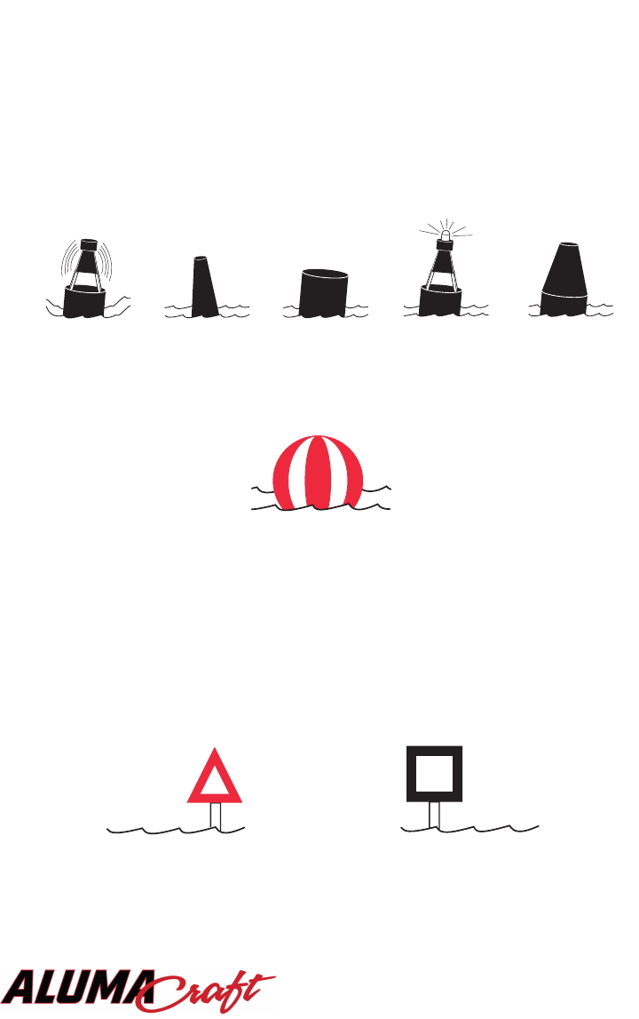
FWMS System
The FWMS Lateral System is for use on navigable waters except Western Rivers and
Intracoastal Waterways.
The markings on these buoys are oriented from the perspective of being entered from
seaward (the boater is going towards the port). This means that red buoys are passed
on the starboard (right) side when proceeding from open water into port, and black
buoys are to port (left) side.
The right side (starboard) of the channel is marked with RED, even numbered buoys.
The left (port) side of the channel is marked with GREEN, odd numbered buoys.
The middle of the channel is marked with RED and WHITE vertically striped buoys;
pass close to these buoys.
Obstructions, channel junctions, etc. are marked with RED and GREEN horizontally
striped buoys.
ARED band at the top means the preferred channel is to the left of the buoy; a GREEN
top band means the preferred channel is to the right of the buoy.
Day markers are colored and numbered the same as buoys. RED, triangular day mark-
ers with even numbers mark the starboard side of the channel. GREEN, square day
markers with odd numbers mark the port side of the channel.
Lights, bells and horns are used on buoys for night or poor visibility conditions.
UNLIGHTED
BELL BUOY
LIGHTED BUOY
CAN BUOY
SPAR BUOY
NUN BUOY
KC-0420
STARBOARD
DAY
MARKER
KC-0440
KC-0440
PORT
DAY
MARKER
SPHERICAL SAFE
WATER MARKER
KC-0430

26
RIGHT-OF-WAY
NOTICE
In general, boats with less maneuverability or boats that are not
powered, or are powered by sail have the have right-of-way over
more agile craft. Likewise smaller boats should give way also. You
must stay clear of the vessel with right-of-way and pass to his
stern.
Privileged Boats
Privileged boats have right-of-way and can hold course and speed. Sailboats and boats
paddled or rowed have the right-of-way over motor boats. Sailboats under power are
considered motorboats. Small pleasure craft must yield to large commercial boats in
narrow channels.
Burdened Boats
The burdened boat is the boat that must make whatever adjustments to course and
speed necessary to keep out of the way of the privileged boat.
Crossing Situation
In crossing situations, the boat to the right from the 12 o’clock to the 4 o’clock posi-
tion has the right-of-way. It must hold course and speed. The burdened boat keeps
clear and passes behind the privileged boat. Boats going up and down a river have the
privilege over boats crossing the river.
K
C
-
0
474.1
BURDENED
VESSEL
DANGER ZONE
PRIVILEGED
VESSEL
12 O'CLOCK
4 O'CLOCK

27
Meeting Head-On
Neither boat has the right-of-way in this situation. Both boats should decrease speed,
should turn to the right, and pass port-to-port. However, if both boats are on the left
side of a channel, each vessel should sound two short horn blasts and pass starboard
to starboard.
KC-0584
PASSING
PORT TO
PORT
MEETING
HEAD TO
HEAD
PASSING
STARBOARD TO
STARBOARD
HONK
HONK
HONK
HONK

28
Overtaking
In overtaking situations, the boat being passed has the right-of-way, and the passing
boat is required to stay clear.
The General Prudential Rule
The general prudential rule regarding right-of-way is that if a collision appears
unavoidable, neither boat has right-of-way. Both boats must act to avoid collision.
Night Running
Boats operating between sunset and sunrise (hours vary by state) must use naviga-
tional lights. Nighttime operation, especially during bad weather or fog can be dan-
gerous. All Rules of Road apply at night, but it is best to slow down and stay clear of
all boats, regardless of who has right-of-way. Protect your night vision by avoiding
bright lights and have a passenger, if possible, help keep watch for other boats, water
hazards, and aids to navigation. The size, speed and direction of other vessels are
determined at night from the running lights. A green light indicates the starboard side
of a boat and a red light indicates the port side. Generally if you see a green light, you
have the right-of-way; if you see a red light, give way to the vessel. A spotlight or
flashlight is recommended to help identify buoys and hazards such as stumps and
rocks.
KC-0604
PRIVILEGED
VESSEL BEING
OVERTAKEN
BURDENED
VESSEL
OVERTAKING
29
SECTION 3
SYSTEMS AND
COMPONENTS
NOTICE
Some problems with specific boat controls and instruments are
addressed in Section 9 - Troubleshooting.
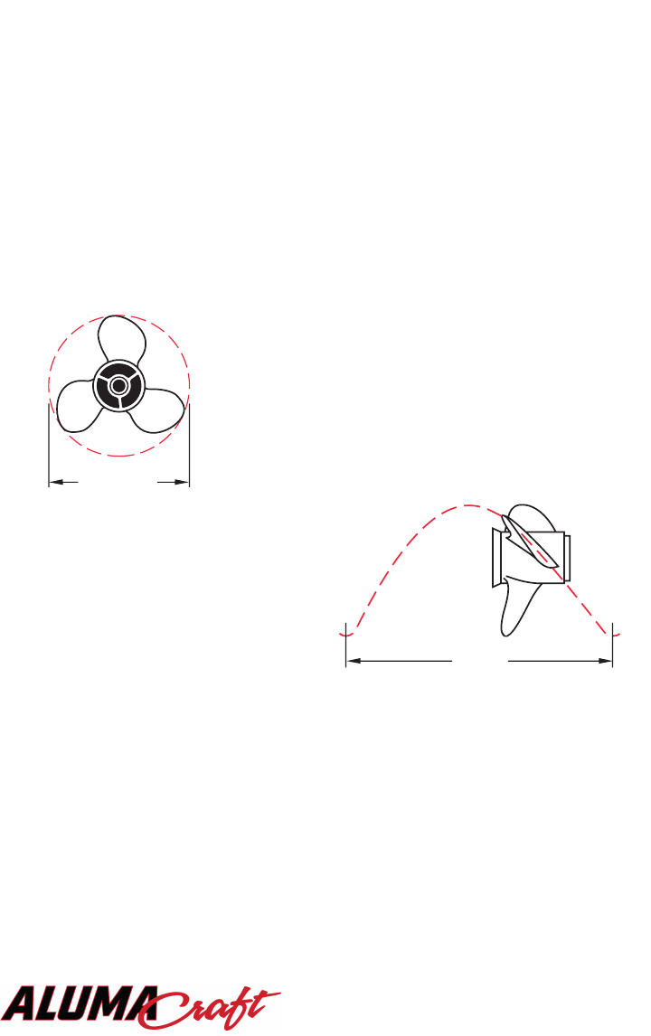
PROPELLERS
The propeller converts the engine’s power into the thrust need-
ed to propel the boat. Care and selection of your propeller is
very important to proper boat operation. Propellers are identi-
fied by two numbers, such as 13 x 19, and a material identifi-
cation, such as aluminum or stainless steel. In the number
sequence, the first number is the diameter of the propeller and
the second is the pitch.
Pitch is the angle of the blades
expressed in the theoretical distance a
propeller travels in each revolution. In
the above example, the pitch is 19, or
each revolution of the propeller pushes
the boat 19 in. (48.3 cm) through the
water.
Keep these guidelines in mind when
selecting a propeller:
• There are many different propeller designs for specific operating characteristics,
including the number of blades, relief holes, cupping, etc. Do not attempt to change
propellers until after you have a chance to determine your average load and indi-
vidual requirements. Your dealer is best qualified to help you select a propeller.
• Engine RPM must be within the recommended operating range. Refer to the engine
operator’s manual, and see Tachometer, found later in this section.
• Higher propeller pitch reduces: RPM power, acceleration, engine noise, and usual-
ly improves fuel economy and top speed.
• Lower propeller pitch increases: RPM power, acceleration, engine noise, reduces
fuel economy and top speed.
KC-1581.1
PITCH
(ONE REVOLUTION)
DIAMETER
KC-1580.1

30
Before installing or removing the propeller:
• Put the remote control in the NEUTRAL position.
• Put the main switch in the off position and remove the key.
A smaller pitch propeller should be selected for water skiing or for heavy loads. A
smaller pitch propeller will develop more thrust for faster planing. A higher pitch pro-
peller should be selected if full throttle RPM exceeds the maximum recommended
range. See Tachometer, discussed later in this section.
DO NOT use your hand to hold the propeller when loosening the
nut. You could be seriously injured. Put a wood block between the
cavitation plate and the propeller blade to prevent the propeller
from turning.
ELECTRICAL SYSTEM
Your Alumacraft is equipped with a 12 volt (V), negative ground DC electrical sys-
tem. In the 12V setup, a single 12V battery supplies all electrical power. The red pos-
itive wire is hot and the black negative wire is ground. With the addition of an option-
al trolling motor battery, one battery is used for engine cranking and systems power,
and the other exclusively for the trolling motor.
The cranking or starting battery is recharged by the alternator when the engine is oper-
ating. The batteries supply power to the electrical system through the fuse panel. The
trolling motor batteries are not connected in any way to the cranking battery. Trolling
motor batteries must be recharged with a battery charger on shore as described in
Section 6 - Maintenance and Storage.
CONSOLE INSTRUMENTS
Speedometer
Your boat’s speedometer registers forward boat
speed in miles per hour (mph) and kilometers
per hour (km/h). Generally it will not register
under 10 mph (16 km/h), and at maximum
speed there may be a slight speed fluctuation
indicated. These are normal functions since
most marine speedometers operate with water
pressure.
The speedometer is useful to find the best trim
setting and can be used in conjunction with the
tachometer to determine the best propeller pitch
for your motor.
WARNINGWARNING
WARNINGWARNING
15
20
25
35
40
50
45
MPH
KPH
20
30
40
50
60
70
80
30
KC-0710

31
Tachometer
This gauge registers motor speed in revolutions per minute
(RPM). Use this gauge to keep the motor within proper
operating range. Knowing the RPM at which your motor is
running is also useful for determining the proper trim set-
ting, and for choosing the correct propeller, when used in
conjunction with the speedometer.
To determine if you have the correct propeller by using
your tachometer as a guide, first consult your engine
owner’s manual for your outboard’s optimum RPM range
(e.g., 4800 to 5500 RPM). This is the acceptable RPM
range with the outboard operating at wide open throttle. If
the engine is operating below this range, it is not delivering
its best performance. Operation of the engine above this
range could result in serious engine damage. Your dealer
can assist you in selecting a propeller that is safe for your
outboard and matches your specific performance needs.
If your motor is equipped with a power trim and tilt unit,
you can also fine tune the best motor trim range by using
the tachometer and speedometer. Once on plane and at a
steady throttle, trim the motor up slowly until the maxi-
mum speed is reached for that throttle setting. If you trim
up too far, the tachometer speed will increase and the speed
will decrease.
Voltmeter
The voltmeter indicates the voltage of the main or cranking
battery in volts (V) DC. With the ignition on and the motor
not running, the gauge should read just above 12 V. The
gauge should register much higher than 12 V when the
engine is running at high RPM. This indicates it is charg-
ing properly.
If the gauge operates in either red area (too high or too
low), contact your dealer for assistance.
Trim Gauge
This gauge measures the outboard drive unit tilt and indi-
cates the relative position of the bow, up or down, when the
boat is on plane. Use this gauge to monitor boat trim. You
may wish to refer to your engine owner’s manual for fur-
ther details.
30
20
10
0
40
50
60
RPM
X100
KC-0700.1
KC-0750
1610
13
VOLTS
-
+
UP
TRIM
DN
KC-0740

32
Fuel Gauge
On models with a permanently mounted fuel tank, this
gauge registers fuel level in the tank by receiving electrical
signals from the fuel sending unit located at the rear of the
tank. The ignition switch must be in the RUN position to
activate the gauge. Most fuel tanks in Alumacraft boats are
long, shallow tanks. You only get accurate readings when
boat is on full plane and running as level as possible.
CONTROLS
Shift/Throttle Control
The shift/throttle control on your boat differs from model to model and may depend
on the particular outboard mounted on your Alumacraft. The following control is typ-
ical of the operation of most controls. Be sure to consult the engine or control manu-
al for specific operational information.
NOTICE
To avoid potential engine damage, do not shift too quickly from
forward to reverse. Stay in neutral, or idle position until the boat
has lost most of its headway before completing the shift to reverse.
This one-hand, single lever control operates as both a gear shifter and a throttle. The
lever automatically locks in the neutral (straight up and down) position for safety when
starting. The lever can only be moved from neutral by pressing the neutral lock release
button. Shifting is accomplished by moving the lever into the first 15° of travel; push
the lever for forward, and pull the lever back for reverse. By advancing the lever
beyond 15°, you move from the shifting range to the throttle range.
Be sure to consult the engine or control operator’s manual.
EF
FUEL
/
1
2
KC-0720
BOW
NEUTRAL
REVERSE
IDLE
FORWARD
IDLE
FULL
THROTTLE
FULL
THROTTLE
F
O
R
W
A
R
D
T
H
R
O
T
T
L
E
R
A
N
G
E
S
H
I
F
T
R
A
N
G
E
F
O
R
W
A
R
D
S
H
I
F
T
R
A
N
G
E
R
A
N
G
E
R
E
V
E
R
S
E
T
H
R
O
T
T
L
E
R
E
V
E
R
S
E
KC-0620

33
Trim Switch
If your boat is equipped with power trim and tilt, this
switch activates that function. Depending on model, your
boat may have up to three trim switches. All boats with
power trim have at least one trim switch which is located
on the shift/throttle control. Boats equipped with a bow
power panel have a trim switch on the panel for conve-
nient control of the outboard from the bow seat. In addi-
tion, some Alumacraft bass boats have a trim switch
located at the stern for adjusting the motor angle prior to
trailering the boat.
While monitoring the trim gauge, activate the trim and tilt function by pushing and
holding the trim switch until the motor is at the desired angle.
Bilge Switch
The bilge pump switch, located at the dashboard or control panel, activates the bilge
pump to remove excess water from the bottom of the boat. To operate the pump, turn
the switch on. If water exists in the bilge, you will notice a stream of water being
pumped out of the outlet at the side of the boat. Leave the bilge pump running until all
water is removed, then turn it off. Note that some boats are equipped with an automatic
bilge pump switch.
To avoid damaging the pump, always remember to turn off the bilge pump when not in use.
NOTICE
Be sure to switch the bilge pump off when not in use. Running the
pump when the bilge is dry drains the battery and will damage
the pump.
SAFETY AND FUNCTIONAL FEATURES
Navigation Lights
Most models are equipped with stowable navigation lights. These lights are required
whenever your boat is operated after sunset. The navigation lights switch is located on
the dashboard or control panel and controls both the running and anchor lights. Both
lights comply with all Coast Guard regulations.
If you will be moving under power, place the switch in the NAV position to turn on the
red/green running light at the bow of the boat and the white anchor light at the stern. The
gauge lights are also illuminated when the switch is in the NAV position. The ANC posi-
tion turns on only the white anchor light at the stern of the boat for night anchoring.
NOTICE
Operation of the boat between sunset and sunrise with the switch
in the anchor light position is illegal. Running lights are required
to indicate direction and right-of-way at night.
To mount either navigation light, open the outlet cover 1/4 turn. Align the light con-
nector with the outlet and insert the light mast. The lights will only go in one way so
do not force them. Make sure the light is fully seated, and then completely open the
cover another 1/4 turn to lock the light in place.
UP
DN
TYPICAL
TRIM
SWITCH
KC-0931

34
Horn
If your boat has a horn, it satisfies the Coast Guard requirement for an audible signal-
ing device and is designed for marine use. The horn can be sounded by pressing the
red HORN button or turning the horn switch clockwise, that is located in the console
or the switch panel located in the off section of the boat on tiller models. Some
models are wired for a horn but the horn is not included as standard equipment.
Use the horn to alert other boats of your presence, and to alert lift bridge or lock oper-
ators of your intentions.
Drain Plug
The drain plug is located on the lowest part of the transom (the bilge) below the floor
cutout. It is important to remove the plug after each use to be sure no water remains in
the bilge. Water confined in the bilge can lead to fungal growth and deterioration of
the boat floor. The plug should also be removed when storing the boat outside, whether
or not the cover is installed, and when trailering the boat in the rain. Always raise the
bow of the boat to ensure full drainage of the hull.
To avoid flooding, replace the drain plug before putting the boat
in the water. If you do forget to replace it prior to launching,
replace it immediately and operate the bilge pump to remove the
excess water.
Deck Hardware
Most Alumacraft boats are equipped with four cleats. Use these cleats for tying lines
when docking. Never use the cleats to lift the boat under any circumstances. If tying
up your boat for extended periods of time, use the stainless steel eyes located on the
bow and stern.
Emergency Shut-off Switch and Lanyard
The emergency shut-off switch and lanyard are
designed to stop the engine in the event the boat
operator is thrown overboard or forced away from
the helm. Attach the lanyard to the operator when-
ever the boat is running. If the operator is thrown
from the seat or moves too far from the helm, the
lanyard will engage the switch and shut off the
engine.
To attach the lanyard, hold out the button head and
slide the fork beneath the safety switch. Attach the
hook on the opposite end of the lanyard to the
operator’s wrist or a strong piece of clothing on the
operator, such as a belt.
CAUTION
KC-0950
SAFETY SWITCH
BUTTON HEAD
LANYARD
HOOK
FORK

35
Attach the emergency shut-off switch lanyard to the operator
before starting the engine. This will prevent the boat from becom-
ing a runaway if you are accidentally thrown from the boat.
The shut-off switch can only be effective when it is in good work-
ing condition. Observe the following:
• Never remove or modify the shut-off switch and/or lanyard.
• Lanyard must always be free from obstructions that could
interfere with its operation.
Once a month: Check switch for proper operation. With engine
running, pull lanyard. If engine does not stop, see your dealer for
switch replacement.
Positive Locking Seating System
Some Alumacraft boats have seats equipped with a positive locking mechanism that
allows them to be locked in place when the boat is operated over 5 mph (8 km/h).
Always make sure all occupied seats are locked in place when the boat is operated
above this speed.
Make sure all occupied seats with the positive locking swivel fea-
ture are in the locked position when traveling at speeds over 5
mph (8 km/h). Striking a wake, wave, or submerged object could
cause occupant to be thrown overboard and injured or drowned
if seats are not secured. It is recommended that extreme caution
be observed when using seats without this feature above trolling
speed.
Handrails and Handholds
Most models provide handholds and/or handrails for traveling at speeds above 5 mph
(8 km/h) . These devices are designed for your safety and should be used when the
boat is operated above this speed. Some open hull fishing boats do not provide
handrails or handholds. On such models, hold on to the outside gunwales when mov-
ing at speeds above 5 mph (8 km/h). It is also recommended that armrests be installed
on all seats for added safety and comfort.
WARNINGWARNING
WARNINGWARNING

36
COMFORT AND CONVENIENCE FEATURES
Pedestal Seats
Never sit on the bow or stern casting seats when the engine is run-
ning. Passengers using seats on high platform locations while run-
ning above trolling speed could be thrown overboard, resulting in
injury or death. Platform seats in the bow will restrict the driver’s
view and must be removed during operation.
The pedestal seats in most Alumacraft boats use a column and base mechanism which
allows them to be easily removed or moved to a different location in the boat. To
remove a pedestal seat, simply squeeze the plastic tab that is locked in the groove on
the seat base and lift the column upward. To install a seat, place the plastic into the
opening in the seat base, aligning the lock tab with the groove in the base. Push down
on the seat until the lock tab is firmly seated in the groove.
Adjustable pedestal seats may be raised or lowered by loosening the lower adjustment
knob on the column and extending or shortening the column to the desired length and
retightening the adjustment knob. Do not over-extend the column. The upper adjust-
ment knob can be loosened so that the seat swivels but should always be tightened
when the boat is underway. The pedestal seats in most Alumacraft boats use a locking
pin and lever to lock the seat in the forward position. Do not
unlock the seat when
running the boat at trolling speeds over 5 mph. Driver and/or passengers could be
thrown overboard resulting in serious injury or death.
Center seat position is not designed to be occupied when boat is
operated at speeds above 5 mph. Hand holds are not provided.
Avoid serious or fatal injury due to being thrown out of seat.
Standard and optional “power pedestal” seats contain a nitrogen gas-filled steel cylin-
der that allows the seats to be adjusted pneumatically. These seats are adjusted by
pressing on the adjustment handle and letting the seat rise, or sitting on it to lower it.
Releasing the handle locks the seat at the desired height.
The power pedestal seat cylinder is under high pressure. To avoid
severe injury or death, never attempt to disassemble or tamper
with the cylinder in any way.
WARNINGWARNING
WARNINGWARNING
WARNINGWARNING

37
Never relocate a seat base. Seat bases must be mounted to the
floor of the boat with a backing plate. Without a backing plate,
the seat could pull out which can cause severe injury or death.
Some models are equipped with pin pedestal seats that are moved by simply pulling
up and removing the seat and then the seat column. Use a single short seat column
when a sitting height is desired. When the boat is to be trailered or operated above
trolling speed, the pedestal seat columns must be removed from the bow and stern
casting platforms and stowed to prevent obstruction of the driver’s view. The seats will
fit into the floor mounts without columns, keeping the seats at floor level.
Sleeper Seats
The optional sleeper seat consists of two seats facing back-to-back that can be folded
out into a semi-flat surface, perfect for relaxing. To fold these seats out, simply lift the
stern facing seat by the bottom and pull and unfold the seat to the rear. Do the same
with the bow facing seat. The seats will fold almost flat. Reverse the procedure to con-
vert them back to the upright position.
Storage Compartments
To avoid the risk of fume build-up and/or spontaneous combus-
tion, check all compartments for labeling. Most are not properly
vented for fuel storage.
Various storage compartments may exist in your Alumacraft boat. Some models have
lockable storage and rod storage compartments. The locks on all these compartments
open with the same key. Boats with glove boxes have a separate key for this compart-
ment.
Most models provide dry storage areas and some have dry storage compartments that
double as insulated ice chests. Since these compartments are very effective at keeping
moisture out, they are also efficient at keeping moisture in. If you leave something wet
or damp in one of these compartments it will probably become moldy. Remember to
remove such items after each outing and prop open all wet compartments until fully
dry.
Some models are equipped with a compartment for locking up valuable electronic gear
such as fish locators and GPS units when not in use. On tiller models, you may wish
to permanently mount and wire certain electronic accessories in this compartment.
The tackle trays found on most models are handy for storing fishing lures, hooks and
other tackle. The trays are removable for cleaning and some have snap lids which
allows them to be used as tackle boxes at your fishing station. Remember to close all
trays and storage compartments before making high speed runs.
On boats designed with a splashwell, the transom curtain or stern sliding panels sepa-
rate the boat’s interior from the area under the splashwell. This area can also be used
for storage but keep the bilge area open.
WARNINGWARNING
WARNINGWARNING

38
Access Ports
Your boat may be equipped with round, sealed ports which provide access to bilge
areas and fuel sending units. To remove the port cover, remove the Phillips retaining
scews (if used) and then use a flat blade screwdriver to pry the cover off.
Interior Lights/Livewell Lights
Most models are also equipped with interior courtesy
and livewell lights. Some have a separate switch near
the light fixture itself, while others are controlled at
the console. Remember that the battery will dis-
charge if the motor is not running and the lights are
turned on.
If the lights will be turned on for a prolonged period of time, start
the engine while the battery contains adequate voltage to turn
over the engine.
Tilt Steering Wheel
A tilt steering wheel is standard on some models and can be raised or lowered by
reaching under the wheel and releasing the tilt lock. Move the wheel up or down until
it is comfortable and reset the tilt lock.
Never adjust the tilt steering wheel while the boat is moving.
Doing so could result in loss of boat control.
No-Feedback Steering System
Some models are equipped with a No-Feedback (NFB) Steering System having a sin-
gle cable or dual cables. This system features a no-feedback mechanism that mini-
mizes torque feedback at the helm. Overall boat control is improved because NFB
steering reduces the natural tendency for the boat to steer to one side due to engine
torque. Dual cable systems improve controllability because one cable is in tension and
the other in compression. This removes much of the backlash that occurs with single
cable systems when operating at high speeds with a large outboard motor. Alumacraft
recommends that all boats rated for outboards larger than 115 hp be equipped with a
NFB steering dual cable system.
NOTICE
Certain models rated for outboards larger than 150 HP may also
be equipped with hydraulic steering. Your engine owner’s manu-
al may also provide information on reducing engine torque via
trim tab settings.
WARNINGWARNING
CAUTION
LIGHT
KC-0935
ON/OFF
SWITCH

39
Stereo System
Please consult your marine stereo owner’s manual for operational information.
To maintain your stereo in working order, always close the stereo box cover when the
stereo is not in use. Your stereo will continue to play with the ignition off, so remem-
ber to turn it off at the unit to prevent discharge of the battery.
Tops and Covers
Some models have convertible tops. The top is normally stowed in the stern area. It is
conveniently covered with the vinyl boot. To use the top, remove from aft storage
compartment and insert top bows into deck fitting and lock in place with locking pin.
Snap the convertible top to the front and sides of the windshield. Snap the retaining
strap to the gunwales and your top is ready for use. To remove the top, just reverse the
procedure.
Mooring/travel covers are available for all Alumacraft boats. These covers are intend-
ed for covering your boat when it is stored outside or when trailering. Please contact
your Alumacraft dealer for ordering information. All tops and covers must be allowed
to dry before they are stowed. Spread out the cover or extend the top in a dry area until
they are fully dry. This will prevent mildew from ruining your top or cover.
NOTICE
Tops and covers are not designed to withstand snow loads.
Prevent snow from accumulating on the cover or top as damage
may result.
Windshields
Some models are equipped with walk through windshields. The center section of the
windshield opens to allow access to the bow area. To open the center section, twist
open the two latches and carefully open the window. The window opens to the port
side and rests on rubber snubbers on the port console window. Remember to re-lock
the two twist locks when the window is closed. The windshield will not open if the top
is snapped in place.
Most side console models can be equipped with an optional removable windshield.
These windshields can be taken off and reinstalled by manipulating the retaining pins
or knobs. Contact your Alumacraft dealer for ordering information.
To avoid injury, glass door must be secured in a locked position
when boat is under way. Use both turn locks to secure door.
CAUTION

40
FUEL SYSTEM
Each time you fuel up, inspect the fuel lines, connections and fuel tanks for tightness,
signs of leaks and deterioration. At least annually, conduct a more thorough inspection
of fuel system components, especially those hidden from a routine inspection. Replace
any deteriorated components.
Portable fuel tanks should also be inspected frequently for leakage along seams and at
engine and tank connections. Portable tanks should be placed flat on the deck to pre-
vent movement and should not be rested on or against fuel lines.
Do not attempt to repair a leaking fuel tank or hose - replace it.
Keep your fuel tanks full during storage or periods of infrequent use to prevent con-
densation of water vapor and subsequent engine malfunction, if you are sure your fuel
does not contain alcohol. But alcohol-containing fuel particularly absorbs humidity
and it will separate from the fuel as the temperature drops during winter months, caus-
ing corrosion. Fuel tanks should be empty during storage if your fuel contains alcohol.
Leaking gasoline is a fire and explosion hazard. The fume-exhausting action of the
bilge blower and the natural ventilation which takes place when your boat is underway
will remove the fumes, providing there is no leak of fuel to constantly replace them.
But under certain wind conditions, fumes may tend to stay in the boat longer, even
when the blower is running. It’s a good idea to open up all hatches to allow compart-
ments to air out before starting and keep them open until the boat is underway.
Do not paint aluminum fuel tanks with anti-foulants containing copper. Severe dam-
age can result from galvanic action.
Outboard 2-cycle engines should use either TC-W II
®
or TC-W3
™
NMMA-certified
oils. This applies to Personal Watercraft also. Check owner’s manual for specific man-
ufacturer recommendation.
WARNINGWARNING

41
SECTION 4
GETTING UNDERWAY
Read and understand this manual and the engine manual, and be
sure that you understand all controls and operating instructions
before attempting to operate the boat. Improper operation can be
extremely hazardous.
LUBRICATION
All outboards require a quality oil to lubricate the inner workings of the engine. Some
outboards require oil to be mixed with the fuel, while others have the oil directly added
to the engine. Read your outboard motor owner’s manual thoroughly and follow the
instructions and specifications for your particular motor.
FUELING
To avoid explosion when refueling, turn off the ignition switch
and extinguish all smoking materials and flame producing items.
Never smoke or light matches or lighters when fueling.
There are two types of fuel systems: portable carry-on tanks and built-in tanks.
Portable gas tanks are supplied by the engine manufacturer and must be removed from
the boat when fueling. Avoid overfilling the portable tank to prevent fuel spillage from
the vent when the boat is underway.
Models equipped with built-in fuel tanks have a filler cap located in the splashwell or
upper starboard side deck area. Each built-in tank also has a breather vent located in
the splashwell or on the side of the boat. Keep these vent fittings clear at all times.
When fueling your tank:
• Extinguish cigarettes, pipes,
stoves, and all other flame
producing items.
• Make sure all power is off
switches.
WARNING
WARNING
KC-0991
and do not operate any electrical

42
• Close all hatches. Gasoline is heavier than air and will flow to the lowest point.
• Remove fuel fill cap. Insert hose nozzle and make sure it is in contact with the
metal portion of the fuel filler. This will reduce the risk of static spark.
• Add fuel. Do not fill to capacity to allow for fuel expansion.
•Tighten the fuel cap completely after refueling.
• Check the engine oil level.
NOTICE
Each time you fill up, inspect fuel lines for leaks and hose deteri-
oration or brittleness.
BOARDING
When boarding the boat, always step in. Do not jump. Avoid stepping on wet or slip-
pery surfaces, and board one person at a time. Do not board the boat while carrying
gear. Set the gear on the dock, board the boat and then pick-up the gear.
Weight Distribution
Most boats require some adjustment in weight distribution in order to achieve the best
port to starboard planing level. Passengers should distribute themselves to maintain
even load distribution based on body weight, engine size, installed accessories, gear,
etc. Remember to distribute weight evenly from starboard to port, and also from bow
to stern. With some load conditions, it may also be necessary to change the propeller
pitch to reduce the torque effect on boat performance.
KC-1320.1
Proper Weight Distribution
Improper (Bow Heavy)
KC-1330.1
KC-1340.1
Improper (Starboard Heavy)

43
Capacity
Boats up to 26' in the National Marine Manufacturers Association (NMMA) program
have a maximum rated load capacity, which is stated on the certification plate. The
load capacity of boats under 20' are determined by the USCG. The person/load capac-
ity is determined by various USCG formulas. Actual capacity is determined by the
availability of proper seating on the boat. Acceptable seating determines the number
of passengers, not the overall load capacity.
NOTICE
The capacity plate for outboard powered boats lists the maximum
horsepower that the boat can safely use. It is unlawful to over-
power a boat.
Do not exceed the USCG certified maximum capacities under any
circumstances. Overloading will reduce freeboard and increase
the likelihood of swamping, especially in rough water. Over-
loading causes handling to become sluggish, making it difficult to
react quickly.
Overpowering an outboard-powered craft is extremely danger-
ous. Overpowering will make the boat unstable and could cause
loss of control.
WARNINGWARNING
MAXIMUM CAPACITIES
U.S. COAST GUARD
4
PERSONS OR
PERSONS OR
815
815
LBS.
LBS.
1365 LBS. PERSONS, MOTOR, GEAR
135 H.P. MOTOR
THIS BOAT COMPLIES WITH U.S. COAST
GUARD SAFETY STANDARDS IN EFFECT
ON THE DATE OF CERTIFICATION
MANUFACTURER:
DESIGN COMPLIANCE WITH NMMA REQUIREMENTS BELOW IS
VERIFIED. MFGR. RESPONSIBLE FOR PRODUCTION CONTROL.
MODEL:
LOAD CAPACITY • COMPARTMENT VENTILATION
STEERING, FUEL AND ELECTRICAL SYSTEMS
INTERNATIONAL LIGHTS • BASIC FLOTATION
MANEUVERABILITY
NATIONAL MARINE MANUFACTURERS ASSN.
CERTIFIED
KC-1447
PHANTOM V170
ALUMACRAFT BOAT CO.
ST. PETER, MN 56082

44
PRE-OPERATION CHECKLIST
Before putting the boat in the water, always perform the following pre-operation
checks:
• Check the weather report, wind and water conditions.
• Check that the required safety equipment is on board.
• Check that the fire extinguisher is fully charged.
• Check that bilge drain plug is installed properly.
• Check fuel filter for water.
• Check that no fuel, oil or water is leaking or has leaked into the bilge compartment.
• Check all hoses and connections for leakage and damage.
• Check the propeller for damage.
• Check the engine cooling water intake pick-up for blockage.
• Check that battery terminals are clean and tight.
• Check electrical circuits (lights, pumps, horn, etc.) for proper operation.
• Check that throttle/shift control is in neutral.
• Check that the steering system operates properly.
• Check that all required maintenance has been performed.
STARTING
Follow these steps when starting your motor:
1. Open the vent screw on the fuel tank (portable tanks).
2. Connect the fuel line to the fuel tank (portable tanks).
3. Squeeze the fuel primer bulb several times until firm.
4. Make sure the emergency engine stop switch is in place and connected to the oper-
ator.
5. Place the shift/throttle control lever in neutral.
6. Turn the ignition key clockwise to the start position. After the motor starts, release
the key.
7. Push the control handle forward to go forward, pull back for reverse.

45
DRIVE TRIM ANGLE
Trim angle is the angular relationship between the lower drive unit and the transom of
the boat. Boat trim while underway greatly affects boat performance and efficiency.
For best results, the boat should be on plane and trimmed to reduce the wetted surface.
With less boat in the water, both speed and fuel economy increases. Engines with man-
ual trim must be adjusted for best overall operation for the load and conditions.
Engines with power trim should be adjusted continuously for best results.
If the engine is trimmed in too far (closer to the boat bottom), speed drops, fuel econ-
omy decreases, and the boat may not handle correctly. However, it does provide bet-
ter acceleration from a stand still; and because it forces the bow down, visibility is
improved. If the engine is trimmed out too far (away from the boat bottom), steering
torque may increase, the boat may be difficult to get on a plane, and may bounce.
Do not trim the engine out too far or the boat may begin to “por-
poise” (bounce up and down). Porpoising reduces control and vis-
ibility.
To use power trim effectively, always start with the engine trimmed in. As the boat
planes, increase the angle out. Experience is the best teacher for understanding prop-
er trim.
WARNINGWARNING
CORRECT
IN TOO FAR
OUT TOO FAR
KC-1151.1
UP
TRIM
DN
UP
TRIM
DN
UP
TRIM
DN

46
STEERING
Avoid taking turns too sharply at high speeds. It is always wise to trim the motor down
a little and give less gas when turning. When you experience heavy boat wakes or
waves, turn directly into the wake or wave for safest operation.
OPERATION CHECKLIST
While operating your boat, do the following:
• Check gauges frequently for signs of abnormal behavior.
• Check that controls operate smoothly.
• Check for excessive vibration.
STOPPING
1. Slowly bring the shift/throttle lever to the idle position. If the boat has been driven
for a long period of time at high speed, allow the engine a 2-3 minute cool-down
period at low idle.
2. Turn the ignition key to the OFF position.
3. If any problems were encountered during the outing, have the boat inspected by
your dealer and request any necessary repairs before the next outing.
Do not use the emergency engine stop switch for normal shut
down. Doing so may impair your ability to re-start the engine
quickly or may create a hazardous swamping condition by creat-
ing a sudden rush of backwash over the transom. Normal shut
down is a function of the ignition key.
ANCHORING
There are many types of anchors available on the market.
The choice of one anchor over another depends on many
factors. An anchor will usually hold best in a mixture of
mud and clay or in hard sand. A lightweight Danforth
anchor is recommended for general boating. For more
information on anchors consult your dealer.
Always anchor from the bow; NEVER anchor from the stern. A
small amount of current will make the boat unsteady… a strong
current can pull a boat, anchored by the stern, under water and
keep it there.
WARNINGWARNING
WARNINGWARNING
DANFORTH
ANCHOR
KC-1571

47
When anchoring, it is helpful to keep a few guidelines in mind:
• Make sure the line is tied to the anchor and tie the other end of the line to the for-
ward cleat or bow eye.
• Head the boat into the wind or current over the spot where you want to lower the
anchor.
• Stop the boat before lowering the anchor.
• When the anchor hits bottom, slowly back up the boat, keeping tension on the line.
Let out an anchor line that is 8 to 10 times the depth of the water. For example, if
you are in 10 ft. (3.0 m) of water, let out 80 to 100 ft. (24 to 30 m) of line.
• Secure anchor line to the bow cleat. Pull on line to make sure anchor is holding.
• Occasionally check your position against the shoreline. If the anchor is dragging
and you are drifting, reset the anchor.
DOCKING
Practice docking before attempting it for the first time. Use a float, like a plastic milk
jug with a line and small weight, as your docking target.
Never use your hand, arm or other part of your body to attempt
to keep the boat from hitting the dock. The boat could push
against the dock, causing injury.
Follow these guidelines when docking:
• Approach docks with the port side of the boat if possible.
• Come to a stop a short distance from the dock, then proceed slowly.
• Have fenders, mooring lines and crew ready.
• Observe how the wind and current are moving your boat. Approach the dock with
the boat pointed into the wind, if possible. If the wind or current is pushing you
away from the dock, use a sharper angle of approach. If you must approach the
dock downwind or down current, use a slow speed and shallow angle. Be ready to
reverse to stop and maintain position.
• If there is no wind or current, approach the dock at a 10 to 20 degree angle.
• If possible, throw a line to a person on the dock and have that person secure a bow line.
•With the bow secure, swing the stern in with the engine, or pull it in with a boat hook.
WARNINGWARNING
KC-1123.1
WIND or CURRENT WIND or CURRENT

48
Before tying-up the boat, be sure to use enough fenders to protect the boat from dam-
age. If possible, tie-up with the bow towards the waves with a good quality double-
braided nylon line. Tie-up only to the tie-down eyes; never use the handrails or wind-
shield frames. Leave a little slack in the lines to allow for some wave movement or
tidal action if applicable.
Follow these guidelines when departing:
•Very slowly shift into forward at idle speed.
• When the stern moves away from the dock, turn the engine away from the dock.
• Cast off bow line and back away.
• If the wind or current is pushing away from the dock, cast off all lines and allow to
drift until you are clear.
POST-OPERATION CHECKLIST
After you have removed your boat from the water, do the following:
• Fill fuel tank to prevent moisture due to condensation.
• Check for fuel, oil and water leakage.
• Check the propeller for damage.
• Remove the drain plug and allow any water to completely drain.
• If applicable, allow the boat to completely dry before replacing any covers.

49
SECTION 5
TRAILERS
This section provides information about trailer selection and trailering in general. It
describes how to choose the right trailer for your Alumacraft boat and discusses the
hitch and safety chains, backing your trailer, preparing to launch, launching, and load-
ing your trailer. Also included is a trailering checklist.
CHOOSING THE CORRECT TRAILER
Improper trailer selection is the most common cause for boat hull damage. If your boat
was purchased without a trailer, make sure you select one that matches your boat for
weight and hull design. Consider the amount of towing you’ll be doing, the roads you
will be traveling, the additional cargo that will be transported in your boat, and the type
of landings you will be using.
Suspension matched to load capacity and longer leaf-springs will provide your boat
with a smoother ride during transport. Also consider that your boat may spend most of
the time on the trailer, so it should be of the correct capacity. For example, if your boat
is listed as having a shipping weight of 1000 lb. (454 kg) and you decide to buy a 1200
lb. (544 kg) capacity trailer, it will be under capacity with the addition of an outboard
motor, gas and any other gear. Likewise, a trailer over capacity for your boat will yield
a rough ride, stressing the hull and loosening hardware and rivets. Alumacraft recom-
mends you choose a trailer that is rated at 30% more than the total weight of the boat,
engine and equipment.
If you will be towing your boat long distances on rough roads, avoid small diameter
tires, and keep in mind that the lower your boat rides on the trailer, the easier it will be
to tow, load and launch. When choosing a trailer, note that the roller bunk style trailer
will provide excellent loading features but not maximum hull support. The full bunk
support design on bunk trailers provides the best hull support. If you have a deep vee
hull boat, you may consider a self centering, drive-on/drive off trailer. Your Alumacraft
dealer can help you make your choice.
NOTICE
If the trailer you are considering does not provide the proper sup-
port for the transom, keel, winch and bow, and does not give the
correct boat stabilization in accordance with the following guide-
lines, the boat hull warranty will be void.
TRANSOM SUPPORT
The transom support must carry more than half of the total weight of the boat, engine
and gear.

50
Bunk Trailers
Position the carpeted bunks as far apart as practical. Pull the boat onto the trailer until
the bunk pipe is within approximately 2 to 4 in. (5.1 to 10.2 cm) of the transom, and
the bunks extend 1 to 2 in. (2.5 to 5.1 cm) beyond the transom. If the boat is loaded
further back than this, the excess weight could cause the bunk supports to slip vio-
lently, causing damage to the hull. This will void the warranty.
When locating and adjusting trailer bunk supports to boats with longitudinal type
frames, care must be taken to place the bunks directly underneath the outside longitu-
dinals. The outside longitudinal can be identified by locating the second row of rivets
from the center keel on the hull bottom. On most boats this is approximately 17 in.
(43.2 cm) from the center line.
Alumacraft boats with longitudinal framing include the Lunker 16, LTD, Navigator,
Trophy, Tournament, and Magnum series.
These recommendations do not apply to any of the models that have rib type con-
struction. Contact the Alumacraft service department if you have further questions.
WINCH STAND
BOW STOP
ALUM-2
BOW
TIE DOWN
BOW SUPPORT
KEEL ROLLER
TRANSOM BUNK AND
BOAT STABILIZATION
BUNK PIPE
SUPPORT
2" TO 4"
1" TO 2"
BOAT
CENTERLINE
TRAILER
BUNK CENTERLINE
ALUM-3
TRAILER
BUNK
17"
APPROX.
INSIDE
LONGITUDINAL
OUTSIDE
LONGITUDINAL

51
Roller Bunk Trailers
Space the rear roller clusters in or out to miss the strakes on the boat hull. Pull the boat
onto the trailer until the rear edge of the transom is flush with the rear rollers. Make
sure the rollers spin and conform to the hull when you pull the boat over the rear clus-
ters. The rollers must have full contact with the hull or damage may occur which is not
covered under your warranty. Also, make sure the clearance between the fenders and
the hull is adequate. If the hull is too close, adjust the rear roller cluster up to provide
about 1.5 in. (3.8 cm) clearance between the fender and hull.
NOTICE
Alumacraft does not recommend roller clusters for stability. In
most cases, adjustments are not properly made and are difficult
to maintain. Over time, the boat settles into the rollers and cor-
rect lowering adjustments are not made to the clusters. Improper
trailer adjustments will void the warranty.
KEEL SUPPORT
For all trailer types, confirm the boat keel is resting on the keel roller and that the keel
is not in contact with any other rollers at this time. Adjust the keel roller to provide a
minimum of 1 in. (2.5 cm) clearance between the trailer frame and keel of the boat.
Bring up more rollers to contact the keel. These additional rollers are used for loading
and unloading your boat, and should carry very little weight. Whenever possible,
rollers should be positioned over the boat’s cross ribs.
NOTICE
When loading your boat onto the trailer, be sure the bunks and
rollers are partially submerged in the water. Failure to do this can
result in hull damage.
TRANSOM
REAR ROLLER CLUSTER
1/2" WHEN BOW IS TIGHT
AGAINST WINCH STAND
NOT RECOMMENDED
BOW SUPPORT
ROLLER
CLUSTER
ALUM-4

52
WINCH STAND AND BOW SUPPORT
Adjust the winch stand bow stop directly above the bow eye and tighten the winch
line. As the winch line is tightened, you should have a slight downward pull on the
boat. With the boat pushed back approximately 4 in. (10. 2 cm) from the winch stand
bow support, position the bow support bracket between the keel and the tongue.
As the boat is pulled against the winch stand bow stop, the bow support bracket will
carry a portion of the forward weight of the boat and prevent the boat from being
pulled down by the winch.
BOAT STABILIZATION
For all roller bunk trailers, adjust the carpeted forward bunk stabilizers up to the hull.
These forward bunks are used only for stability and need only be tight enough to pre-
vent the boat from leaning.
SELF CENTERING KEEL
ROLLER TRAILERS
Alumacraft recognizes that there are many different styles of trailers on the market and
that some customers prefer “all roller” style trailers for ease of launching and loading.
Trailers that have the self centering keel rollers in the forward part of the trailer are
perfectly acceptable when used in conjunction with aft roller systems. Alumacraft rec-
ommends the use of polyethylene style rollers for the keel roller and the boat support
roller for durability purposes.
SECURING THE BOAT TO THE TRAILER
Alumacraft requires that your boat be securely fastened to the trailer when towing to
prevent the boat from bouncing up and down and causing serious damage to the hull.
Alumacraft recommends two stern hold down straps fastened to the trailer and to the
stainless eyes on the transom of the boat. These straps should be of the type that can
easily be tightened down for towing and loosened for removal.
Alumacraft also requires your boat be fastened to the trailer by a line from the bow eye
to the winch line PLUS a bow tie-down to the winch stand or trailer tongue. The bow
tie-down can be a short strap that can be tightened, or a short piece of chain with a
heavy hook.

53
TRAILERING
Trailer laws on things such as lighting, registration, trailer brakes, gross vehicle
weight, etc., vary widely from state to state. Contact your state Department of Motor
Vehicles (and that of other states through which you may be traveling) for laws with
which you must be in compliance.
The towing vehicle must have the capability of pulling the load.
Pulling a load that exceeds the vehicle’s towing capacity may
cause a loss of control.
NOTICE
Check the certification label on the left forward side of your trail-
er. The label is required to show the Gross Vehicle Weight Rating
(GVWR), which is the load carrying capacity plus the weight of
the trailer itself. Be sure that the total weight of your boat, engine,
gear, and trailer do not exceed the GVWR.
Below is a checklist to follow when trailering your boat:
• Consult your state laws as to brake and axle load requirements. Check brakes for
proper operation and fluid level prior to departure on each trip.
• Check springs and undercarriage for loose parts.
• Check tires for proper inflation. Under-inflated tires heat up rapidly and tire dam-
age or failure is likely to occur.
• Check wheel bearings and lug nuts before each trip.
WARNINGWARNING
KC-1711.2
FRAME
CROSSMEMBER
WINCH
STAND
WINCH
LINE
SAFETY
CHAIN
BOW EYE
WINCH STAND BOW STOP

54
•Your boat should be fastened to the trailer by a line from the bow eye to the winch
line PLUS a safety chain from the winch stand to the bow eye. The stern of your
boat should be tied down to the trailer from the stern eyes.
• Check that the taillights and turning signals work prior to towing.
•Too much or too little tongue weight will cause difficult steering and will make tow
vehicle sway. A rough rule of thumb is 5% to 10% of boat and trailer weight on the
tongue.
• Convertible tops are not designed to stay on boats at highway speeds. Before tow-
ing, take down the convertible top, side curtains, and back cover.
• Carry a spare tire for both your trailer and your towing vehicle along with sufficient
tools to change them.
• Consult the engine operator’s manual for engine related trailering precautions.
• On extended trips, carry spare wheel bearings, seals, and races.
• While traveling, check the wheel hubs every time you stop to rest or refuel. If the
hub feels abnormally hot, the bearing should be inspected before continuing your
trip.
• When rounding turns on highways or streets, do not cut corners. Also, go slow over
railroad tracks.
• Never trailer your boat with the motor in the fully tilted (up) position. This will
cause severe stress to the transom. If there is insufficient ground clearance, use a
weight transfer bar that holds the motor up and distributes the motor weight to the
trailer. Outboard motors should also be tied in place so they will not tilt or turn due
to road shock. Continuous road shock may fatigue the boat steering system.
• Before backing your trailer into water, disconnect the light plug from the towing
vehicle to reduce the likelihood of blowing out lights when they become sub-
merged.
LAUNCHING
Before launching your boat, stay to one side and watch a couple of launchings to notice
any problems on the ramp and the effects of the wind and current on launching. It is a
common courtesy to prepare the boat for launching away from the ramp especially
during busy periods. Perform the pre-launch sequence as follows:
1. Remove the boat cover, if equipped.
2. Check that bilge drain plug is in place.
3. Remove aft trailering tie-downs from the boat.
4. Attach the bow and stern docking lines and fenders if necessary.
5. Disconnect the trailer lights from the towing vehicle.

55
Launching with two people is recommended. Since all launches are different from
each other in some way, the following procedure must be modified to fit the launch in
use:
1. Back the boat down the ramp until the wheels are at least halfway submerged. Keep
the trailer/towing vehicle combination as straight as possible and at 90 degrees to
the shore line.
2. Loosen and detach the bow strap from the bow eye.
3. Back the boat further down until the top of the fenders are about 2 in. (5.1 cm)
above the water.
4. Board the boat and start it. If possible, remain on the trailer until the engine has
warmed-up.
LOADING
Loading, like launching, is best done with two people:
1. Disconnect the trailer lights from the towing vehicle.
2. Back the trailer into the water until the top of the fenders are about 3 in. (7.6 cm)
above the water. Keep the trailer/towing vehicle combination as straight as possi-
ble and, if possible, at 90 degrees to the shoreline. Set the parking brake securely.
3. Approach the trailer in a straight line from at least 5 ft. (1.5 m) out. Use “bursts” of
propeller thrust to move towards the trailer at the slowest steerable speed. Guide
the boat onto the support bunks or rollers.
NOTICE
When loading your boat onto the trailer, make sure the bunks and
rollers are partially submerged to prevent damage to the hull.
4. Check to see that the boat is centered on the support rails and is headed in a straight
line for the bow stop (bumper board).
5. If you have a drive-on trailer, use a very light touch on the throttle to ease the boat
forward until the bow comes to rest against the bow stop (bumper board). If your
trailer is not a drive-on trailer, get as close as possible to the winch.
Excessive throttle can cause the boat to travel over the bumper
board causing extensive damage to the boat, trailer, and towing
vehicle and could cause severe personal injury.
6. Attach and tighten the winch line.
7. Pull the trailer up the ramp and attach any additional tie-downs and connect the
trailer light harness to the towing vehicle.
8. Pull drain plug.
WARNINGWARNING

56
SERVICE/MAINTENANCE LOG
HOUR
DATE READING SERVICE/REPAIRS PERFORMED

57
SECTION 6
MAINTENANCE AND
STORAGE
Your new Alumacraft will provide years of dependable service if properly maintained
and stored. This section describes how to keep your boat in tiptop condition. It
includes information about maintaining the boat’s appearance and components and
performing minor repairs.
CARE OF YOUR BOAT’S APPEARANCE
Aluminum Hull
The hull of your Alumacraft boat is constructed of a high grade marine aluminum alloy
that greatly increases the longevity of your boat’s appearance. Your boat hull is also
protected by a corrosion resistant urethane finish for years of trouble free good looks.
To maintain this appearance, always rinse your boat with fresh water after removing
it from salt, polluted, or brackish water and when the boat has been transported over
salty roads. If your boat is often exposed to such conditions, it is recommended you
have your dealer install a transom mounted zinc anode to prevent galvanic corrosion
(electrolysis) to those metal parts coming in contact with the water.
Occasionally wash the hull with a mild detergent and warm water. Do not use abrasive
cleansers or solvents as these could damage the finish. Under extreme conditions, spe-
cial cleaners may be used to remove marine growth, such as scum and algae, from the
hull; see your dealer. An occasional application of a quality automotive wax will also
help to preserve your boat’s original finish.
Outboard Motor
Like any metal part on your boat, your outboard motor is susceptible to electrolysis.
One or more sacrificial zinc anode is usually attached to the engine’s lower unit to pre-
vent corrosion of the motor. As the boat ages, these anodes deteriorate and may even-
tually require replacement. See your engine owner’s manual for the exact location of
these anodes. Inspect the anodes on a regular basis and replace them when the time
comes. Your Alumacraft dealer can also provide this service.
Vinyl Upholstery
Regular washing with dishwashing soap and warm water or non-solvent type auto-
motive vinyl cleaner is sufficient to keep the cushions, canopy top, and vinyl cover-
ings in good condition. Periodically lubricate the canopy top snaps with petroleum
jelly to prevent corrosion. For tough stains on vinyl, such as adhesive and rust, use cit-
rus cleaner and rinse with dishwashing soap and warm water. For ink, apply denatured
alcohol to the stain and wipe off.

58
Thoroughly drying the upholstery and allowing inner foam materials to dry before
covering the boat is key in preventing mildew growth. Should your upholstery become
mildewed, remove the stains with the following mixture and rinse with warm water:
•1teaspoon ammonia
• 1/4 cup hydrogen peroxide
• 3/4 cup distilled water
A 4:1 mixture of water and ammonia will kill bacteria causing mildew. If desired, a
mildew repellent may allow be applied.
Avoid using products such as Armor All, 409 or waxes which may contain solvents
that will damage the protective coating on vinyl. Never use industrial cleaners, pow-
dered abrasives or steel wool which can scratch and cause discoloration. Note that
some items, such as suntan lotion, shoe polish and wet leaves may stain permanently.
Although not always practical, minimizing your boat’s contact with damaging UV
rays and storing removable seats and canopies indoors during the off season will
increase the longevity of your vinyl upholstery.
Carpet
Occasional vacuuming and washing with mild detergent and warm water or household
carpet cleaners will keep the carpet clean. Thoroughly hose the detergent out of the
carpet and into the bilge. This is usually the best time to clean the bilge. Let the carpet
dry in the sun to prevent any mildew or odor caused by moisture.
Windshield
A clean windshield is important. If your boat is equipped with a glass walk-through
style windshield, applying a quality glass cleaner with a soft cloth will remove most
accumulations of dirt. Smoked plexi-glass or plastic windshields, however, require
special cleaning precautions to prevent scratches. Use a mild soap solution and damp
cloth only. Harsh detergents, solvents, chemicals or dry cloths will scratch plastic
windshields. If your windshield becomes cracked or excessively scratched, replace-
ments are available through your Alumacraft dealer.

59
MAINTENANCE
For most regular maintenance operations, you will probably want your Alumacraft
dealer to do the work for you. However, there are many minor maintenance items you
can take care of yourself.
Batteries
Batteries contain sulfuric acid which can cause severe burns.
Wear protective clothing when handling batteries to avoid acid
contact with skin, eyes, etc.
Batteries produce explosive hydrogen gas. Never attempt starting
your engine with jumper cables under any circumstances. Keep
all sparks, flames and smoking materials away from batteries.
Risk of spark at the battery post igniting gasoline or hydrogen
fumes is too great. Always open the battery hatches or remove the
batteries from the boat to provide adequate ventilation. An explo-
sion can cause blindness or other serious injuries.
If equipped with electric start, your boat has a cranking battery that is charged auto-
matically by the outboard motor alternator when the engine is operating. Therefore,
the cranking battery does not require charging with an external charger. The trolling
motor batteries, however, are independent of the cranking battery and must be
recharged on shore with a battery charger. It is a good idea to recharge your deep cycle
batteries slowly and often with a deep cycle battery charger. Allowing the batteries to
sit after use without charging will shorten the life of the batteries as will “zapping”
them with a heavy, quick charge instead of charging them slowly over a longer period
of time.
Some models have a trolling motor plug receptacle on a panel at the bow that makes
it possible to charge the trolling motor batteries directly through this receptacle. To use
this feature, you must wire your charger with the same type of plug found on your
trolling motor power cord. These plugs are available through your Alumacraft dealer.
For most models, this system allows two deep cycle batteries to be wired in series for
24V, or in parallel for 12V using two batteries.
WARNINGWARNING
WARNINGWARNING

60
The batteries must not be connected by any jumpers or wires other than the red #8 lead
marked BATT 1 to battery 1, the orange #8 lead marked BATT 2 to battery two, and
a black ground lead to each of the negative terminals. Attach these wires to the batter-
ies as indicated. This will yield either 12V or 24V from the plug receptacle depending
on whether the batteries are wired in parallel or series. For charging, plug the male
connector from the charger into the plug receptacle and both batteries will charge at
once. Note that when charging in this manner, the batteries and wiring are not fuse pro-
tected.
In addition to keeping your batteries charged, frequently check your battery terminals
for corrosion. If required, clean the terminals with a wire brush and a baking
soda/water solution. Also check the fluid levels in the cells. Usually, a level approxi-
mately 0.25 to 0.75 in. (6.4 to 19.1 mm) above the plates is sufficient. If needed, fill
the batteries with distilled water. If your batteries are sealed, the checking and filling
process is not necessary.
BATT
#1
BATT
#2
30 AMP
RECEPTACLE
WHT
BATTERY
CONDITION
GAUGE
30 AMP
#8 BLK
#8 ORG
#8 RED
#14 PUR
#14 BLU
#14 GRN
LIGHT
BLK
WHT
WHT
RED
RED
RED
ORG
TROLLING MOTOR PANEL
TO ENGINE
TRIM/TILT
ALUM-5

61
Fuses
Never exceed the recommended fuse sizes or bypass the fuse
safeguard. Always install the proper (type and rating) fuses
whenever replacing or changing fuses. Continuous fuse failures
indicate a severe problem that requires immediate attention.
Failure to install correct fuse may result in damage to the
electrical system or severe personal injury.
All electrical circuits are protected from overload by the use of fuses. Often, when
an electric item such as a horn or light does not work, it is as simple as replacing a
fuse. In the event of an overload, first locate the fuse panel. On most boats with
consoles, the fuse panel (Fig. 1) will be located at the side of the console. On tiller
controlled boats, the panel may be located in the aft section of the boat. Some
electrical devices, such as the stereo, have an additional fuse located inside of an
in-line fuse holder near the device itself. Locate the blown fuse and replace it with
one of the same style and amperage rating as the blown fuse. If a fuse continues to
blow, have your boat inspected by your Alumacraft dealer.
Some boats may be equipped with circuit breakers (Fig. 2) installed on the main
boat harness and on the trolling motor harness(es). Reset Manual circuit breakers
by pressing the reset button on the circuit breaker. Auto-reset circuit breakers will
reset automatically after overload.
NOTICE
Most electrical devices do not use a fuse larger than 5 amps. If you
find a fuse larger than 5 amps, other than accessory, consult your
Alumacraft dealer to determine the correct fuse rating.
WARNINGWARNING
5
5
5
5
55
5
5
5
5
ALUM-6
AUTOMOTIVE STYLE
FUSE PANEL
BATTERY
Fig. 1
Fig. 2

62
Light Bulbs
To replace interior lights, remove the lens and install a new bulb. You will need a
screwdriver to remove the cover of the navigation lights. Replacement bulbs can be
found at your Alumacraft dealer or a well stocked automotive parts department.
Screws and Bolts
The vibrations and pounding of the marine environment may loosen screws and bolts.
Check all visible screws and bolts to be sure that they are tight. If not, tighten them
securely. Check the seat pedestal screws, dashboard screws and bolts and all hinge
screws. Open all hatches and look for screws inside hatches and lockers. Open the
transom curtain and check all the screws that you can find. Don’t over-tighten the
screws. If you find a screw that will only spin, and won’t tighten, consult your
Alumacraft dealer.
Bilge Pump
The bilge pump should be checked and cleaned periodically to ensure proper opera-
tion. If the pump runs but fails to pump water, turn it off, remove the filter screen and
inspect for clogging. Re-activate the pump to make sure the pump’s impeller is oper-
ating. If so, turn off the pump, restore the screen, and restart the pump.
ATTACHING ACCESSORIES
When selecting accessories you must choose accessories and fasteners made from
plastic, aluminum or stainless steel. Do not use copper, brass, bronze, iron or ordinary
steel items. If you need to drill into the boat’s hull to attach an item, and do not have
the necessary expertise, contact your Alumacraft dealer for help. If you will be attach-
ing fittings or transducers below the water line, you must be sure to seal the screw or
bolt with marine sealer, designed for below waterline use. It’s always best to use a
stainless steel bolt and nut with washers when fastening things to a boat, however, it
not possible to use this arrangement. In these cases, use stainless steel self tapping
screws and sealer.
KEEPING THE BOAT DOCKED IN THE WATER
If your boat will be docked in the water, it should be covered with a mooring cover to
protect the boat from rain damage, or the damaging effects of sunlight. If possible,
raise the motor out of the water. You should arrange to remove the boat from the water
periodically to remove algae or other marine growth.
NOTICE
Keeping the bottom of the hull clean is especially important.
A clean boat performs better and is more energy efficient.
If the boat will be docked in salt or brackish water, it must be removed often and
inspected for pitting or corrosion. You must rinse the hull with fresh water after use in
salt or brackish water.
If you decide to use an antifouling protection for the hull, do not use any metal base
paints or compounds. If the paint or compound contains copper, mercury, arsenic or
lead, it must not be applied to an aluminum hull. If you want extra protection for the
hull in salt or brackish water use an anti fouling paint that contains an organotin base,
such as tributyltin oxide.

63
STORAGE
Without proper preparation, storage for long periods of time will take its toll on your
boat’s appearance and performance. To ensure your boat is properly stored in the off
season, complete the following recommendations:
• Clean the boat’s exterior and interior, and make sure you let the boat and all hatch-
es dry completely.
•Wax the exterior of the boat.
• Remove all batteries and put them in a warm place. Charge the batteries once every
month while they are in storage.
NOTICE
Do not store your battery on concrete because concrete can leach
into your battery and damage it.
• Remove all gear from the boat.
• Remove the electric trolling motor and store it in a warm place.
•Verify the livewell and baitwell have no water in them.
• PulI the plug and drain the bilge. Use a sponge to completely dry the bilge area.
• Run the aerator and bilge pump momentarily to ensure all lines are clear of water.
• Raise the bow of the boat much higher than the stern to ensure complete water
drainage from all hose lines.
•Try to store your boat in a garage or indoor storage area. If this is not possible,
make sure the boat is covered. You can use a commercial heat shrink boat wrap
only if it is vented.
• Smaller boats are sometimes stripped and stored outside. If you do this, you must
either store the boat upside down or keep the stern angled down to drain excess
water.
• Never store the boat directly on concrete. Always use wood or cardboard between
the hull and concrete.

64
REACTIVATING THE BOAT
AFTER STORAGE
After removing your boat from storage, complete the following operations prior to hit-
ting the water:
• Check the expiration dates on safety gear such as flares and fire extinguishers.
• Check all lights on the boat and trailer.
• Make sure your boat insurance policy is up-to-date.
• Check the gear lube in the engine lower unit and make sure no water is present. If
it is, contact or dealer before starting the motor.
• Grease all zerk fittings in accordance with the engine owner’s manual.
• Check the fuel system including tank, fittings, fuel lines and hoses for leaks.
• Connect the batteries and check all electrical connections.
• Inspect the steering system linkage and make sure the steering wheel turns freely.
• Inspect all livewell, baitwell, bilge pump and thru hull fittings and hoses.
• Backflush all hoses to remove any accumulated debris.
• If you notice any problems, see Section 9 - Troubleshooting or contact your
Alumacraft dealer before using your boat.

65
SECTION 7
FEATURES FOR
THE ANGLER
TROLLING MOTOR
If you purchased your boat with a trolling motor, it is designed to provide quiet propul-
sion and precise maneuvering while you are fishing. When operating, the motor draws
power from one or more of its deep cycle batteries so make sure you charge them for
optimum trolling motor performance. Charging technique is described in Section 6 -
Maintenance and Storage.
Consult your trolling motor operator’s manual for installation, maintenance and oper-
ational information.
BOW MOUNTED TROLLING MOTOR PANEL
Some models are equipped with
a trolling motor panel mounted
at the bow of the boat. The prin-
ciple function of the panel is to
provide an electrical receptacle
for the trolling motor power cord
or external battery charger.
Depending on model, the panel
may also include various fea-
tures, including a battery condition gauge for your deep cycle batteries, a trim and tilt
switch, a light, battery selection switches, and a livewell control switch.
Trolling Motor Plug Receptacle
Depending on how your electrical system is wired, your trolling motor plug recepta-
cle provides either 12V or 24V DC power for your electric trolling motor. Charging
your deep cycle batteries through this receptacle is also possible. See Sections 3 and 6
for further information about your boat’s electrical system and charging the batteries.
Battery Condition Gauge
This gauge is standard equipment on some models and is used to measure the remain-
ing energy in each of the trolling motor batteries. To use it, place the switch in the
BATT 1 position to measure the energy in battery 1, or in the BATT 2 position to mea-
sure the energy in your second battery. The gauge is calibrated so you know the per-
centage of total power remaining. Gauges will either have a needle that swings to the
actual value or a series of calibrated light emitting diodes.
Trim and Tilt Switch
The trim and tilt switch makes it convenient for a fisherman seated at the bow to raise
and lower the outboard motor. This is useful when you are fishing in shallow water, or
in areas with rocks or stumps. Push the switch up to raise the motor and down to lower
it. Some bass boats may have a trim tilt switch located at the stern of the boat for
adjusting the motor for trailering.
VOLTS
LOW
CHARGE
GOOD
FULL
CHARGE
8
13
16
LIGHT BATT 1
BATTERY
CONDITION
BATT 2
UP
DOWN
ALUM-8
24 V 12 V
12/24 V
TROLLING MOTOR GAGE PANEL

66
LIVEWELLS
NOTICE
Never allow soap or detergents inside the livewell or baitwell.
Residue from cleaners may be harmful to fish and bait.
NOTICE
To avoid freeze damage to the livewell or baitwell system, be sure
they are completely empty in freezing weather. Water that freezes
will expand and could burst the hoses.
NOTICE
Fish or bait may stay alive all day in cold weather without aera-
tion. However, they must be aerated frequently on warm days to
keep them alive and fresh.
Your Alumacraft boat may be equipped with one of the following types of livewells:
Aerated Livewells
All aerated livewells have at least one drain hole and an aerator. The conventional style
has an overflow drain and a drain hole with a rubber plug located at the bottom of the
livewell. Standpipe livewells function in the same manner, but have a rigid tube that
fits into a drain hole at the bottom of the livewell for overflow as well as drainage.
When the water level reaches the top of the pipe, the overflow exists out the tube
through the drain hole.
To use the aerated livewell, first install the drain plug or standpipe. Activate the switch
labeled AERATOR on the dash or bow panel to pump water through the spray head
and fill livewell. Turn off the pump when the livewell is sufficiently full. Note that the
livewell will not fill unless you are stopped or going slowly. This is normal operation.
Never allow the pump to run dry, as this will damage the pump. If you have fish in the
livewell, periodically turn the aerator on for 3 to 5 minutes to add fresh water. To drain
the livewell, remove the rubber plug or standpipe.
Recirculating Aerated Livewells
Recirculating aerated livewells come in two different types. Some models have spe-
cial valves located near a single pump that allow remote control of the fill and drain
functions. Other types are equipped with two pumps and require manual manipulation
of the drain plug for filling and emptying the livewell.
KC-2085
AERATION
SPRAY NOZZLE
AERATOR
PUMP
AERATOR WATER
INTAKE SCREEN
BOAT
TRANSOM
LIVEWELL
FILL HOSE
THRU-HULL
DRAIN FITTING
REMOVABLE
OVERFLOW TUBE
WATER
LEVEL
DRAIN
FITTING
LIVEWELL
LIVEWELL WITH STANDPIPE
OVERFLOW DRAIN SYSTEM

67
Systems equipped with two pumps use one pump to fill the livewell and a separate
pump to remove water from the bottom of the livewell and add oxygen through an aer-
ated head. This system requires the insertion or removal of the livewell drain plug for
the filling and draining functions. The recirculating pump is operated by a switch
mounted on the dash panel. Each of these systems has an overflow drain.
Operation of systems with the remote control function is fully automatic. Put the cable
control in the FILL position and activate the livewell pump to fill the system. Leave
the cable control in this position until you wish to drain the system. Whenever the
pump is running, a quantity of water is drawn form the drain and mixed with fresh
water to add oxygen to the livewell water. It also prevents water loss and allows the
pump to recirculate the livewell water when running at high speed or when the boat is
out of the water. To drain the livewell, turn off the pump and move the control to the
EMPTY position.
Dual Recirculating Aerated Livewells
Some of the larger boats are equipped with two recirculating aerated livewells. To use
only the aft livewell, turn off the aerator head valve in the forward livewell and all
pump output will be diverted to the aft livewell. To use both livewells at the same time,
you must adjust the valve in the aft livewell to split the flow to both aerator heads. To
use only the forward livewell, close the valve to the aft livewell, diverting all water to
the front livewell. You must use the drain plug in the bottom of the forward livewell.
Water from this livewell does not get recirculated through the pump, but drains direct-
ly out of the boat.
KC-2086
AERATION
SPRAY NOZZLES
DRAIN PLUG
DRAIN
FITTING
RECIRCULATING
PUMP
TO TRANSOM
THRU-HULL
DRAIN FITTING
THRU-HULL
DRAIN FITTING
OVERFLOW
FITTING
LIVEWELL WITH DRAIN PLUG
DRAINING SYSTEM AND RECIRCULATING
SYSTEM
AERATOR
PUMP
LIVEWELL
FILL HOSE
OVERFLOW
DRAIN HOSE
WATER
LEVEL
AERATOR WATER
INTAKE SCREEN
KC-2087
AERATION
SPRAY NOZZLES
DRAIN
FITTING
RECIRCULATING
PUMP
TO TRANSOM
THRU-HULL
DRAIN FITTING
TO REMOTE LIVEWELL
DRAIN LEVER
THRU-HULL
DRAIN FITTING
OVERFLOW
FITTING
LIVEWELL WITH REMOTE DRAIN
VALVE AND RECIRCULATING SYSTEM
AERATOR
PUMP
LIVEWELL
FILL HOSE
OVERFLOW
DRAIN HOSE
WATER
LEVEL
AERATOR WATER
INTAKE SCREEN
BOAT
TRANSOM
LIVEWELL
REMOTE LIVEWELL
DRAIN VALVE
REMOTE LIVEWELL
DRAIN VALVE CABLE

68
Aerator Timers
Aerator timers are built into the aerator systems on some models. The AERATOR switch
on the dash panel has three positions: MAN (manual), OFF (in the center), and AUTO
(automatic). The manual position turns the pump on or off, while the automatic position
turns control over to the timer. Fixed interval timers have no adjusting knob for “off”
time. It is preset at approximately 3 minutes with the “on” time about 1 minute.
NOTICE
When using dual recirculating aerated livewells, do not use recir-
culating mode for both livewells when the boat is out of the water
or running at high speed. Doing this may cause all water to be
pumped from the aft livewell to the forward livewell.
Baitwells
Your Alumacraft may be equipped with one or more individual baitwells or have
removable baitwells located in the livewells. Baitwells are actually miniature livewells
used to keep your minnows, leeches and other aquatic bait fresh and lively. The
baitwell is filled by running the livewell aerator pump. To quickly fill the baitwells,
adjust the livewell valve for less output. The aerator valve in the baitwell must also be
adjusted to regulate the desired flow and prevent drainage through the overflow drain
or standpipe. Remember to aerate the baitwell regularly. The livewell aerator timer
will also control the aeration of the baitwells. Close the baitwell valve when not in use.
Make sure all bait is removed from the baitwells before draining, and then remove the
drain plug or standpipe. Replace the plug or standpipe before refilling.
Your baitwell system aerates the water by continuously pumping freshwater into the well.
The spray head breaks the water into many small streams that splash into the water, there-
by introducing oxygen into the baitwell. To fill the baitwell, open the valve and activate
the baitwell pump. The water level will be maintained to the height of the overflow. To
empty the baitwell, turn off the baitwell pump and remove the drain plug or standpipe.
NOTICE
The desired water level in the baitwell can be permanently
changed. If you wish to lower the level, saw off the standpipe to
the level that best suits you.
BOW PLATFORMS
The optional bow casting platform allows you to transform the normal bow rider seat-
ing arrangement into a fisherman’s bow pedestal seat. To use the bow platform you
must first remove any bow seat cushions and store them. Next, place the bow platform
into the bow of the boat. Slide the platform forward while retracting the two locking
bolts. The locking bolts are located under the platform, to the rear on either side. As
you slide the platform forward, be sure the platform’s front retaining plate engages the
metal lip of the seat. Engage the locking bolts into the lock holes and turn the bolts to
lock them in place. Pull on the platform so you are sure it is locked and stable. Place
the bow seat pedestal into the base and lock it in. Check again to be sure the platform
is locked in place. You are now ready to fish from the bow of the boat. To remove the
platform, just reverse the procedure.
Never sit on the bow casting seat when the gasoline engine is oper-
ating. Passengers using seats on high platform locations while
running at more than trolling speed could be thrown overboard,
resulting in severe injury or drowning.
WARNINGWARNING

69
SECTION 8
WARRANTY
AND SERVICE
OWNER’S RESPONSIBILITY
As the Alumacraft owner, you have certain responsibilities inherent in your boat own-
ership. These include the following:
•You are responsible for reading and understanding this owner’s manual and know-
ing the provisions of your Alumacraft limited warranty.
• It is also your responsibility to choose a trailer that is in accordance with all require-
ments described in Section 5 Trailers. Alumacraft shall not be liable for any inci-
dental or consequential damages as a result of improper selection or setup of the
trailer.
•You are also responsible for choosing a motor that will comply with the Coast
Guard limits for your boat. You must supply and use all required Coast Guard
peripheral equipment and know all Coast Guard and state requirements for boating
in your area.
•You must operate your boat in a safe manner at all times and never exceed the stat-
ed weight capacity for your boat.
•You must never make modifications or repairs to the boat that will effect the struc-
tural integrity of the hull.
•You must never remove or modify the Coast Guard required flotation. If you will
be modifying or repairing your boat, please write to Alumacraft at the address on
the inside front cover for advice.
• If you repair or modify the boat without Alumacraft’s written consent, your war-
ranty will be void. In this case you will assume all responsibility for degradation of
performance and safety.
•You as the customer are responsible for supplying insurance for your boat. Please
contact your insurance agent to obtain marine accident and liability coverage for
your vessel.
•You will also need to obtain registration for your boat in your state. Your
Alumacraft Dealer can tell you where to obtain registration materials. After regis-
tration, you will have to install a boat decal provided by your state and identifica-
tion numbers on your boat.

70
ALUMACRAFT’S RESPONSIBILITIES
Alumacraft will be responsible for all warranty claims in accordance with the warran-
ty issued with your boat. Please read your warranty and note the exclusions, excep-
tions and limitations.
In the event of a warranty claim, first contact your original Alumacraft dealer. Submit
all claims in writing to your dealer with a copy of the claim sent to Alumacraft. Include
your boat’s hull identification number, the model, purchase date, and engine make,
model and horsepower in this correspondence.
Please consult the warranty document for all applicable warranty information.
WHEN TO CONTACT THE DEALER
Your Alumacraft dealer is a wealth of information and has the expertise to answer most
of your questions. If the dealer cannot solve a particular problem, he also has the abil-
ity to work closely with the Alumacraft Company so that your service needs get taken
care of properly and as quickly as possible.
The dealer should be contacted if any of the following occur:
• Electrical problems such as the continuous blowing of fuses.
• Screws pull out or will not tighten.
•You have difficulty steering your boat.
• The steering makes metallic noises or becomes difficult to operate.
•You keep noticing excess water in the bilge.
•Your boat “porpoises” (the bow violently rocks up and down) and trimming the
motor will not solve it.
•You notice any missing rivets.
•You have any other service problem that you cannot solve.
•You notice the hull is cracked or otherwise damaged.

71
SECTION 9
TROUBLESHOOTING
This section will assist you in finding and correcting minor mechanical, electrical, and
plumbing problems. If an engine problem is identified, consult your engine owner’s
manual. Some problems may require specialized tools; see your Alumacraft dealer.
Table of Contents
General Boat Operation Problems................................................................................71
Steering ..........................................................................................................................73
Leaks ..............................................................................................................................73
Electrical ........................................................................................................................74
Lights..............................................................................................................................74
Horn................................................................................................................................74
Pumps.............................................................................................................................74
Indicator Lights..............................................................................................................74
Aerator Timer.................................................................................................................74
Fuel Gauge.....................................................................................................................75
Tachometer.....................................................................................................................75
Speedometer...................................................................................................................75
Plumbing........................................................................................................................76
Marine Wiring Color Code ...........................................................................................76
Typical System Wiring Diagram...................................................................................77
TROUBLESHOOTING TABLE
PROBLEM THINGS TO DO
GENERAL
Boat lists to port or 1. Redistribute load, move passengers to
starboard at rest different seats
2. Check for water in bilge, run bilge pump
Boat lists or rolls on 1. Load not evenly distributed
straight when heavily loaded 2. Motor trim too far in
3. Water under cockpit floor
Boat porpoises (bow 1. Motor trim too far out
moves up and down 2. Too much load in stern
on straight away 3. Hull has a rocker
Boat is nose heavy and 1. Motor trimmed too far in, adjust trim out (up)
catches on turns 2. Too much weight in bow
3. Hull has a hook

Top speed too low 1. Excessive water in bilge or under floor.
with light load 2. Boat is underpowered
3. Motor is damaged
4. Incorrect propeller or weeds on propeller
5. Incorrect trim adjustment
6. Marine growth on hull or outboard.
Top speed too low 1. Excessive water in bilge or under floor.
with heavy load 2. Boat is underpowered
3. Motor is damaged
4. Incorrect propeller or weeds on propeller
5. Incorrect trim adjustment
6. Marine growth on hull or outboard.
Boat gives rough 1. Speed too high for conditions
ride in waves 2. Improper trim adjustment
3. Too much weight in stern
Boat takes too long to 1. Incorrect propeller
come on plane with 2. Incorrect trim adjustment
heavy load 3. Too much load in stern
4. Water under cockpit floor
Boat gives a wet ride 1. Too much weight forward
2. Motor trimmed too far in
3. Overloaded
Speed loss 1. Water under cockpit floor
2. Marine growth on hull or lower unit
3. Weeds on propeller
4. Damaged propeller
Banks too much in turns 1. Overloaded, improper weight distribution
2. Load too far forward
3. Motor trim too far in
4. Overpowered
5. Hull has a hook
Excessive cavitation 1. Incorrect propeller
2. Motor too high on transom
3. Motor trim too far out
4. Load too far forward
5. Water under cockpit floor
6. Overpowered
7. Thru-hull fittings disturb water flow
8. Weeds on propeller
72
PROBLEM THINGS TO DO

STEERING
Steering too loose/sloppy 1. Cable transom bracket loose or badly worn
2. Steering wheel loose on helm
3. Worn or loose fasteners in helm unit
or drive unit
4. Worn push/pull cable
Steering stiff or unusually 1. Corrosive deposits at output end, either inside
hard operating, jerky or cable sleeve or inside motor tilt tube
erratic 2. Crushed or kinked cable conduit
3. Bent cable ram at output end
4. Friction device at helm overtightened
5. Internal corrosion or damage to cable
6. Engine and boat not trimmed out properly
7. Transom bracket improperly mounted,
bent or distorted
8. Bent or distorted engine link may be
interfering with engine
Steering system will not turn 1. Corrosive buildup at output end of cables.
!WARNING: if system does not free easily,
replace steering cables
2. System badly damaged at helm or cable
output ends
LEAKS
Boat leaks 1. Visually inspect the engine mounting bolt
(in-water checks) holes, speedometer pick-up tube holes, and
transducer screw mounting holes for any
signs of leaking.
2. Remove the appropriate bolt or screw (out of
the water), apply silicone sealant in the hole,
replace bolt or screw, tighten and recheck.
3. Check livewell drain fittings and aerator pump
fittings located in the transom area for any
signs of leaking.
4. Inspect the hose fitting seals and tighten
clamps if necessary.
PROBLEM THINGS TO DO
73

Boat leaks 1. Water accumulated in the aft bilge area. First,
(out-of-water checks) dry up any accumulated water by opening the
transom drain plug. Elevate the bow of the
boat slightly to allow any water in the bilge
area to run out the transom drain plug
opening. Plug the livewell baitwells and fill
them with water and note any signs of
leakage in the fittings or hoses of this system.
2. If signs of leakage occur, trace the source of
the problem and correct as required.
3. Drain the water from the livewells and
baitwells and check the interior walls for signs
of punctures.
4. Check the drain in the bottom of the wells and
tighten, if necessary.
5. Check for cut or punctured hoses in the
system.
6. Contact your Alumacraft dealer.
ELECTRICAL
Lights, horn, or pumps 1. Battery discharged.
do not work 2. Check for blown main line fuse near positive
battery terminal.
3. Check for blown component fuse at fuse
panel.
4. Check battery terminal connections for proper
electrical contact.
5. Check switch to make sure wires have not
come loose from terminal spades.
6. Contact your Alumacraft dealer.
Indicator lights, gauges 1. Check ground wire.
seem to operate 2. Check to be sure battery is properly connected.
erratically, illogically 3. Contact your Alumacraft dealer.
Aerator timer does not work Fixed interval timers without adjusting knob for
the off time. Off time is pre-set at about 3
minutes, on time at about 1 minute.
1. Check ground wire.
2. Check to be sure battery is properly connected.
3. Check to be sure red wire is properly
connected to back of switch.
4. Contact your Alumacraft dealer.
PROBLEM THINGS TO DO
74

PROBLEM THINGS TO DO
Fuel gauge reads 1. Be sure boat is level (fuel gauge will only be
incorrectly or not at all accurate when the boat is in a level planning
attitude).
2. Check ground on sending unit and ground on
fuel gauge.
3. Check to be sure battery is properly
connected and ignition is on.
4. Fuel gauge does not move when ignition is
turned on; poor connection from sending unit
(pink wire).
Tachometer problems 1. Be sure battery is connected properly.
2. Check for good ground.
3. Make sure tachometer switch (on rear of
tachometer) is set to match your motor
(2 cylinder, 3 cylinder, 4 cylinder, etc.)
4. Check to be sure signal wire is properly
connected.
5. Contact your Alumacraft dealer.
Speedometer does not 1. Slightly loosen nut(s) holding rear gauge
register or sticks during clamp. Be sure speedometer now operates
use properly and is not loose in panel.
2. If the speedometer continues to stick, follow
the tubing from the speedometer head to the
pitot tube water pickup, checking for any
sharp bends or kinks that may be impeding
the air flow to or from the speedometer unit.
Also check for blockage at the pitot tube inlet
hole. Note: Compressed air at no more than
20 psi (1.4 bar) may be used to check
speedometer movement for free operation.
3. If the unit is not registering at all, check for
loose connections at pitot tube and the back
of the speedometer. If loose connections are
apparent, remove tubing from pitot tube or
speedometer head respectively, cut back
tubing approximately 0.5 in. (12.7 mm) with a
sharp knife and reattach. No adhesive is
recommended, as it can be introduced into the
speedometer movement and cause a
malfunction.
4. Contact your Alumacraft dealer.
75

Fuel gauge sticks during 1. Slightly loosen nuts holding back clamp and
operation or is inoperative. check operation. Make sure gauge now
operates properly and is not loose in panel.
2. Make sure battery is properly connected and
ignition switch is on.
3. Check ground connection.
4. Contact your Alumacraft dealer.
PLUMBING
Pump runs but fails to 1. Make sure applicable valves are open.
function. 2. Remove pump filter screen and inspect for
clogs. Remove clogs and restart pump. Make
sure pump impeller works and re-assemble
unit.
3. Check input and output hoses for blockage
and remove any clogs.
4. Contact your Alumacraft dealer.
MARINE WIRING COLOR CODE
RED Main power feed, 2V positive
BLACK Common ground, 12V negative
PURPLE Ignition keyed power feed
GRAY Fuse to stern light, tach sender
GRAY/WHITE Fuse to bow light
BROWN Fuse to bilge pump
BROWN/WHITE Fuse to aerator pump
BLUE Interior courtesy lights
GREEN Fuel system bond wire
YELLOW/RED Starting circuit
PINK Fuel sender to gauge
BROWN/RED Recirculating pump
BROWN/BLUE Recirculating pump
ORANGE/WHITE Horn
ORANGE Accessory
PURPLE/RED Radio
PROBLEM THINGS TO DO
76

77
TYPICAL SYSTEM WIRING DIAGRAM
TYPICAL SYSTEM WIRING DIAGRAM
ALUM-7
INT LIGHT
BATT
5 AMP
20 AMP
AERATOR
5 AMP
BILGE
PUMP
NAV
LIGHTS
5 AMP
5 AMP
NEG BUSS
POS BUSS
HORN
5 AMP
FWRD RECIRC
PUMP
AFT RECIRC
PUMP
3 AMP
3 AMP
ACC
HORN
TIMER
TIMER
RADIO
RADIO
5 AMP
5 AMP
5 AMP
ACC
ACCESSORY SOCKET
FUSE PANEL
RED
RED
RED
GRN
GRN
GRN
SWITCH
SWITCH
SWITCH
SWITCH
SWITCH
SWITCH
SWITCH
SWITCH
TIMER
PUMP
#16 BLU
#16 BLK
#10 BLK
#16 BLK
#16 BLK
#16 BLK
#16 BLK
#16 BLK
#16 BLK
#16 BLK
#16 BLK
#16 BRN/BLU
#16 BRN/RED
#16 PUR/RED
#16 ORG/BLK
#16 ORG
#16 ORG/WHT
#16 BLU
#16
GRY
#16
GRY
#16 GRY/WHT
#16 PUR
#16 BRN
#16 BRN/WHT
PUMP
PUMP
GRN
WHT
WHT
PUMP
VOLT TACH FUELSPEEDO
TO FUEL
TANK
SENDER
TO
ENGINE
HARNESS
#10 RED

SERVICE/MAINTENANCE LOG
HOUR
DATE READING SERVICE/REPAIRS PERFORMED
78

79
SECTION 10
GLOSSARY OF TERMS
The following terms are commonly used boating terms presented in the manual and
are provided for your reference.
ABOARD – On or in the boat.
AFLOAT – On the water.
AFT – Toward the rear or stern of the boat.
AGROUND – Touching bottom.
AMIDSHIP – Center or middle of the boat.
ANCHOR – (1) An iron casting shaped to grip the lake bottom to hold the boat. (2) The act of setting the
anchor.
ASTERN – Toward the stern.
BAIL – To remove water from the bottom of the boat with a pump, bucket, sponge, etc.
BAITWELL – A miniature livewell used to store and keep live bait alive and healthy.
BEAM – The widest point on the boat.
BEARING – Relative position or direction of an object from the boat.
BILGE – The lowest interior section of the boat hull.
BILGE KEELS – The raised areas or aluminum extrusions on the bottom of a boat that parallel the keel.
BOARDING – To enter the boat.
BOUNDARY WATERS – A body of water between two areas of jurisdiction; i.e., a river between two states.
BOW – The front of the boat.
BULKHEAD – Vertical partition (wall) in a boat.
BUNKS – Carpeted trailer hull supports.
BURDENED BOAT – Term for the boat that must “give-way” to boats with the right-of-way.
CAPACITY PLATE – A plate that provides maximum weight capacity and engine horsepower rating informa-
tion. It is located in full view of the helm.
CAPSIZE – To turn over.
CAST-OFF – To unfasten mooring lines in preparation for departure.
CENTER LINE – A lengthwise imaginary line which runs fore and aft with the boat’s keel.
CHINE – The point on a boat where the side intersects (meets) the bottom.
CLEAT – A deck fitting with ears to which lines are fastened.
CONSOLE – Also called helm. The steering wheel area of the boat.
CRANKING BATTERY – The main battery used for engine starting and electrical circuits.
CURRENT – Water moving in a horizontal direction.
DECK – The open surface on the boat where the passengers walk.
DEEP CYCLE BATTERIES – Special long-running batteries which can be repeatedly discharged and
recharged without significant loss of power.
DOLLY WHEEL – A rolling jack assembly at the front of the trailer used for positioning the coupler during
trailer hookup.
DRAFT – The depth of the boat below the water line, measured vertically to the lowest part of the hull.
ELECTROLYSIS – The break-up of metals due to the effects of galvanic corrosion.
FATHOM – Unit of depth or measure; 1 fathom equals 6 feet.
FENDERS – Objects placed alongside the boat for cushioning.
FORE – Toward the front or bow of the boat. Opposite of aft.

80
FREEBOARD – The distance from the water to the gunwale.
FUEL SENDING UNIT – The electrical device that is mounted on the outside of a built-in fuel tank and
controls the dashboard fuel gauge.
GIVE-WAY BOAT – (1) Term for the boat that must take whatever action necessary to keep well clear of the
boat with the right-of-way in meeting or crossing situations. (2) The burdened boat.
GUNWALE – The rail or upper edge of a boat’s side.
HEAD – A marine toilet.
HELM – The steering wheel or command area.
HULL – The body of the boat.
HYPOTHERMIA – A physical condition where the body loses heat faster than it can produce it.
IN-LINE FUSE – A type of protective fuse located in the power wire of a direct current (DC) circuit usually
near the battery.
KEEL – The lowest portion of the boat; extends fore and aft along the boat’s bottom.
LIST – Leaning or tilt of a boat toward the side.
MAKING WAY – Making progress through the water.
MARINE CHART – Seagoing maps showing depths, buoys, navigation aids, etc.
MOORING – An anchor, chain, or similar device that holds a boat in one location.
NAVIGATION AID – Recognizable objects on land or sea such as buoys, towers or lights which are used to
fix position to identify safe and unsafe waters.
NO-WAKE SPEED – The speed at which a boat travels to produce an imperceptible wake usually less than 5
mph.
PFD – Personal flotation device.
PITOT TUBE – See SPEEDOMETER PICKUP TUBE.
PLANING HULL – A hull designed to lift, thereby reducing friction and increasing efficiency.
PORPOISE – A condition in which the bow bounces up and down caused by trimming the engine too far out.
PORT – (1) The left side of a boat when facing the bow (while inside the boat). (2) A destination or harbor.
PRIVILEGED BOAT – Term used for the boat with the right-of-way.
RIGHT-OF-WAY – Term for the boat that has priority in meeting or crossing situations. The stand on or privi-
leged boat.
RULES OF THE ROAD – Regulations for preventing collisions on the water.
SPEEDOMETER PICKUP TUBE – Also called pitot tube. The plastic device that is mounted on the lower
exterior transom and extends below the bottom of the boat. It connects to the speedometer with plastic flexi-
ble tubing.
SPLASHWELL – The section of an outboard-equipped boat that is just forward of the transom.
STAND ON BOAT – Term for the boat that must maintain course and speed in meeting or crossing situations.
The privileged boat.
STARBOARD – The right side of the boat when looking towards the bow (while inside the boat).
STERN – The back of the boat.
STOW – To pack the cargo.
SURGE BRAKES – A type of trailer braking system designed to automatically actuate when the tow vehicle’s
brakes are applied.
TRANSDUCER – The unit that sends/receives signals for the depth sounder.
TRANSOM – The transverse beam across the stern.
TRIM – Fore to aft and side to side balance of the boat when loaded.
UNDERWAY – Boat in motion; i.e., not moored or anchored.
WAKE – The waves that a boat leaves behind when moving through the water.
WATE RWAY – A navigable body of water.
V-PAD – A modified vee hull design with a small, flat area in the keel aft.
VISUAL DISTRESS SIGNAL – A device used to signal the need for assistance such as flags, lights and
flares.
