
PRO TECHNICAL REGULATIONS
2020 VERSION 3.0

2
Contents
1.1 VEHICLE ELIGIBI LITY 4
1.2 VEHICLE ELIG I BI LITY INSPECT IONS 4
1.3 RETENTION OF VEHIC LE S AND PARTS - 5
1.4 PARTICIPANT OBLIGATI ONS- 5
1.5 MAINTENANCE OF VEHIC LE E LI GI BILITY - 5
1.6 VEHICLE MODIFICATIO NS 5
1.7 VEHICLE DAMAGE 5
2.1 CHASSIS MODIFICAT IONS 6
2.2 ROLL CAGE 9
2.3 BALLAST 14
2.4 BUMPERS 14
3.1 FRONT SUSPENSION 15
3.2 STEERING 16
3.3 REAR SUSPENSION- LIVE AX LE 17
3.4 REAR SUSPENSION- INDEPEN DE NT 17
3.5 BRAKE SYSTEM 19
3.6 WHEELS 19
3.7 WHEELS TETH E RS 20
4.1 ENGINE 20
4.2 COOLING SYST EM 20
4.3 OIL SYSTEM 20
4.4 FUEL SYSTEM 21
4.5 NITROUS OXIDE 22
4.6 EXHAUST SYST EM 22
4.7 STARTER 22
4.8 TRANSMISSION 22
4.9 DRIVESHAFT 22
4.10 DRIVER AIDS 23
4.11 DATA MONITORING 23
5.1 BATTERY 24
5.2 MASTER CUTOFF 25
6.1 BODY PANELS 25
6.2 DOORS 26
6.3 WING 26
6.4 WINDSHIELD 28
6.5 WINDOWS and WINDOW RES TRAINTS 28
6.6 WIPERS 28
6.7 MIRRORS 28
6.8 HOOD PINS 28
6.9 DECALS 28
6.10 TOWING APPARATUS 30
6.11 LIGHTS 30
6.12 INTERIOR 30
6.13 DASHBOARD 30
6.14 STEERING WHEEL 30
7.1 HELMET 30
7.2 DRIVING SUIT 31
7.3 EYE GLASSES 31
7.4 SEATS 31
7.5 SEAT BELTS 32
7.6 ARM RESTRAINTS 34
7.7 HEAD AND NECK REST RAINTS 34
7.8 FIRE SUPRESSION S Y STEM 34
8.1 APPROVED TIRES 35
8.2 TIRE REGULATIONS 36
8.3 TIRE MEASURING PR OC E DURE 37
8.4 TIRE MANUFACTURE ELI GIBILITY 38

3
Introduction
We are pleased to provide you with the 2020 edition of the PRO Technical Regulations for the FORMULA DRIFT
Championship.
This edition of the rules establishes the foundation for the organization and conduct of the FORMULA DRIFT
Championship. Participants, teams, drivers, and officials are strongly encouraged to review these rules carefully.
FORMULA DRIFT wishes you a safe and successful competition season.
FORMULA DRIFT Holdings, LLC
2161 Gundry Avenue
Signal Hill, CA 90755
562-901-2600 (phone)
562-901-2651 (fax)
General Inquiries
Technical Inquiries
Media Inquiries
media@formulad.com

4
COMPETITION VEHICLES
1.1 VEHICLE ELIGIBILITY
Eligible models must be considered a “production vehicle” and have had a minimum build run of 600 units in
each model year.
Eligible body styles include: coupe, sedan, convertible or wagon and have no more than 5 doors.
Vehicles must maintain the original OEM steel unibody and/or steel frame structure between the OEM front
and rear suspension mounting points.
No trucks or SUVs will be allowed.
Vehicles that do not meet the above eligibility criteria must petition for approval from FORMULA DRIFT.
1.2 VEHICLE ELIGIBILITY INSPECTIONS
1.2.1 VEHICLE ANNUAL TECHNICAL INSPECTIONS-
Prior to the first time a vehicle is entered into any EVENT for the current season; the COMPETITION DIRECTOR
will issue a FORMULA DRIFT VEHICLE IDENTIFICATION (VID) number/sticker and conduct an annual inspection
of each vehicle. Upon verification of compliance to the rules, an annual tech sticker will be issued and affixed to
the main roll bar hoop at driver’s left. Only vehicles that have passed the annual Inspection, and have an
annual tech sticker affixed, will be allowed to compete unless approved by the COMPETITION DIRECTOR.
Issuance of the tech sticker is not an endorsement of the performance of the vehicle, nor an indication that the
vehicle meets all of the required Technical Specifications. The tech sticker signifies that the vehicle has passed
the initial Safety Inspection and will be permitted to go on course during scheduled FORMULA DRIFT practice,
qualifying and drift sessions.
The annual tech sticker will be withheld from any vehicle that does not comply with the required Safety
Specifications. If the tech sticker is withheld, it is the team’s responsibility to meet with the COMPETITION
DIRECTOR to determine what action is required to achieve compliance. The COMPETITION DIRECTOR shall
maintain inspection records of each entered vehicle.
To be eligible for competition in an EVENT, all vehicles must have:
A FORMULA DRIFT VEHICLE IDENTIFICATION number (VID)
A current annual technical inspection sticker
During Technical Inspection, there may only be one person from the team serving as a representative for the
vehicle being inspected. The area should be closed off and private. All other personnel must leave area.
1.2.2 VEHICLE EVENT TECHNICAL INSPECTIONS-
At a time and place and in a manner determined by event officials, prior to racing activities of any nature
(including without limitation qualifying, competition, practice, testing, etc.) all vehicle and driver equipment
must undergo a technical inspection.
In addition, every vehicle is subject to further technical inspection at any time before, during or after an event,
at the time and in the place and manner directed by any event official. Formula Drift may at any time inspect,
seal for inspection, and/ or tear down a participant’s vehicle. Not complying in full with any inspection request
will result in disqualification for further competition and such other penalties as deemed appropriate by
Formula Drift. All determinations by event officials regarding the timing and method of technical inspection
shall be final and not subject to appeal or review.
Technical inspection assists event officials with determining, in their judgment, eligibility for participation in an
event. The technical inspection does not in any way change the fact that the driver, the crewmembers, and the
vehicle owner are ultimately responsible for the safety and operation of the vehicle and equipment.
The participant agrees that participant is in the best position to know about the construction and operation of
participant’s vehicle, equipment, and clothing, and whether there has been compliance with all Formula Drift
5
rules, regulations and agreements, including but not limited to those contained in the Rulebook. Moreover, in
the case of technical violations, the participant acknowledges, understands and agrees that the participant is
charged with full knowledge of every component of participant’s vehicle and that even if a third party has
caused the participant’s vehicle to be noncompliant, the participant will still be responsible for and charged
with any applicable violation and sanction. Disclaiming knowledge of the particular part or parts, or disclaiming
knowledge of the rule or rules, or disclaiming responsibility for the actions of the third party, will not be
defenses to any violation or any sanction therefor.
Any means or tactic used that could deceive the judges or interfere with the judging process is strictly
prohibited and will be subject to disciplinary actions.
1.3 RETENTION OF VEHICLES AND PARTS-
Participant hereby grants Formula Drift, and each of their agents and assigns, full and unconditional permission
to collect and retain vehicles, parts of vehicles, equipment, or any other Items used in conjunction with
participation that are owned by or in the possession of participant or present at an event (collectively “Items”),
including such Items that may be relevant incident to the investigation of an incident; the inspection or testing
of such Items; or for any other purpose. Formula Drift may exercise this right to take and retain Items at any
time when Formula Drift determines in its sole and absolute discretion that such actions are necessary.
Participant fully releases Formula Drift from any liability whatsoever for loss of, damage to, or destruction of
any such Items. When an item is suspected of being out of compliance with a Formula Drift rule, or when an
item has been involved in an incident, Formula Drift may in its sole and absolute discretion collect and retain
such Items if Formula Drift believes it is necessary to do so to further investigate, make a final determination,
and/or preserve evidence, all in Formula Drift’s sole and absolute discretion. At any time that Formula Drift
collects and retains Items, Formula Drift will try to safeguard such Items and return such Items when Formula
Drift has completed its work with them, but Formula Drift makes no representation or warranties that the
Items will not be lost, damaged, destructively tested, destroyed or otherwise affected. Formula Drift is not
responsible for payment, reimbursement, damage or loss to the participant as a result of compliance testing. If
Formula Drift believes that an item should be retained or destroyed, or indefinitely or permanently retained, to
prevent further use of such item in competition, Formula Drift may so retain or destroy such item.
1.4 PARTICIPANT OBLIGATIONS-
Participants must take whatever steps requested by a Formula Drift Official, including tear down of the vehicle
and removal of parts to facilitate inspection of race equipment. This obligation includes, but is not limited to,
installing inspection holes, inspections ports, and/or other means of inspections in the frame, roll cage bars,
suspension components, and the like. Formula Drift is not responsible for payment, reimbursement, damage or
loss to the participant as a result of such inspections.
1.5 MAINTENANCE OF VEHICLE ELIGIBILITY-
It is the responsibility of the team to maintain a vehicle’s eligibility.
1.6 VEHICLE MODIFICATIONS
Any vehicle which after being issued an annual technical inspection sticker by the COMPETITION DIRECTOR is
dismantled, or modified, or in any way changed which might affect its safety or call into question its eligibility,
or which is involved in an accident with similar consequences, must be re-presented by the team for approval.
It is the responsibility of the team to notify the COMPETITION DIRECTOR of any modifications.
1.7 VEHICLE DAMAGE
If a vehicle is damaged due to an accident or other incident, the COMPETITION DIRECTOR may remove the
annual tech sticker. A new tech sticker may be issued after the vehicle is re-inspected or repaired and then re-
inspected. It is the responsibility of the team to notify the COMPETITION DIRECTOR of any and all damage.

6
CHASSIS
2.1 CHASSIS MODIFICATIONS
The original OEM floorpan, frame and or unibody must remain unmodified between the vertical planes created
by the original forward most and rearward most suspension point or subframe mounting point.
Variances are:
• Nissan S Chassis vehicles- modification to the “cat hump” area for seat clearance.
• BMW E36 and E46 vehicles- rear subframe chassis reinforcement plates.
• Toyota Supra A90- removal of protruding structure on inner fender well for steering clearance.
For specific instructions regarding the variances please contact Ke[email protected]om
Unibody or chassis may be stich or seam welded.
Plating of chassis is prohibited.
Front suspension examples are in Figure 1 and 2.
Rear suspension examples are in Figures 3 and 4.
Figure 1
7
Figure 2
Figure 3

8
Figure 4
The original OEM floorpan, frame and or unibody must remain unmodified between the horizontal planes
created by the original floorpan at the lowest horizontal plane to the roof at its highest horizontal plane. With
the exception of transmission tunnel and firewall dimensions listed below and Fuel cell rule.
Items in the unmodified zone that are allowed to be removed can include original rear window parcel shelf,
tabs or mounts for unused OEM steering columns, unused OEM windshield wiper mounts, and the exterior
roof panel can be replaced with a composite panel.
Removal of the trunk sill portion at the base of the rear window is prohibited.
Rear suspension tower cross-members located at the top of the rear suspension towers may be removed from
the unibody interior only if a suitable replacement structure of equivalent strength is installed.
No part of the engine casing may cross the vertical threshold of the original firewall into the transmission
tunnel.
No other modifications may be made to the vehicle chassis, frame, or unibody including the installation of air
jacks.
The use of air jacks during Competition and Competition time out is strictly prohibited.
Any holes in the firewall must be of the minimum size for the passage of controls and wires, and must be
completely sealed to prevent the passage of fluids or flames from the engine compartment to the drivers
compartment.
2.1.1 FIREWALL AND TRANSMISSION TUNNEL MODIFICATIONS-
Modifications of the stock, OEM firewall and transmission tunnel are in Figure 5:

9
Figure 5
Dimension A: Tunnel Width may be no wider than 18 inches
Dimension B: Minimum dimension of 10 inches between the bottom of the windshield and the top of the
transmission tunnel.
Dimension C: Modifications to drive shaft tunnels behind the engine firewall vertical plane should not exceed
an overall width of 10.000 inches.
Dimension D: Modifications to drive shaft tunnels behind the engine firewall vertical plane should not exceed
an overall width of 10.000 inches.
Taper Length from the firewall to the end of the transmission tunnel into the beginning of the drive shaft
hump may be no longer than 36 inches.
Modifications to firewall and transmission tunnel must be done with .036-inch steel or .059-inch aluminum.
2.2 ROLL CAGE
2.2.1 GENERAL-
All roll cage structures must be designed in an attempt to protect the occupants from any angle, 360 degrees.
The roll cage shall attach to the chassis/unibody in eight points.
Gussets of such as dimple die plates are allowed along A-pillar, B-pillar, and roof structure. Gussets shall be
made from steel plate no thicker than .125-inch.
No gussets or attachment of any form may pass from the door bars to the chassis, unibody, or rocker panel.
Plating of chassis is prohibited.
Bolt in roll cages are not allowed.
No portion of the cage may permeate the firewall and shall be fully contained within the driver’s
compartment.
No additional bracing may be used between the strut tower and the firewall.
Any number of additional reinforcing bars, gussets or supports is permitted within the confines of the roll cage.
Modifications to the chassis or notching for roll cage clearance must have prior written approval from the
COMPETITION DIRECTOR.

10
2.2.2 PADDING-
Padding must meet SFI spec 45.1 or FIA 8857-2001.
Padding is required anywhere driver helmet may come in contact with the roll cage and along the base of the
driver’s side A-pillar bar and box if applicable.
2.2.3 WELDING-
All roll cages must be based on a single Main Hoop of one (1) continuous length of tubing with smooth
continuous bends and no evidence of crimping or wall failure. The radius of bends in the roll cage hoop
(measured at centerline of tubing) shall not be less than three (3) times the diameter of the tubing. Welding
shall conform to American Welding Society D1.1:2002, Structural Welding Code, Steel Chapter 10, Tubular
Structures. Whenever D1.1 refers to “the Engineer” this shall be interpreted to be the owner of the vehicle.
All welds shall be visually inspected and shall be acceptable if the following conditions are satisfied:
Welds shall be continuous around the entire tubular structure.
The weld shall have no cracks.
Grinding down of welds is prohibited.
Thorough fusion shall exist between weld metal and base metal.
All craters shall be filled to the cross section of the weld.
Undercut shall be no more than .01-inch deep.
Aluminum bronze or silicon bronze welding technique is permitted, but extreme care shall be used in
preparation of parts before bronze welding and in the design of the attaching joints.
2.2.4 ROLL CAGE MATERIAL-
Roll Cage Material must be Seamless SAE 1020 or 1025 mild steel tubing, DOM, and or chromoly.
ERW tubing is not permitted.
All roll cage tubing in the requirements listed below must be a minimum of 1.5 x .095-inch for all materials.
The minus tolerance for wall thickness should not be less than .010-inch below the nominal thickness.
Vehicles weighing over 3500 lbs. with driver must petition with the COMPETITION DIRECTOR for approval of
the roll cage prior to entering any event.
2.2.5 ROLL CAGE MOUNTING PLATE-
Each mounting plate or box shall be at least .08-inch thick steel
Each mounting plate or box must be fully welded to the structure of the vehicle
Each mounting plate or box shall not be greater than 100 square inches and shall be no greater than12-inches
or less than 2-inches on a side. The mounting plate may be multi-angled but must not exceed these dimensions
in a flat plane
Whenever possible, mounting plates shall extend onto a vertical section of the structure such as a rocker box
or door pillar
Any number of tubes may attach to a single plate or to each other.
2.2.6 MAIN HOOP-
The main roll hoop (behind the driver) shall extend the full width of the driver/passenger compartment and
shall be as near the roof as possible with a maximum of 4 bends, totaling 180 degrees ± 10 degrees.
The roll cage main hoop should start from the floor of the vehicle and be attached to the chassis/unibody via
Mounting Plate specifications.
Diagonal lateral brace is a piece of tubing equal to the roll bar diameter, installed across the main hoop to
prevent lateral distortion. This brace must attach to the driver side upper corner of the main hoop, not more

11
than 6-inches from the center of the radius, and to the opposing leg, not more than 6-inches from the base
plate.
A horizontal brace is a piece of tubing equal to the roll bar diameter, installed behind the driver’s seat for the
purpose of mounting seat belts. This tube shall be no higher than shoulder height and continue the full width
of the main hoop, attached to both legs.
The diagonal brace or the horizontal brace must be one continuous piece of tube, with the other attaching to
it.
2.2.7 CAGE CONFIGURATIONS-
All hoop configurations and down tubes shall begin at the floor.
Several configurations are allowed:
A. Side Hoop
B. Front Hoop
C. Halo
D. Forward Hoops
Side Hoop Configuration: Side Hoops connect to the floor of the driver’s compartment then follow the line of
the A-pillar up and across the door opening and back down the B-pillar to the floor in one continuous piece.
Side Hoops must be connected at the top by two horizontal tubes, one tube across the B-pillar to form the
main hoop and another tube across the top of the windshield. Side Hoop must have a maximum of 4 bends,
totaling 180 degrees ± 10degrees.
Front Hoop Configuration: A front hoop connected to the floor of the driver’s compartment then follow the
line of the A-pillar up and across the top of the windshield and back down the opposite A-pillar to the floor in
one continuous piece. A front hoop must be connected at the top by two horizontal tubes above the doors
which connect back to the main hoop on each side. Front Hoop must have a maximum of 4 bends, totaling 180
degrees ± 10degrees.
HALO Configuration: The HALO extends forward from the main hoop and follows the roof line in one
continuous piece from each side of the main hoop along the top of the doors and windshield. The HALO must
be connected to the floor with forward down tubes following the line of the A-pillars. HALO must have a
maximum of 4 bends, totaling 180 degrees ± 10 degrees and the down tubes must have a maximum of 2
bends.
Forward Hoops Configuration: Forward hoops extend forward in the driver’s compartment from the main
hoop following the roof line and along the A-pillar to the floor of the driver’s compartment. A maximum of 4
bends each. Forward hoops must also be connected by a single horizontal tube across the top of the
windshield.
All hoops and the forward “down tubes” may extend through the dash pad, including the forward part of the
door panel if it is an extension of the dash panel.
One (1) “Knee” bar is recommended in a horizontal plane between A-pillar in the dash area for all
configurations.

12
2.2.8 REAR HOOP SUPPORTS-
The main roll hoop shall have two braces extending to the rear attaching to the chassis/unibody.
Braces shall be attached as near as possible to the top of the main hoop not more than six (6) inches below
the top and at an included angle of at least thirty (30) degrees.
No bends are allowed on rear braces.
On vehicles where the rear window/bulkhead prohibits the installation of rear braces, the main hoop shall be
attached to the body by plates welded to the cage and bolted to the stock shoulder harness mounting points.
2.2.9 SIDE PROTECTION-
All vehicles shall have a minimum of two door bars across each front door opening.
The door bars may run parallel, or in the shape of an “X”.
If the two door bars do not intersect as they do when forming an “X”, then a minimum of two vertical tube
sections shall connect the upper and lower door bars.
Teams may also choose to install “NASCAR-STYLE” bars and extend into the outer door skin. In this
configuration, the outer bars must also have a minimum of three vertical tube sections connecting the upper
and lower bars.
Side protection must not pass through the B-pillar.
No gussets or attachment of any form may pass from the door bars to the chassis, unibody, or rocker panel.
The inner door panel and door internals may be removed.
2.2.10 ANTI-INTRUSION or ANTI-WHEEL INTRUSTION BARS
The anti-intrusion bars or wheel intrusion bars are intended for additional foot protection.
All vehicles shall have anti-intrusion bars or wheel intrusion bars with one tube extending forward from each
front down tube and one tube from the base plate forward to the firewall but not penetrating any panel.
LEFT HAND DRIVE CONFIGURATION

13
RIGHT HAND DRIVE CONFIGURATION

14
2.3 BALLAST
Ballast must serve only the unique purpose of adding weight to a vehicle.
A vehicle may have up to 50 lbs. of ballast weight added to it.
Ballast must be mounted ahead of the rear axle.
Blocks must weigh no less than 5 pounds each and cannot be made of liquid of any type, pellets or any other
granulated material.
Ballast must be securely bolted in place with a minimum of one .5-inch diameter grade 8 bolt.
No weight shifting devices are allowed including but not limited to hydraulic or electronic devices.
Dislodged weight ballast cannot be returned to the vehicle for weigh in purposes.
2.4 BUMPERS
All vehicles must be equipped with safe front and rear bumpers.
Unless factory OEM- All bumpers must be made entirely of magnetic steel
Bumper must be constructed of 1 inch to 1.75 inch o.d. tubing with a minimum wall thickness of 0.063 inch to
a maximum wall thickness of 0.125 inch.
All bumper tubing must remain hollow.
Bumpers must be fastened to the vehicle with a minimum of (4) 3/8 inch fasteners per side (minimum Grade 5)
or welded to prevent the bumper from being dislodged from the vehicle.
Bumpers mounted with quick release pins are allowed with sleeved tubing.
Bumpers must be rounded off or capped off to prevent becoming locked to or piercing another vehicle.
Bumpers at minimum must span the width of the front and rear frame rails.
Tubing must not be exposed and must remain behind the bumper covers with minimal clearance between the
bumper cover and the bumper bar itself.
Bumper bars must remain in the confines of the body lines and body work, without additional covers or body
work extensions in order to do so.
The bumper covers must be approved by Formula Drift and be acceptable to the COMPETITION DIRECTOR.
Bumper must be fixed, use of shocks absorbers / dampers, springs, pivots and slip joint will not be allowed.
SUSPENSION AND BRAKES
A. In-cockpit / Driver adjustable suspension will not be allowed. Examples include but not limited to sway bars
and electronic shock / damper adjusters such as the Tein EDFC.
B. No suspension changes or adjustments will be allowed between runs by any means including remotely. No
actuators, servos, or motors of any kind will be allowed.
C. Driver adjustable brake bias is allowed.

15
3.1 FRONT SUSPENSION
OEM front subframe and crossmember must be stock and available on the exact year make and model that is
competing in FORMULA DRIFT.
Original suspension design type must remain: Double wishbone, MacPherson strut etc.
Modified or aftermarket suspension parts, including hubs, are allowed.
Suspension relocation brackets that move suspension points or pivots regardless if they are bolt in to the
chassis will not be allowed.
MacPherson strut upper mount pivot must remain within the centerline dimension of the OEM unaltered
factory bolt pattern on the chassis. Refer to Figures 6 and 7.
The OEM pattern on the chassis must remain unaltered and be the only means of mounting the upper strut
mount. All OEM bolt holes must be present and utilized.
Vehicles with MacPherson upper strut mounts not represented in the illustration must contact the Formula
Drift Technical Department

16
Figure 6
Figure 7
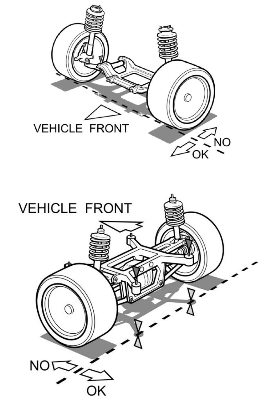
Front subframe must remain in the factory location: no relocation of the subframe on any plane will be
allowed
All original suspension mounting tabs must remain in the original position. NO cutting, welding, bending,
drilling or modifications of any kind will be allowed.
Front subframes may only be modified to directly allow for oil pan/ starter clearance and steering rack
relocation. The front subframe must remain intact on at least one major member on one face that spans the
entire width of the subframe, thereby keeping the original dimensions of the subframe intact. Any other
modifications, cutting, welding, strengthening, etc is not allowed.
3.2 STEERING
Modifications of steering components (steering rack, tie rods, etc) are free.
This includes mounting the rack to the front subframe.

17
3.3 REAR SUSPENSION- LIVE AXLE
The original chassis mounting points must remain unaltered and in the original factory position.
Suspension relocation brackets that move suspension points or pivots regardless if they are bolt in to the
chassis will not be allowed.
Original suspension design must remain: 3 link, 4 link, etc.
3.4 REAR SUSPENSION- INDEPENDENT
OEM Rear subframe and crossmember must be stock and available on the exact year make and model that is
competing in FORMULA DRIFT.
Original suspension design type must remain: 5 link, 4 link, strut, etc.
1. Suspension modifications must maintain the same link count as the factory hub.
2. Suspension link is defined as a rigid member with attachment/pivot point on the subframe/chassis and the
hub.
3. Example: if the factory hub has 5 attachment/pivot points on the hub and the subframe/chassis with 5
independent links then the aftermarket hub and arm configuration will also have 5 attachment/pivot
points on the hub and the subframe/chassis with 5 independent links to maintain the factory suspension
type.
The original chassis mounting points must remain unaltered and in the original factory position.
Modified or aftermarket suspension parts, including hubs, are allowed.
Subframe must remain at the factory height listed in the table below: no relocation of the subframe on any
plane will be allowed.
Make Year Model Front mounts Rear mounts
1990-2000 E36 0.640 0.465
1998-2006 E46 0.400 0.570
2004-2012 E90/92 0.520 0.630
Cadillac 2015-2018 ATS coupe 0.600 0.485
Chevrolet 2010- Camaro 0.741 1.547
Ford 2015 Mustang 0.400 0.400
Holden 2013-2017 UTE 0.925 1.585
Hyundai 2008- Genesis 0.765 0.635
Infiniti 2009-2013 G37 0.620 0.500
1989-1994 S13 0.675 0.600
1995-1998 S14 0.675 0.600
1999-2002 S15 0.675 0.600
2003-2009 350z 0.600 0.300
2010- 370z 0.725 0.200
2013- GTR 0.400 0.470
Mazda 2003-2012 RX-8 0.420 0.470
2001-2010 SC430 0.750 0.660
1991-2000 SC300 0.700 1.750
Scion 2010-2016 FRS 0.445 0.335
Subaru 2010- BRZ 0.445 0.335
Toyota 2016- GT86 0.445 0.335
Toyota 2019- Supra 0.425 0.310
BMW
Rear subframe to Chassis clearance (inch)
Tolerance ± .060 inch
Lexus
Nissan

18
If your vehicle is not listed and has a removable subframe please contact the Formula Drift Technical
Department.
If your vehicle has chassis tearing or subframe stud problems please contact the Formula Drift Technical
Department.
All original suspension and subframe mounting tabs must remain in the original position. NO cutting, welding,
bending, drilling or modifications of any kind will be allowed including subframe bushing to chassis mounts.
Additional mounting tabs may be added to the subframe to relocate the suspension arm mounting points
within a maximum of 2 inches on any plane from the original mounting position.
This will be measured center to center from the original pivot point to the new pivot point. Please refer to
Figure 8. This rule only applies to vehicles with a rear subframe and to pivot points on the rear subframe.
Rear subframes may be modified to allow for mounting or relocating a differential. The rear subframe must
retain at least one major member that spans the entire width of the subframe, thereby keeping the original
dimensions of the subframe intact. Any other modification(s) such as cutting, welding, strengthening, etc is not
allowed.
Figure 8

19
3.5 BRAKE SYSTEM
The primary brake system must hydraulically operate all 4 wheels.
Brake systems that use a single (non-tandem) master cylinder to operate all 4 wheels are prohibited.
Brake systems may be biased only front to rear. No brake bias may be used in a side to side configuration.
Dual master cylinder pedal assemblies are allowed.
Driver adjustable brake bias is allowed.
When a brake light pressure sensor is used it must be mounted in line with the front brake master cylinder and
have no restrictions in between.
Brake pressure switch must be mounted within 1 foot of the master cylinder.
Brake lights must operate with the ignition off, only the master cutoff being on is required for operation.
Secondary hydraulic e-brake systems are allowed as a fully separate system or as a pass through system.
Secondary Brake system / E-brake must only operate the rear wheels.
Carbon fiber, carbon ceramic, and carbon variant brakes or rotors are not allowed.
3.6 WHEELS
Beadlocks, wheel screws and any means of attachment between wheel and tire is prohibited.
The space between the rim and the internal portion of the tire must be filled only with air. Use of inner tubes,
tire balls, Mousse, Tubliss systems, and tire pressure relief valves are not allowed.
Wheels must be DOT approved for use on passenger car vehicles including bead seat profile and dimensions.
Center lock, mono lug, and center lug wheels are prohibited.
Carbon fiber or hybrid carbon fiber/alloy wheels are not allowed.
PRO Series vehicles will be required to have stickers on each tire or a contrasting color on a specific portion of
each wheel during official practices, qualifying and competition.
1. Tire stickers must be a minimum of 1 inch tall with 2 stickers per wheel.
2. Wheel coloration examples are in the figures below, the shaded areas are examples of allowed coloration
placement. If you have any questions regarding the visibility or allowed wheel coloration placement please
contact the Formula Drift Technical Department.

20
3.7 WHEELS TETHERS
Wheel tethers are recommended on the front and rear wheels.
DRIVETRAIN
4.1 ENGINE
Engine substitutions and modifications are free, but may only run on gasoline, diesel, and ethanol blends.
Electric and Hybrid power systems are eligible for competition with prior written approval from the
COMPETITION DIRECTOR.
Throttle Drive-By-Wire systems are eligible for competition, but teams must provide ECU and PDM data logs of
all system channels for all official practice and competition sessions at the conclusion of the event. Failure to
provide specified data will result in loss of up to and/or all competition points.
4.2 COOLING SYSTEM
Cooling system modifications are free but must be fully closed and free of leaks.
Automatic water sprayers will be allowed during competition, but must not be leaking on the track, starting
line, or grid area.
If cooling system lines are routed in the driver’s compartment or a trunk area that is open to the driver, they
must be separated from the driver by a crushable metal enclosure made up of .036-inch steel, or .059 inch
aluminum. The floor of the enclosure must be designed to prevent accumulation of fluids.
Cooling lines and fittings shielded with fire sleeve can be used in place of the metal shielding requirements.
Radiators located inside the driver’s compartment must be separated from the driver and may be ducted
through a maximum of two 10 inch holes in the chassis floor.
Cooling systems shall be filled with water only. Coolant Additives such as NEO “Keep Cool” and Redline “Water
Wetter” are allowed.
Radiator catch tanks with a minimum capacity of one (1) quart are required. Catch tanks must be securely
fastened and sealed from the driver’s compartment.
All engine components and exterior components that support engine operation such as coolers, pumps, tanks,
and lines must be protected and within the confines of the factory frame rails and factory bumper or tubular
bumper structure.
Skid plates are allowed for the protection of engine associated components such as lines for oil, cooling, and
fuel. Skid plates shall cover the minimal area needed for the protection of those components. Metallic skid
plates shall be made up of a maximum thickness of .125-inch steel or .1875-inch aluminum.
4.3 OIL SYSTEM
Oil system modifications are free but must be fully closed and free of leaks.
If the oil tank is located in the driver’s compartment area, or a trunk area that is open to the driver, it must be
separated from the driver by a metal enclosure made up of .036-inch steel, or .059-inch aluminum.
The floor of the enclosure must be designed to prevent accumulation of fluids.
Oil catch tanks with a minimum capacity of one (1) quart are required. Catch tanks must be securely fastened
and sealed from the driver’s compartment. Wristbands are recommended on all breather filters.
All engine components and exterior components that support engine operation such as oil cooler, Accu-sump,
dry-sump tank, oil filter, and oil lines must be protected and within the confines of the factory frame rails and
factory bumper or tubular bumper structure.
Skid plates are allowed for the protection of engine associated components such as lines for oil, cooling, and
fuel. Skid plates shall cover the minimal area needed for the protection of those components. Metallic skid
plates shall be made up of a maximum thickness of .125-inch steel or .1875-inch aluminum.

21
4.4 FUEL SYSTEM
4.4.1 FUEL TANK/ CELL
The fuel system design is free, but engines may only run on gasoline and ethanol blends. All other fuels require
written approval from the COMPETITION DIRECTOR.
Safety Fuel cells are required for all vehicles with a relocated fuel tank.
Safety fuel cells shall consist of a bladder enclosed in a metal container.
Safety fuel cell support structures must be welded to the vehicle. Bolt on support structures are prohibited.
If the factory fuel tank is retained, the tank must mounted in the factory location, and in the factory manner
while being enclosed by the factory sheet metal.
Drag race style fuel cells with bottom mount sumps and or fittings are prohibited. Fuel cells meeting SFI 28.1
are recommended.
Fuel tank/cell must be separated and completely sealed to prevent the passage of fluids or flames from
entering the driver’s compartment by a permanently mounted steel or aluminum bulkhead. The bulkhead in a
hatchback vehicle must be affixed to the chassis and no movable structure or panel such as the hatch will be
allowed as part of the bulkhead. Fuel cells may be installed in the interior of the vehicle, preferably within the
confines of the roll cage structure.
The floor pan may be modified to fit a fuel cell and lines.
Fuel cells must have a flapper valve installed to prevent spillage in the event of a roll over.
Fuel System must not leak on the track, starting line, or grid area.
Installation of Discriminator valves may be required on vent lines to prevent fuel leaks.
Pressurized refueling is prohibited.
Skid plates are allowed for the protection of engine associated components such as lines for oil, cooling, and
fuel. Skid plates shall cover the minimal area needed for the protection of those components. Metallic skid
plates shall be made up of a maximum thickness of .125-inch steel or .1875-inch aluminum.
4.4.2 FUEL LINES
Fuel lines and fittings must be high-pressure type and routed in such a way that do not interfere with moving
parts and be securely insulated and attached to the unibody or chassis.
No fuel lines may be routed through the driver’s compartment.
Teams may install dry-break fuel-filler attachments in the rear quarter windows or into the rear windshield or
trunk lid to facilitate re-fueling from outside the vehicle.
The fuel filler tube between the fuel filler neck and the fuel cell, or tank, must be bulk-headed with .036-inch
steel or .059-inch aluminum and sealed.
There shall be a flexible tube between the fuel filler neck and the fuel cell/tank to allow for misalignment of
the tube as the result of an accident as well as a one-way “flapper” valve.

22
4.5 NITROUS OXIDE
Nitrous Oxide bottles must be securely mounted inside the body line and protected within the confines of the
factory frame rails and factory bumper or tubular bumper structure.
All Nitrous bottles must be recertified every 5 years and stamped to indicate the last inspection date.
All Nitrous bottle must be stamped with minimum DOT -1800 pound rating.
The use of commercially available thermostatically controlled bottle warmers is accepted. The use of any other
method of externally heating nitrous bottles is prohibited.
The use of plastic bottle brackets is prohibited.
Nitrous bottles located in the driver compartment must have a “BLOW DOWN TUBE” which consists of a
pressure relief valve (Example from NOS- Part number NOS 16169) and be vented to the outside of the driver
compartment (Example from NOS- Part number NOS 16160).
4.6 EXHAUST SYSTEM
Exhaust system modifications are free, but must exit past the rear axle or in the original location.
Mufflers are not required.
4.7 STARTER
All vehicles must be equipped with an on-board starter and power supply which must be in working order at all
times
4.8 TRANSMISSION
All vehicles must be equipped with a functioning reverse gear.
Vehicles not equipped from the factory with a transaxle are prohibited from converting to a transaxle.
Factory equipped transaxle vehicles are allowed to convert to a separate transmission and differential.
Transmission and/or final drive modifications are free, but only the rear wheels may propel the vehicle.
As of 2020 all vehicles must be equipped with a SFI approved bellhousing meeting Spec 6.1, 6.2, or 6.3 and be
labeled accordingly.
If a SFI approved bellhousing meeting Spec 6.1, 6.2, or 6.3 is not commercially available, a flywheel shield may
be used.
• Flywheel Shield must:
o Be made of ¼ minimum thickness steel plate
o Be securely mounted to the chassis / unibody structure
o Completely surround the bellhousing in 360 degrees.
o Not be bolted to the bellhousing or the transmission
o Extend forward at least 1 inch ahead of the flywheel
o Extend 1 inch to the rear of the rotating components of the clutch and pressure plate.
As of 2020, Shifter and/or shift linkage must be covered with a SFI 48.1 approved shift boot.
Clutch release must be manually operated by driver’s foot.
Automatic transmission prohibited.
Automated, timer-type, pneumatic, electric, electronic, hydraulic, etc. shifting mechanism prohibited; each
individual shift must be a function of the driver and controlled manually.
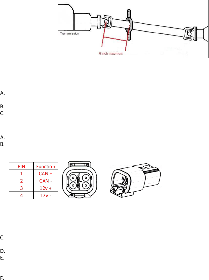
4.9 DRIVESHAFT
All vehicles must have a driveshaft retaining loop mounted within 6 inches of the forward most universal joint
and be securely attached to a unibody or frame structure as in Figure 9.
The driveshaft loop may be made of minimum .250-inch x 2-inch wide steel strap or .875-inch x .065-inch steel
tubing and be securely mounted in case of universal joint failure. (Example from Summit Racing- Part number
SUM-G7900)
23
Figure 9
4.10 DRIVER AIDS
Traction control, torque management, and other non-specified “driver aids” are not allowed including but not
limited to speed sensors, linear transducers, driveshaft rpm, and steering position.
The use of driver viewable in and on car cameras is strictly prohibited.
Wheel speed and driveshaft sensors must be removed.
4.11 DATA MONITORING
As of 2020 all vehicles are required to record data for the series.
All vehicles are required to provide a 4 pin DTM connector (DTM04-4P) wired according to the table below and
accessible from where the A-pillar meets the upper door bar on the passenger side of the vehicle.
Contacts are crimp type with male pins, the datasheet is available from Digikey.com search DTM04-4P.
Power must be supplied whenever the master cutoff switch is turned on.
Vehicles with the inability to transmit data will be subject to penalties such as loss of track time, fines, and/or
loss of series points.
These systems may be used for judging and technical purposes.
Any data collected is the property of FORMULA DRIFT, and discretion will be used to keep it confidential
between the team and FORMULA DRIFT as necessary, however data used for judging purposes may be
disclosed to other teams as appropriate.
If required, detail regarding sourcing, installation, and operation of a Data Acquisition system will be
referenced in official FORMULA DRIFT publications including but not limited to Supplemental Regulations,
Bulletins or Memos.

24
ELECTRICAL SYSTEM
5.1 BATTERY
The battery must be securely mounted and the positive terminal completely insulated to avoid contact with
any other metal parts.
A maximum of two batteries are allowed on vehicles with an internal combustion engine. All batteries must be
connected and in use.
Batteries may be relocated.
Relocated batteries must be fastened to the frame or unibody with a minimum of two 3/8-in diameter bolts.
Plastic hold down brackets and J bolts or hooks are prohibited.
If the battery is located in the driver’s compartment, it must be in a sealed box with the battery fastened inside
the box and securely bolted to the unibody/ chassis while being properly vented and drained.
Refer to Figure 10 (Example from Taylor Cable- Part number 48103)
Figure 10

25
5.2 MASTER CUTOFF
A master electrical cutoff switch is mandatory and must be wired to completely shut off all engine and
electrical system functions except for an electrically operated fire suppression system.
The master electrical cutoff switch must be mounted outside the vehicle on the driver’s side cowl just below
the windshield.
The master electrical cutoff switch must be easily accessible with the hood open or closed and be clearly
marked with the decal below.
The electrical terminals of the cut-off switch and/or any relays used in the circuit must be sufficiently insulated.
BODY EXTERIOR AND INTERIOR
6.1 BODY PANELS
Vehicles must maintain the OEM look and feel.
Panels must be clean, free of damage and presentable for competition.
All bodywork must be painted or covered and securely attached to the vehicle.
Aftermarket body panels, front and/or rear fascias, side skirts and wings are permitted.
One piece front ends are not permitted.
Over fenders are permitted and should be installed as in Figure 11.
Body work that is not designed as OEM or an OEM replacement of the original make and model of the vehicle
must be approved by the COMPETITION DIRECTOR.
Dimension A= 1 inch
Figure 11

26
Bumper bars must remain in the confines of the body lines and body work, without additional covers or body
work extensions in order to do so.
The bumper covers must be approved by Formula Drift and be acceptable to the COMPETITION DIRECTOR.
All aftermarket panels and aerodynamic devices must be securely fastened to the vehicle and are subject to
approval of the COMPETITION DIRECTOR.
6.2 DOORS
Doors must be mounted to the chassis with unmodified factory hinges. (quick release doors are prohibited)
Doors must use the factory latch mechanism
The inside and outside door latch/ lock operating mechanism must be functional and readily accessible for the
driver to exit the vehicle.
Doors with an exposed interior must have the sharp edges removed or covered.
6.3 WING
Wings that are multi-piece mounted on standoffs and those that are not directly attached to the trunk will be
prohibited at tracks where they may come into contact with walls, fencing, and signage. Examples of such
tracks include, but are not limited to Long Beach, Orlando, Wall, and Seattle.
No vertical aerodynamic elements may be added to vehicles other than two wing standoffs and two wing end
plates.
The size of each standoff and endplate may not exceed 12x16 inches dimensionally in size per piece. Refer to
Figure 12.
Wings with standoffs must have the endplates and the wing tethered with independent cables to the vehicle.
Contact Formula Drift for the specifications required on wing tethers.
Wings must be securely bolted to the vehicle use of quick release pins is prohibited.
The installation of these devices may not obstruct the view, from any angle, or operation any of safety device,
signaling light, indicator, or other equipment.
Figure 12

27

28
6.4 WINDSHIELD
Windshields must be OEM glass or Lexan/polycarbonate replacement.
Lexan/polycarbonate windshields must be a minimum thickness of .1875-inch
Lexan/polycarbonate windshields must be securely mounted and have a vertical brace .750-inch wide x .0625-
inch aluminum which is securely mounted down the center of the opening on inside the vehicle.
Windshields must be clear, use of tint is prohibited.
Vehicles with Lexan/ polycarbonate windshields must provide a permanent rigid camera mount at the top of
the windshield under the windshield banner for a stable mounting position of the dash camera.
6.5 WINDOWS and WINDOW RESTRAINTS
Door, quarter and rear window must be OEM glass or clear/polycarbonate with minimum thickness of .125-
inch and securely bolted in place.
Side windows shall have a window net, OEM glass, or a piece of Lexan/polycarbonate in place of both front
window openings whenever the vehicle is on-track.
Side windows and rear windows must be clear, use of tint or wrap is prohibited.
Competitors may choose to use arm restraints in lieu of side windows or a window net.
Competitors with convertible vehicles must use arm restraints.
6.6 WIPERS
Vehicles must have a functioning windshield wiper.
6.7 MIRRORS
A. Two external, rear-facing mirrors are required, and must be positioned so that the driver can see objects
along both sides of the vehicle.
B. OEM mirrors in the OEM mounting position are encouraged.
6.8 HOOD PINS
Two hood pins, equally spaced across the front of hood and are required within 24-inches of the leading edge
of the hood.
The original stock latch must be removed.
6.9 DECALS
All required FORMULA DRIFT and/or other decals or markings must be present in the specified location.
FORMULA DRIFT windshield banners are required.
FORMULA DRIFT reserves the right to have any decals, marks, or other items removed or covered at their
discretion.
No non-approved Formula DRIFT Tire Sponsor or Tire Supplier logos are permitted anywhere within the event
venue(s), on vehicle transports or rigs, competition vehicles, uniforms or driver suits. Additionally, no material
or promotional items are permitted with non-approved tire manufacturers branding and/or logos allowed at
Formula DRIFT events.

29
6.9.1 DECAL PLACEMENT
All competing vehicles must carry the following mandatory decals, as well as any other decals as mandated by
FORMULA DRIFT via supplemental regulations, memos, and other communications.
6.9.2 DECAL PLACEMENT KEY
1. (2) Formula Drift Number/ Name Plate. 1-inch x 1-inch from top of door
2. (1) Formula Drift Decal
3. (1) Formula Drift Windshield Banner
4. or 5. (1) Passenger side Formula Drift Sponsor Decal
Competitors may also be required to carry event specific sponsor/ contingency decals.
All vehicles must have the number plate in the designated area above.
Any alteration such as cutting or modifying is not allowed.
A minimum fine of $500 per event will be issued to any violators.

30
6.10 TOWING APPARATUS
Must be equipped front and rear as follows:
Load Rating of not less than the gross vehicle weight
Minimum internal hole diameter of 2inches
If made of a metal it must not protrude more than 3in from a blunt surface.
Colored in a contrasting color to the surrounding body work
If the towing apparatus is not clearly visible, the position must be clearly identified by the word “TOW” or an
arrow in a contrasting body color
6.11 LIGHTS
6.11.1 OEM LIGHTS
All OEM lights must remain in place, Headlights, tail lights and brake lights must function normally.
Brake lights and tail lights may only be red, tinting is prohibited.
Rearward facing strobe lights of any color is strictly prohibited.
Any variation of red and or orange colored headlights is prohibited.
Headlight replacements and modifications are subject to approval by the COMPETITION DIRECTOR.
The use of electrical, mechanical, and or hydraulic cutoff switches, relays, or any other device that renders the
brake lights inoperative in any way, is strictly prohibited.
6.11.2 THIRD BRAKE LIGHT STRIP
Front brake light strips must be removed from the vehicle.
Rear Brake light strip must be mounted on a fixed non removable panel or structure.
Contact Formula Drift for the updated brake light strip supplier list.
Brake light strips are 36 inches long and must remain 36 in long.
Damaged light strips with over 50% not functioning will need to be replaced prior to competition.
6.12 INTERIOR
The interior of the vehicle must be clean and professional in appearance.
Passenger side floor board must be clean and free of obstructions for a passenger such as a nitrous bottle, suit
coolers, and batteries.
All non-essential and/or loose items must be removed.
All carpeting and/or sound deadening material must be removed.
Supplemental Restraint Systems (SRS) must be removed.
6.13 DASHBOARD
The dashboard must be either stock or fiberglass stock appearing replacement.
Dash replacements must be same dimension, appearance, and position of stock dashboard.
Sheetmetal dashboards are prohibited.
6.14 STEERING WHEEL
Any steering wheel except wood rimmed may be used.
DRIVER’S SAFETY EQUIPMENT
7.1 HELMET
All occupants must wear a safety helmet during on-track sessions. Only helmets certified to meet the following
standards are permitted:
1. Snell Memorial Foundation – SA2010,SAH2010, SA2015
2. SFI Foundation – Spec 31.2A
3. FIA 8860-2004, 8860-2001
Full-faced helmets are required.
Helmet visors must be closed during on-track sessions.
Helmet chin straps must be buckled or fastened while on course.

31
Hair protruding from beneath a driver’s helmet must be completely covered by fire-resistant material. Drivers
with facial hair must wear face shields of fire-resistant material (i.e. balaclava or helmet skirt).
Accident-damaged helmets shall be given, or sent, by the driver, or his representative, to FORMULA DRIFT. It
will be forwarded to the certifying organization for inspection. Details of the accident should be included.
Cameras may not be mounted to competitor’s helmets.
7.2 DRIVING SUIT
One-piece driving suits are required and must be made of fire-resistant material and certified to SFI spec
3.2/A/5 or greater, or homologated to FIA 2000 specs, which effectively covers the body, including neck, ankles
and wrists. Multi-layer driving suits are recommended.
Gloves, shoes, and socks are required and must be fire-resistant material and certified to SFI spec 3.3/5 or
greater, or FIA 8856-2000 specs.
Articles must be free of holes, tears or other openings except those made by the manufacturer of the
equipment.
Fire-resistant underwear is recommended.
All drivers and teams must carry a FORMULA DRIFT series Logo on the uppermost chest of the driver’s suit and
team uniform. Other official series sponsor patches may be required.
Contact the FORMULA DRIFT office to obtain the digital file or patch.
7.3 EYE GLASSES
Any corrective eyeglass material used shall be of safety glass-type, and meet U. S. Government standards.
7.4 SEATS
All vehicles must have at least two seats, one for the driver, and one for a passenger.
Passenger side floor board must be clean and free of obstructions for a passenger such as a nitrous bottle, suit
coolers, and batteries.
Each of the two required seats must be homologated to FIA standard 8855-1999.
As of 2015 the driver’s seat must be “Halo style” for side impact head protection.
The usable life of an FIA homologated seat is 5 years from the date of manufacture indicated on the seat label.

32
Sample FIA seat homologation label:
The homologation labels must be visible
7.4.1 SEAT SUPPORT
Seat supports shall be of the type listed on FIA technical list No.12 (lateral, bottom, etc).
7.4.2 SEAT MOUNTING
A. All seats are to be mounted according to the seat manufacturer’s instructions.
B. The factory floor pan must remain intact with the exception of Nissan S chassis vehicles that are permitted to
remove the cat hump for the installation of seat brackets.
C. All hardware used in the mounting of seats, or other structural supports shall be SAE Grade 5 or better with a
5/16" minimum diameter.
7.5 SEAT BELTS
All occupants shall utilize a driver restraint system that conforms to these regulations.
All occupants in FORMULA DRIFT EVENTS must utilize either a five-point, or six-point, restraint harness
meeting the following specifications at all times during practice, qualifying, and the race.
A minimum five-point system is required for use in automobiles is required. The system consists of a two or
three in lap belt, three-inch shoulder straps or two-inch shoulder straps when used with an approved SFI 38.1
Head and Neck Restraint, and a single or double sub strap with a minimum two-inch webbing.
All Harness belts must meet either SFI or FIA Homologations:
There shall be a single release common to the lap belt, shoulder belts, and sub-strap harness.
SFI Certification – Harness systems may be certified to SFI spec 16.1 or 16.5 and shall bear the appropriate
label(s) on shoulder belts, lap belts and sub-straps.
SFI Certification- Each harness is printed with the specific year and date of expiration.
SFI 16.1 belts must have a 3 inch lap belt. 2 inch Head and Neck Restraint specific shoulders are permitted
when used with an approved SFI 38.1 Head and Neck Restraint.
SFI 16.5 belts may have a 2 or 3 inch lap belt. 2 inch Head and Neck Restraint specific shoulders are permitted
when used with an approved SFI 38.1 Head and Neck Restraint.
FIA Certification –Harness systems may be homologated by the FIA to specification 8853/98, and shall bear the
appropriate label(s) on each element of the belt. FIA belts are dated with an expiration year with the belts
expiring on December 31st of the year punched or printed on the FIA tags.
FIA belts have a certification period of 5 years plus the remaining months of the year purchased.
Regardless of the date of manufacture, the safety harness shall be replaced if the webbing is cut/ frayed, if any
of the buckles are bent/cracked, if the vehicle has been in a severe impact, or at the direction of the
COMPETITION DIRECTOR. If any of these conditions exist, the COMPETITION DIRECTOR shall cut the
certification labels off of the harness. The team will then have to replace the belt.
Only separate shoulder straps are permitted. “Y-type” and “H-Type” configurations are not allowed. Sternum
straps connecting the two shoulders belts over the chest are not allowed. The shoulder harness shall be
mounted as closely behind the seat back as possible, not to exceed twelve inches (12”). The shoulder harness
shall be above a line drawn downward from the shoulder point at an angle of no more than 20-degrees with
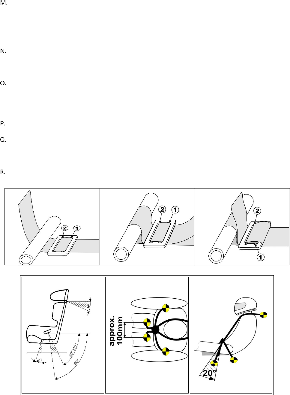
33
the horizontal and shall not be above 0-degrees. The shoulder straps shall pass through the seat back when the
occupant is seated, without interference (up, down, or side to side), to the attachment points. (Figure 1).
The lap belts shall be mounted rearward of the pelvis, between two lines drawn at 45-degrees, and 80-
degrees, below the horizontal with the optimum angle of 60-degrees (Figure 1). The lap belts shall pass
through the seat, without interference, from the attachment points and should ride over the pelvis, just below
the pelvic crest, to the buckle. The top of the buckle should be positioned at least 1-inch below the belly
button. The lap belt attachment must allow the lap belt to pivot at the mounting point to prevent the webbing
from being loaded at an edge when loaded and must pull on the hardware in plane.
The minimum acceptable bolts used in the mounting of all belts end harnesses are SAE Grade 5. Where
possible, seat belt, shoulder harness, and anti-submarine strap(s) should be mounted to the roll structure, or
frame of the vehicle. Where this is not possible, large diameter mounting washers or equivalent should be
used to spread the load. Bolting through aluminum floor panels, etc., is not acceptable.
The single or double anti-submarine strap(s) shall be attached to the floor structure of the vehicle and have a
metal-to-metal connection. Bolts through the floor pan must use a backing plate on the underside of the body.
If the chassis does not have a steel floor pan, other provisions must be made to provide a steel plate or bar
traversing the frame rails and transmission tunnel of sufficient strength to take a minimum load of at least
1,200lbs for each mounting point.
All seat belt systems are to be mounted according to the manufacturer’s instructions or to the SFI Guide to
Seat Belt Mounting (Figure 2)
If “3-bar” adjusters are used for a lap or shoulder belt, they shall be placed as close to the mounting points as
possible and must be wrapped with the final loop (Figure 4). Straps utilizing a hook with a spring-loaded clip,
which attaches to an eyebolt, must use a cotter pin, or safety wire, through the small hole that prevents the
clip from opening.
Occupants of convertible vehicles must use arm restraints.
The figure above is the preferred method for harness attachment to harness bar.
Figure 1
Figure 2
Figure 3

34
7.6 ARM RESTRAINTS
Competitors may choose to use arm restraints in lieu of windows or a window net.
Competitors with convertible vehicles must use arm restraints.
7.7 HEAD AND NECK RESTRAINTS
A Head and neck restraint certified in accordance with SFI 38.1, FIA 8858-2002 or 8858-2010 are required at all
times on track during practice and competition.
SFI 38.1 devices must be recertified by the manufacture or authorized manufacturer representative every 5
years. Each certification is good for 5 years from the month and year punched or printed on the SFI label.
FIA 8858 devices do not require recertification however the dating year printed on the tether must not be
more than 5 years old.
After any significant impact, it is recommended that the device tether be replaced.
7.8 FIRE SUPRESSION SYSTEM
All vehicles must have an on-board fire extinguishing system.
The bottle must be mounted so that it can be removed easily for verification of full charge by weighing.
A nozzle outlet must be directed into the driver compartment, but must not be pointed directly at the driver.
There shall also be a nozzle outlet in the fuel cell compartment and in the engine compartment.
If the fuel cell compartment is under the vehicle, or the stock fuel tank is being used, the third nozzle shall be
pointed at where the fuel lines come off the fuel tank/ cell or at the OE fuel tank access panel.
All fire systems shall be serviced and recertified every two years.
The proof of this service shall be printed on the exterior of the bottle. Only fire extinguisher systems
specifically approved by the FIA on Technical List No.16, or those meeting SFI spec 17.1 will be permitted.
7.8.1 APPROVED FIRE EXTINGUISHER SYSTEMS
Those approved by the FIA on Technical List No.16 or certified to SFI Spec 17.1
Note: while FIA technical list No.16 lists the systems approved by the FIA, section 3 of FIA Technical List No.6
lists the minimum amounts of extinguishant needed depending on the type of extinguisher system being used.
As a minimum, teams shall use the minimum amount of extinguishant listed for the driver’s compartment and
engine of Category N, A, B vehicles.
All systems must be equipped with a means of checking the pressure of the contents. This does not apply to
non-pressurized systems with a Co2 propellant cartridge.
7.8.2 INFORMATION THAT MUST BE VISIBLE ON THE CONTAINER:
Capacity
Type of extinguishant
Weight or volume of the extinguishant
Date the extinguisher must be checked, which must be no more than two years after the date of filling, or the
date of the last check.
7.8.3 FIRE SYSTEM MOUNTING
All extinguishers must be adequately protected and must be situated within the driver’s compartment.
In all cases, their mountings must be able to withstand a deceleration of 25 g.
All extinguishing equipment must withstand fire.

35
7.8.4 TRIGGERING DEVICES
Any triggering system having its own source of energy is permitted, provided it is possible to operate all
extinguishers should the main electrical circuits of the vehicle fail.
The driver, when seated normally with the safety belts fastened, and the steering wheel in place, must be able
to activate the fire system , by means of a spark proof breaker switch, or a manual push/pull apparatus.
This primary switch/apparatus must be located on the dashboard, center console, or driver’s side A-pillar and
must be marked with the decal pictured below.
If the fire system activation primary switch used by the driver is located on the driver’s side A-pillar then a
second fire system activation switch is not necessary.
Otherwise, a second fire system activation switch/apparatus must be fitted along the driver’s side A-pillar and
must be marked with the decal pictured below.
7.8.5 NOZZLES
The nozzles shall be of the same number and type as those specified by the manufacturer for use with the type
of extinguishant being used in the system.
Additionally, the nozzles shall be in the locations specified by the manufacturer.
7.8.6 SAFETY PINS
All fire safety pins must be removed while in staging, grid, and on course.
TIRES
8.1 APPROVED TIRES
No non-approved Formula DRIFT Tire Sponsor or Tire Supplier logos are permitted anywhere within the
event venue(s), on vehicle transports or rigs, competition vehicles, uniforms or driver suits. Additionally, no
material or promotional items are permitted with non-approved tire manufacturers branding and/or logos
allowed at Formula DRIFT events.
Only tires listed in the table below are eligible for competition.
Manufacturer
Model
Achilles
123S
Falken
Azenis RT-615K+
Azenis RT660
Azenis FK510
Ziex ZE950
Ziex ZE960
GT Radial
Champior SX2
Champior SX2 RS
Nexen
N FERA SUR4G
Nitto
NT05
NT555 G2

36
8.2 TIRE REGULATIONS
8.2.1 TIRE SIZE REGULATIONS
Vehicles are limited to the size of the rear tire that can be used, depending on the weight of the vehicle.
A vehicle must be track-ready and running when it is weighed and registered to a weight class.
A vehicle will be weighed with the driver
Once the vehicle is registered to a weight class, it will be recorded, and issued a class specific sticker that must
be displayed prominently on the windshield.
A vehicle's weight may fluctuate within the limits of its weight class, but it can never weigh less than the
minimum weight for its registered class.
Tire sizes are as measured in mm across the span of the contact patch with the official Formula Drift tire tool.
The Formula Drift tire tool will determine class compliance regardless of the advertised sidewall size.
Tires will be measured on the rim, while on the vehicle, while the vehicle is on the ground.
Tire size must not exceed the maximum size dictated by class at any time on track.
Tire size may be measured and verified on track before or after tandem rounds and qualifying.
A FORMULA DRIFT official may also check tire size at any time during the event.
8.2.2 TIRE TO WEIGHT COMPLIANCE
All vehicles must be weighed in a ready to drive state. All vehicles must weight within the designated weight
classes. No vehicles under 2100lbs or over 3399lbs. FORMULA DRIFT will include this weighing at a mandatory
pre-event inspection before the first event.
Vehicles will be weighed with driver, complete with all required bodywork and safety equipment installed.
Drivers must be fully suited with helmets during the weigh- in process. Vehicles may only be weighed and
registered upon passing their annual safety and technical inspection.
A vehicle can only be weighed and registered before the official start of a FORMULA DRIFT event. Vehicle may
be weighed before any event and only during the regular technical inspection hours provided.
The vehicle may not change weight classes at any time during an event. It is required of each competitor to
inform the COMPETITION DIRECTOR in writing of any modification(s) to their vehicle that alters the weight of
the vehicle by more than 10 lbs.
FORMULA DRIFT will be impounding all podium finishers immediately after end of competition and they will be
checked for weight and tire size compliance.
There will also be random compliance checks at any time during the FORMULA DRIFT events at FORMULA
DRIFT's discretion.
FORMULA DRIFT reserves the right to weigh vehicles at any time before, during or after an event.
Weight and Tire Classification
Weight
Maximum measured tire width
2100-2399lbs
240mm
2400-2699lbs
250mm
2700-2799lbs
260mm
2800-2899lbs
270mm
2900-2999lbs
280mm
3000-3099lbs
290mm
3100-3199lbs
300mm
3200-3299lbs
310mm
3300-3399lbs
320mm

37
8.3 TIRE MEASURING PROCEDURE
Rear tires will be measured while on the vehicle, on the ground, in a ready-to-drive state.
Tires will be measured across the width of the tread 3 inches up from where the tread meets the ground, from
the rear of the vehicle.
The measuring device is a flat sliding ruler with 2 legs extending out from the flat at 45 degrees. With the legs
contacting the sidewall, and the flat contacting the tread, the dimension defined by the scale is the measured
width of the tire.
For a tire to be compliant for a certain weight class it must fall within the designated size range within the
measuring device.
The official measuring tool will be available from FORMULA DRIFT directly for purchase.
8.3.1 TIRE MODIFICATION
Any attempt to modify tires in any manner is prohibited. “Grooving” or “Shaving” of tires is prohibited.
The use of traction compounds or any other substance that may alter the physical properties of the tire are
prohibited.
Tire warmers or any other means of artificially altering the tire temperatures are prohibited.
Tire balancing with fluids or internal loose weights is prohibited.
8.3.2 TIRE CLAIMING
A competitor has the right to “Claim” another competitor’s tires if they believe the tires are not within legal
specification. There are two types of claims:
NON COMPLIANT TREAD COMPOUND
Used in the event that a competitors tire compound is non-consistent with a specific make and model tire as it
is commercially available.
• A single tire will be identified by the Protestor, which will be removed and sent out for independent
analysis.
• Claiming Fee (Bond) to be paid to FORMULA DRIFT by protestor: $3,500. (may change due to lab fees)
TIRE COMPOUND TAMPERING
Used in the event that is a competitors tire has been tampered with, chemically treated, or altered in some way
so that it varies from a specific make and model tire as it is commercially available.
• Two tires must be claimed; the tire believed to have been altered, as well as an identical make and
model tire that has been used at the same specific, event, but which has not been altered.
• Claiming Fee (Bond) to be paid to FORMULA DRIFT by protestor: $3,500. (may change due to lab fees)
To make a claim, the Team Representative from the protestor must confidentially notify the COMPETITION
DIRECTOR of the claim via written notification accompanied by the claiming fee. Protest rules and time periods
apply.
The COMPETITION DIRECTOR will notify the team in question (protested) and mark the tires to be claimed.
The protested team will remove the marked tires and turn over custody to the COMPETITION DIRECTOR. The
COMPETITION DIRECTOR will ship the marked tires to Smithers Scientific Services for analysis.
If any of the tires are found to be non-compliant, the claiming fee will be returned to the protestor. The
COMPETITION DIRECTOR will report the technical infraction to the DISCIPLINARY COMMITTEE who will take
appropriate action including but not limited to fines, loss of points, or suspension of driver’s FORMULA DRIFT
License. The protested tire manufacturer, crew chief and/or vehicle owner may be subject to similar
disciplinary actions. Any non-compliant tires become property of FORMULA DRIFT.

38
If the tires are found to be compliant, the claiming free will be forfeited to FORMULA DRIFT.
8.4 TIRE MANUFACTURE ELIGIBILITY
Tire Manufacture eligibility consists of two components: sponsorship of the series and technical approval.
8.4.1 SPONSORSHIP OF THE SERIES
In addition to the monetary component tire suppliers must support a minimum of 3 Formula Drift PRO drivers
and provide onsite support to those teams using their tires. Please contact Formula Drift for promotional and
on-site branding details included with the sponsorship.
8.4.2 TECHNICAL APPROVAL
TIRE MODEL MUST:
1. Be submitted by the manufacture to Formula Drift
2. Be DOT approved and intended for Highway use
3. Be registered with the DOT and the NHTSA as having a minimum thread wear rating of 200 UTQG
4. Be available at regular retail outlets, online or storefront
5. All tires must have an MSRP of no more than $500.00
Tire manufacturers are required to declare each tire model that they wish to enter FORMULA DRIFT events, and
have that tire approved by FORMULA DRIFT prior to entering it for competition. A separate declaration package
is required for each tire model. This declaration must include:
TIRE MODEL
Full description of the tire line (i.e. Falken Azenis RT615K+, Falken Azenis FK510, or Falken PRO G4), model
numbers, part numbers, sizes, and rim diameters.
TIRE SPECIFICATION DATA SHEET
1. Physical Test Data:
a. Specific Gravity
b. Hardness (Shore A)
c. Tensile- (M-100%, M-300%, TS, EB)
d. Tg-
2. UTQG
a. Traction grade from skid test- (number results)
b. Treadwear grade- From actual road test (number results of wear)
c. Temperature grade- Actual resistance value from the testing
PROOF OF SUBMITTAL TO DOT, NHTSA, AND SAFERCAR.GOV
Be registered with the DOT and National Highway and Transportation Safety Administration as having a
minimum tread wear rating of 200 UTQG
PROOF OF RETAIL DISTRIBUTION
List at least two verifiable sources for retail distribution, including contact names, address and phone
numbers. These will be verified, and must be kept up to date.
MARKETING MATERIAL
Current examples of some type of commercial marketing, promotions, or sales material: PDFs, brochures,
flyers, advertisements, press releases, websites, etc.
Tire eligibility requests must be made at least 60 days prior to the expected competition date.

39
Record of Revisions
Release
Update
2.0
4.8 – Added section F.
If a SFI approved bellhousing meeting Spec 6.1, 6.2, or 6.3 is not commercially
available, a flywheel shield may be used.
• Flywheel Shield must:
o Be made of ¼ minimum thickness steel plate
o Be securely mounted to the chassis / unibody structure
o Completely surround the bellhousing in 360 degrees.
o Not be bolted to the bellhousing or the transmission
o Extend forward at least 1 inch ahead of the flywheel
o Extend 1 inch to the rear of the rotating components of the clutch and
pressure plate.
2.0
7.4.2 – In section D. added the word seat
D. All seats are to be mounted according to the seat manufacturer’s instructions.
3.0
2.1- Chassis Modifications- added list of variances
3.0
2.2.7- Cage Configurations updated illustrations and descriptions
3.0
3.4- Rear subframe to chassis clearance table update
3.0
6.3 C- Figure 12 updated
3.0
6.9.1- Decal chart updated
3.0
8.1- Approved tire chart update

40
