
Radiation Shielding and
Radiological Protection
J. Kenneth Shultis ⋅ Richard E. Faw
Department of Mechanical and Nuclear Engineering, Kansas
State University, Manhattan, KS, USA
jks@ksu.edu
fa[email protected].com
Radiation Fields and Sources ................................................
. Radiation Field Variables ...........................................................
.. Direction and Solid Angle Conventions .........................................
.. Radiation Fluence ...................................................................
.. Radiation Current or Net Flow ....................................................
.. Directional Properties of the Radiation Field ...................................
.. Angular Properties of the Flow and Flow Rate ..................................
. Characterization of Radiation Sources ...........................................
.. General Considerations ............................................................
.. Neutron Sources .....................................................................
.. Gamma-Ray Sources ................................................................
.. X-Ray Sources .......................................................................
ConversionofFluencetoDose...............................................
. Local Dosimetric Quantities .......................................................
.. Energy Imparted and Absorbed Dose ............................................
.. Kerma .................................................................................
.. Exposure ..............................................................................
.. Local Dose Equivalent Quantities.................................................
. Evaluation of Local Dose Conversion Coecients .............................
.. Photon Kerma, Absorbed Dose, and Exposure .................................
.. Neutron Kerma and Absorbed Dose .............................................
. Phantom-Related Dosimetric Quantities ........................................
.. Characterization of Ambient Radiation ..........................................
.. Dose Conversion Factors for Geometric Phantoms ............................
.. Dose Coecients for Anthropomorphic Phantoms............................
.. Comparison of Dose Conversion Coecients ..................................
Basic Methods in Radiation Attenuation Calculations.....................
. e Point-Kernel Concept .........................................................
.. Exponential Attenuation ...........................................................
.. Uncollided Dose from a Monoenergetic Point Source .........................
. Uncollided Doses for Distributed Sources .......................................
.. e Superposition Procedure......................................................
Dan Gabriel Cacuci (ed.), Handbook of Nuclear Engineering, DOI ./----_,
© Springer Science+Business Media LLC

Radiation Shielding and Radiological Protection
.. Example Calculations for Distributed Sources ..................................
Photon Attenuation Calculations............................................
. e Photon Buildup-Factor Concept .............................................
. Isotropic, Monoenergetic Sources in Innite Media ...........................
. Buildup Factors for Point and Plane Sources ....................................
.. Empirical Approximations for Buildup Factors .................................
.. Point-Kernel Applications of Buildup Factors...................................
. Buildup Factors for Heterogenous Media ........................................
.. Boundary Eects in Finite Media .................................................
.. Treatment of Stratied Media .....................................................
. Broad-Beam Attenuation of Photons .............................................
.. Attenuation Factors for Photon Beams...........................................
.. Attenuation of Oblique Beams of Photons.......................................
.. Attenuation Factors for X-Ray Beams ............................................
.. e Half-Value ickness ..........................................................
. Shield Heterogeneities ..............................................................
.. Limiting Case for Small Discontinuities .........................................
.. Small Randomly Distributed Discontinuities ...................................
Neutron Shielding ............................................................
. Neutron Versus Photon Calculations .............................................
. Fission Neutron Attenuation by Hydrogen ......................................
. Removal Cross Sections ............................................................
. Extensions of the Removal Cross Section Model ...............................
.. Eect of Hydrogen Following a Nonhydrogen Shield ..........................
.. Homogenous Shields................................................................
.. Energy-Dependent Removal Cross Sections ....................................
. Fast-Neutron Attenuation Without Hydrogen ..................................
. Intermediate and ermal Fluences ..............................................
.. Diusion eory for ermal Neutron Calculations ..........................
.. Fermi Age Treatment for ermal and Intermediate-Energy Neutrons .....
.. Removal-Diusion Techniques ...................................................
. Capture-Gamma-Photon Attenuation ...........................................
. Neutron Shielding with Concrete .................................................
.. Concrete Slab Shields ...............................................................
e Albedo Method ...........................................................
. Dierential Number Albedo .......................................................
. Integrals of Albedo Functions .....................................................
. Application of the Albedo Method ...............................................
. Albedo Approximations ............................................................
.. Photon Albedos......................................................................
.. Neutron Albedos ....................................................................
Skyshine.......................................................................
. Approximations for the LBRF .....................................................
.. Photon LBRF Approximation .....................................................
.. Neutron LBRF Approximation ....................................................

Radiation Shielding and Radiological Protection
. O p e n S i l o E x a m pl e ..................................................................
. Shielded Skyshine Sources .........................................................
. Computational Resources for Skyshine Analyses ...............................
Radiation Streaming rough Ducts ........................................
. Characterization of Incident Radiation ..........................................
. Line-of-Sight Component for Straight Ducts ...................................
.. Line-of-Sight Component for the Cylindrical Duct ............................
.. Line-of-Sight Component for the Rectangular Duct ...........................
. Wall-Penetration Component for Straight Ducts ...............................
. Single-Scatter Wall-Reection Component......................................
. Photons in Two-Legged Rectangular Ducts .....................................
. Neutron Streaming in Straight Ducts.............................................
. Neutron Streaming in Ducts with Bends ........................................
.. Two-Legged Ducts ..................................................................
.. Neutron Streaming in Ducts with Multiple Bends .............................
. Empirical and Experimental Results..............................................
Shield Design .................................................................
. Shielding Design and Optimization ..............................................
. Shielding Materials ..................................................................
.. Natural Materials ....................................................................
.. Concrete ..............................................................................
.. Metallic Shielding Materials .......................................................
.. Special Materials for Neutron Shielding .........................................
.. Materials for Diagnostic X-Ray Facilities ........................................
. A Review of Soware Resources ..................................................
. Shielding Standards .................................................................
Health Physics ................................................................
. Deterministic Eects from Large Acute Doses..................................
.. Eects on Individual Cells .........................................................
.. Deterministic Eects in Organs and Tissues ....................................
.. Potentially Lethal Exposure to Low-LET Radiation ............................
. Hereditary Illness....................................................................
.. Classication of Genetic Eects ...................................................
.. Estimates of Hereditary Illness Risks .............................................
. Cancer Risks from Radiation Exposures .........................................
.. Estimating Radiogenic Cancer Risks .............................................
. e Dose and Dose-Rate Eectiveness Factor ..................................
.. Dose–Response Models for Cancer...............................................
.. Average Cancer Risks for Exposed Populations .................................
. Radiation Protection Standards ...................................................
.. Risk-Related Dose Limits ..........................................................
.. e NCRP Exposure Limits..................................................
References .....................................................................

Radiation Shielding and Radiological Protection
Abstract: is chapter deals with shielding against nonionizing radiation, specically gamma
rays and neutrons with energies less than about MeV, and addresses the assessment of health
eects from exposure to such radiation. e chapter begins with a discussion of how to char-
acterize mathematically the energy and directional dependence of the radiation intensity and,
similarly, the nature and description of radiation sources. What follows is a discussion of how
neutrons and gamma rays interact with matter and how radiation doses of various types are
deduced from radiation intensity and target characteristics. is discussion leads to a detailed
description of radiation attenuation calculations and dose evaluations, rst making use of
the point-kernel methodology and then treating the special cases of “skyshine” and “albedo”
dose calculations. e chapter concludes with a discussion of shielding materials, radiological
assessments, and risk calculations.
Radiation Fields and Sources
e transmission of directly and indirectly ionizing radiation through matter and its inter-
action with matter is fundamental to radiation shielding design and analysis. Design and
analysis are but two sides of the same coin. In design, the source intensity and permissible
radiationdoseordoserateatsomelocationarespecied,andthetaskistodeterminethe
type and conguration of shielding that is needed. In analysis, the shielding material is spec-
ied, and the task is to determine the dose, given the source intensity, or the latter, given the
former.
e radiation is conceptualized as particles – photons, electrons, neutrons, and so on. e
term radiation eld refers collectively to the particles and their trajectories in some region of
space or through some boundary, either per unit time or accumulated over some period of time.
Characterization of the radiation eld, for any one type of radiation particle, requires a
determination of the spatial variation of the joint distribution of the particle’s energy and direc-
tion. In certain cases, such as those encountered in neutron scattering experiments, properties
such as spin may be required for full characterization. Such infrequent and specialized cases are
not considered in this chapter.
e sections to follow describe how to characterize the radiation eld in a region of space
in terms of the particle uence and how to characterize the radiation eld at a boundary in
terms of the particle ow. e uence and ow are called radiometric quantities, as distinguished
from dosimetric quantities. e uence and ow concepts apply both to measurement and cal-
culation. Measured quantities are inherently stochastic, in that they involve enumeration of
individual particle trajectories. Measurement, too, requires nite volumes or boundary areas.
e same is true for uence or ow calculated by Monte Carlo methods, because such calcula-
tions are, in large part, computer simulations of experimental determinations. In the methods of
analysis discussed in this chapter, the uence or ow is treated as a deterministic point function
and should be interpreted as the expected value, in a statistical sense, of a stochastic variable.
It is perfectly proper to refer to the uence, ow, or related dosimetric quantity at a point in
space. But it must be recognized that any measurement is only a single estimate of the expected
value.

Radiation Shielding and Radiological Protection
. Radiation Field Variables
.. Direction and Solid Angle Conventions
e directional properties of radiation elds are commonly described using spherical polar
coordinatesasillustratedin
> Fig. . e direction vector is a unit vector, given in terms of the
orthogonal Cartesian unit vectors i, j,andk by
Ω =iu +ν +kω =i sin θ cos ψ +j sin θ sin ψ +k cos θ.()
An increase in θ by dθ and ψ by dψ sweeps out the area dA =sin θdθdψon a sphere of unit
radius. e solid angle encompassed by a range of directions is dened as the area swept out
on the surface of a sphere divided by the square of the radius of the sphere. us, the dier-
ential solid angle associated with the dierential area dA is dΩ =sin θdθdψ.esolidangle
is a dimensionless quantity. Nevertheless, to avoid confusion when referring to a directional
distribution function, units of steradians, abbreviated sr, are attributed to the solid angle.
A substantial simplication in notation can be achieved by making use of ω ≡cos θ as an
independent variable instead of the angle θ,sothatsin θdθ=−dω. e benet is evidentwhen
one computes the solid angle subtended by “all possible directions,” namely,
Ω =
π
dθ sin θ
π
dψ =
−
dω
π
dψ =π.()
Y
Z
X
dA
y
w
dq
u
v
dy
q
W
⊡ Figure
Spherical polar coordinate system for specification of the unit direction vector Ω, polar angle θ,
azimuthal angle ψ, and associated direction cosines (u, ν, ω)

Radiation Shielding and Radiological Protection
.. Radiation Fluence
A fundamental way of characterizing the intensity of a radiation eld is in terms of the number
of particles that enter a specied volume. To make this characterization, the radiometric con-
cept of uence is introduced. e particle uence, or simply uence, at any point in a radiation
eld may be thought of in terms of the number of particles ΔN
p
that, during some period of
time, penetrate a hypothetical sphere of cross section ΔA centered on the point, as illustrated
in
> Fig. a. e uence is dened as
Φ ≡ lim
ΔA→
ΔN
p
ΔA
.()
An alternative, and oen more useful denition of the uence, is in terms of the sum
∑
i
s
i
of
path-length segments within the sphere, as illustrated in
> Fig. b.euencecanalsobe
dened as
Φ ≡ lim
ΔV →
∑
i
s
i
ΔV
.()
Although the dierence quotients of ()and() are useful conceptually, beginning in ,
the ICRU prescribed that the uence should be given in terms of dierential quotients, in
recognition that ΔN
p
is the expectation value of the number of particles entering the sphere.
us, Φ ≡dN
p
dA,wheredN
p
is the number of particles which penetrate into a sphere of
cross-sectional area dA.
e uence rate, or ux, is expressed in terms of the number of particles entering a sphere,
or the sum of path segments traversed within a sphere, per unit time, namely,
ϕ ≡
dΦ
dt
=
d
N
p
dAdt
.()
DV
DV
DA
ab
⊡ Figure
Element of volume ΔV in the form of a sphere with cross-sectional area ΔA.In(a) the attention is
on the number of particles passing through the surface into the sphere. In (b) the attention is on
the paths traveled within the sphere by particles passing through the sphere

Radiation Shielding and Radiological Protection
.. Radiation Current or Net Flow
Another radiometric measure of a radiation eld is the net number of particles crossing a sur-
face with a well-dened orientation, as illustrated in
> Fig. .enet particle ow (or simply
net ow) at a point on a surface is the net number of particles in some specied time interval
that ow across a unit dierential area on the surface, in the direction specied as positive. As
showninthegure,onesideofthesurfaceischaracterizedasthepositivesideandisidenti-
ed by a unit vector n normal to the area ΔA. If the number of particles crossing ΔA from the
negative to the positive side is ΔM
+
p
and the number from the positive to the negative side is
ΔM
−
p
, then the net number crossing toward the positive side is ΔM
p
≡ΔM
+
p
−ΔM
−
p
.enet
ow at the given point is designated as J
n
, with the subscript denoting the unit normal n from
the surface, and is dened as
J
n
≡ lim
ΔA→
ΔM
p
ΔA
=
dM
p
dA
.()
e total ow of particles in the positive and negative directions, J
+
n
and J
−
n
,aredenedinterms
of ΔM
+
p
and ΔM
−
p
in a similar manner. e relation between the net ow and the positive and
negative ows is J
n
≡J
+
n
−J
−
n
.
e net ow rate is expressed in terms of the net number of particles crossing an area
perpendicular to unit vector n, per unit area and per unit time, namely, j
n
≡j
+
n
−j
−
n
.
e concepts of uence and particle ow appear to be very similar, both being dened in
terms of a number of particles per unit area. However, for the concept of the uence, the area
presented to incoming particles is independent of the direction of the particles, whereas for the
particle ow concept, the orientation of the area is well dened.
n
+
+
-
-
Surface
ΔA
⊡ Figure
Element of area ΔA in a surface. Particles cross the area from either side

Radiation Shielding and Radiological Protection
.. Directional Properties of the Radiation Field
e computed uence is a point function of position r.Measurementoftheuencerequiresa
radiation detector of nite volume; therefore, there is not only uncertainty due to experimental
error but also ambiguity in identication of the “point” at which to attribute the measurement.
e nature of the particles is implicit, and the argument r in Φ(r)is sometimes implicit. With
no other arguments, Φ or Φ(r)represents the total uence irrespective of particle energy or
particle direction, that is, integrated over all particle energies and directions.
In many circumstances, it is necessary to broaden the concept of the uence to include infor-
mation about the energies and directions of particles. To do so requires the use of distribution
functions. Particle energies and directions require, in general, uences expressed as distribution
functions. For example, Φ(r, E)dE is, at point r,theuence energy spectrum –theuenceof
particles with energies between E and E +dE.
e angular dependence of the uence is a bit more complicated to write. e angular vari-
able itself is the vector direction Ω. e direction is a function of the polar and azimuthal angles,
θ and ψ. Similarly, the dierential element of solid angle is a function of the same two variables,
namely dΩ =sin θdθdψ=dωdψ.us,Φ(r, Ω)dΩ or Φ(r, ω, ψ)dωdψ is, at point r,the
angular uence – the uence of particles with directions in dΩ about Ω. e joint energy and
angular distribution of the uence is dened in such a way that Φ(r, E, Ω)dEdΩ is the uence
of particles with energies in dE about
Eandwith directions in dΩ about Ω.
In the system of notation adopted here, it is necessary that the energy and angular variables
appear specically as arguments of Φ to identify the uence as a distribution function in these
variables. e ICRU notation refers to the energy distribution as the spectral distribution and to
the angular distribution as the radiance.
.. Angular Properties of the Flow and Flow Rate
Just as it is very oen necessary to account for the variation of the uence with particle energy
and direction, the same is true for the ow and ow rate. Treatment of the energy dependence
is no dierent from the treatment used for the uence, so here only the angular dependence
of the ow is examined. With an element of area and its orientation as illustrated in
> Fig. ,
it is perfectly proper to dene the angular ow in such a way that J
n
(r, Ω)dΩ is the ow of
particles through a unit area with directions in dΩ about Ω. e corresponding angular ow
rate is written as j
n
(r, Ω).
> Figure illustrates particles within a dierential elementof direction dΩabout direction
Ω crossing a surface perpendicular to unit vector n. Also shown in the gure is a sphere whose
surface just intercepts all the particles. It is apparent that if ΔAis the cross-sectional area of the
sphere, then the corresponding area in the surface is ΔA sec θ,wherecosθ =n
●
Ω.us,because
the same number of particles pass through the sphere and through the area in J
n
(r, Ω)ΔA =
cos θΔAΦ(r, Ω),or
J
n
(r, Ω)=n
●
ΩΦ(r, Ω).()
e net ow is given by
J
n
(r)≡
π
dΩ J
n
(r, Ω) ()
=
π
dΩ n
●
ΩΦ(r, Ω).

Radiation Shielding and Radiological Protection
ΔA
ΔA sec q
q
W
n
⊡ Figure
J
n
(r, Ω) versus Φ(r, Ω)
e uence is a positive quantity; however, J
n
(r, Ω)is positive or negative as n
●
Ω is positive or
negative. at part of the integral for which n
●
Ω is positive is the ow J
+
n
(r),andthatpartfor
which n
●
Ω is negative is −J
−
n
(r). e algebraic sum of the two parts gives the net ow J
n
(r).
. Characterization of Radiation Sources
.. General Considerations
e most fundamental type of source is a point source. A real source can be approximated
as a point source provided that () the volume is suciently small, that is, with dimensions
much smaller than the dimensions of the attenuating medium between the source and detector,
and () there is negligible interaction of radiation with the matter in the source volume. e
second requirement may be relaxed if source characteristics are modied to account for source
self-absorption and other source–particle interactions.
In general, a point source may be characterized as depending on energy, direction, and time.
In almost all shielding practices, time is not treated as an independent variable because the time
delay between a change in the source and the resulting change in the radiation eld is usually
negligible. erefore, the most general characterization of a point source used here is in terms of
energy and direction, so that S
p
(E, Ω)dEdΩ is the number of particles emitted with energies
in dE about E and in dΩ about Ω. Common practical units for S
p
(E, Ω)are MeV
−
sr
−
or
MeV
−
sr
−
s
−
.
Most radiation sources treated in the shielding practice are isotropic, so that source char-
acterization requires only knowledge of S
p
(E)dE, which is the number of particles emitted
with energies in dE about E (per unit time), and has common practical units of MeV
−
(or MeV
−
s
−
). Radioisotope sources are certainly isotropic, as are ssion sources and capture
gamma-ray sources.

Radiation Shielding and Radiological Protection
A careful distinction must be made between the activity of a radioisotope and its source
strength. Activity is precisely dened as the expected number of atoms undergoing radioac-
tive transformation per unit time. It is not dened as the number of particles emitted per
unit time. Decay of two very common laboratory radioisotopes illustrate this point. Each
transformation of
Co, for example, results in the emission of two gamma rays, one at .
MeV and the other at . MeV. Each transformation of
Cs, accompanied by a trans-
formation of its decay product
m
Ba, results in emission of a .-MeV gamma ray with
probability ..
e SI unit of activity is the becquerel (Bq), equivalent to transformation per second. In
medical and health physics, radiation source strengths are commonly calculated on the basis of
accumulated activity, Bq s. Such time-integrated activities account for the cumulative number
of transformations in some biological entity during the transient presence of radionuclides in
the entity. Of interest in such circumstances is not the time-dependent dose rate to that entity or
some other nearby region, but rather the total dose accumulated during the transient. Similar
practices are followed in dose evaluation for reactor transients, solar ares, nuclear weapons,
and so on.
Radiation sources may be distributed along a line, over an area, or within a volume.
Source characterization requires, in general, spatial and energy dependence, with S
l
(r, E)dE,
S
a
(r, E)dE,andS
v
(r, E)dE representing, respectively, the number of particles emitted in dE
about E per unit length, per unit area, and per unit volume. Occasionally, it is necessary to
include angular dependence. is is especially true for eective area sources associated with
computed angular ows across certain planes. Clearly, for a xed surface, S
a
(r, E, Ω)and
J
n
(r, E, Ω)are equivalent specications.
Energy dependence may be discrete, such as for radionuclide sources, or continuous, as
for bremsstrahlung or ssion neutrons and photons. When discrete energies are numerous,
an energy multigroup approach is oen used. e same multigroup approach may be used to
approximately characterize a source whose emissions are continuous in energy.
.. Neutron Sources
Fission Sources
Many heavy nuclides ssion aer the absorption of a neutron, or even spontaneously, producing
several energetic ssion neutrons. Fission neutrons may produce secondary radiation sources,
such as inelastic-scattering photons and capture gamma photons, and may transmute stable
isotopes into radioactive ones.
Almost all of the fast neutrons produced from a ssion event are emitted within
−
softhe
ssion event. Less than % of the total ssion neutrons are emitted as delayed neutrons,which
are produced by the neutron decay of ssion products at times up to many minutes aer the
ssion event. Except for very specialized situations, these delayed neutrons, which are emitted
with signicantly less energy than the prompt neutrons, are of little importance in shield design
because of their relatively small yield and low energies.
As the energy of the neutron which induces the ssion in a heavy nucleus increases, the
average number of ssion neutrons also increases. Yields in thermal-neutron induced ssion of
U,
Pu, and
U are respectively ., ., and .. See Keepin () for information on
epithermal- and fast-neutron induced ssion.

Radiation Shielding and Radiological Protection
Many transuranic isotopes have appreciable, spontaneous ssion probabilities; and conse-
quently, they can be used as very compact sources of ssion neutrons. For example, g of
Cf
releases . ×
neutrons per second, and very intense neutron sources can be made from
this isotope, limited in size only by the need to remove the ssion heat through the necessary
encapsulation. Properties of the spontaneously ssioning isotopes of greatest importance in
spent nuclear fuel are listed in
> Table . Almost all of these isotopes decay much more rapidly
by α emission than by spontaneous ssion.
e energy dependence of the ssion neutron spectrum has been investigated extensively,
especially that for
U. All ssionable nuclides produce a distribution of prompt ssion-
neutron energies which goes to zero at low and high energies and reaches a maximum at about
. MeV. e fraction of prompt ssion neutrons emitted per unit energy about E, χ(E),canbe
described quite accurately by a modied two-parameter Maxwellian distribution (a Maxwellian
corrected for the average energy of the ssion fragments in the laboratory coordinate system),
namely,
χ(E)=
e
−(E+E
ω
)/T
ω
√
πE
ω
T
ω
sinh
E
ω
E
T
ω
.()
In many shielding applications, the spectrum for thermal-neutron-induced ssion of
U
has oen been used, at least as a rst approximation for other ssioning isotopes, although
U,
Pu, and
Cf have somewhat greater high-energy components; and consequently, their
ssion neutrons are slightly more penetrating than those of
U. Please refer to > Table for
parameter values.
Photoneutrons
A gamma photon with energy suciently larger to overcome the neutron-binding energy
(about MeV in most nuclides) may cause a (γ, n)reaction. Very intense and energetic pho-
toneutron production can be realized in an electron accelerator where the bombardment of an
appropriate target material with the energetic electrons produces intense bremsstrahlung with
a distribution of energies up to that of the incident electrons.
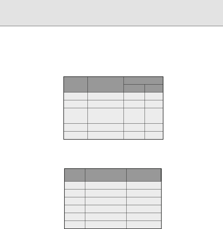
⊡ Table
Selected nuclides which spontaneously fission. All also decay by alpha emission,
which is usually the only other decay mode
Nuclide Half-life
Fission prob.
per decay (%)
Neutrons
per fission
α per
fission
Neutrons
per (g s)
Pu . y . ×
−
. . ×
. ×
Pu y . ×
−
. . ×
Pu . ×
y . ×
−
. . ×
. ×
Cm d . ×
−
. . ×
. ×
Cm . y . ×
−
. . ×
. ×
Cm y . . . ×
. ×
Cf . y . . . ×
Sources: Data compiled from Dillman (), Kocher (), and Reilly et al. (), and from the
NuDat data resource of the National Nuclear Data Center at Brookhaven National Laboratory
Radiation Shielding and Radiological Protection
⊡ Table
Parameters for the Watt approximationfor the prompt
fission-neutron distribution for various fissionable
nuclides. Values for
Cf are from Fröhner ().
The other values were obtained by a logarithmic
fit of the Watt formula to the calculated spectra by
Walsh ()
Equation ()
Nuclide Type of fission E
w
T
w
U Thermal . .
U Thermal . .
Pu Thermal . .
Th Fast ( MeV) . .
U Fast ( MeV) . .
Cf Spontaneous . .
⊡ Table
Important nuclides for photoneutron production
Nuclide
Threshold
E
t
(MeV)
(−
Q
value)
Reaction
H .
H(γ, n)
H
Li .
Li(γ, n + p)
He
Li .
Li(γ, n)
Li
Li .
Li(γ, n)
Li
Be .
Be(γ, n)
Be
C .
C(γ, n)
C
In reactor shielding analyses, the gamma photons encountered have energies too low, and
most materials have a photoneutron threshold too high for photoneutrons to be of concern.
Only for a few light elements, listed in
> Table , are the thresholds for photoneutron pro-
duction suciently low that these secondary neutrons may have to be considered. In heavy
water- or beryllium-moderated reactors, the photoneutron source may be very appreciable,
and the neutron-eld deep within a hydrogenous shield is oen determined by photoneutron
production in deuterium, which constitutes about . at% of the hydrogen. Capture gamma
photons arising from neutron absorption have particularly high energies and, thus, may cause
a signicant production of energetic photoneutrons.
e photoneutron mechanism can be used to create laboratory neutron sources by mixing
intimately a beryllium or deuterium compound with a radioisotope that decays with the emis-
sion of high-energy photons. Alternatively, the encapsulated radioisotope may be surrounded

Radiation Shielding and Radiological Protection
by a beryllium- or deuterium-bearing shell. One common laboratory photoneutron source is
an antimony–beryllium mixture, which has the advantage of being rejuvenated by exposing the
source to the neutrons in a reactor to transmute the stable
Sb into the required
Sb isotope
(half-life of . days). Other common sources are mixtures of
Ra and beryllium or heavy
water.
One very attractive feature of such (γ, n)sources is the nearly monoenergetic nature of
the neutrons if the photons are monoenergetic. However, in large sources, the neutrons may
undergo signicant scattering in the source material, and thereby degrade the nearly monoen-
ergetic nature of their spectrum. ese photoneutron sources generally require careful usage
because of their inherently large, photon emission rates. Because only a small fraction of the
high-energy photons (typically,
−
) actually interact with the source material to produce a
neutron, these sources generate gamma rays that are of far greater biological concern than the
neutrons.
Neutrons from (α, n) Reactions
Many compact neutron sources use energetic alpha particles from various radioisotopes (emit-
ters)toinduce(α, n)reactions in appropriate materials (converters). Although a large number
of nuclides emit neutrons if bombarded with alpha particles of sucient energy, the energies
of the alpha particles from radioisotopes are capable of penetrating the Coulombic potential
barriers of only the lighter nuclei.
Of particular interest are those light isotopes for which the (α, n)reaction is exothermic
(Q >) or, at least, has a low threshold energy (see
> Table ). For endothermic reactions, the
threshold alpha energy is −Q( +A).us,foran(α, n)reaction to occur, the alpha particle
must () have enough energy to penetrate the Coulomb barrier, and () exceed the threshold
energy. Alpha particles emitted by uranium and plutonium range between and MeV and can
cause (α, n)neutron production when in the presence of oxygen or uorine. Neutrons from
(α, n)reactions oen exceed the spontaneous ssion neutrons in UF
or in aqueous mixtures
of uranium and plutonium such as found in nuclear waste (Reilly et al. ).
A neutron source can be fabricated by mixing intimately one of the converter isotopes listed
in
> Table with an alpha-particle emitter. Most of the practical alpha emitters are actinide
elements, which form intermetallic compounds with beryllium. Such a compound (e.g., PuBe
)
⊡ Table
Important (α, n) reactions
Target
Natural
abundance
(%)
Reaction
energy (MeV)
(Q value)
Threshold
energy
(MeV)
Coulomb
barrier
(MeV)
Be
Be(α, n)
C . Exothermic .
Be
Be(α, n)α −. . .
B .
B(α, n)
N . Exothermic .
B .
B(α, n)
N . Exothermic .
O .
O(α, n)
Ne −. . .
F
F(α, n)
Na −. . .

Radiation Shielding and Radiological Protection
ensures both that the emitted alpha particles immediately encounter converter nuclei, thereby
producing a maximum neutron yield, and that the radioactive actinides are bound into the
source material, thereby reducing the risk of leakage of the alpha-emitting component. Some
characteristics of selected (α, n)sources are listed in
> Table .
e neutron yield from an (α, n)source varies strongly with the converter material, the
energy of the alpha particle, and the relative concentrations of the emitter and converter ele-
ments. e degree of mixing between the converter and emitter, and the size, geometry, and
source encapsulation may also aect the neutron yield.
e energy distributions of neutrons emitted from all such sources are continuous below
some maximum neutron energy with denite structure at well-dened energies determined by
the energy levels of the converter and the excited product nuclei. e use of the same converter
material with dierent alpha emitters produces similar neutron spectra with dierent portions
of the same basic spectrum accentuated or reduced as a result of the dierent alpha-particle
energies.
Generally, neutrons emitted from the
Be(α, n)reaction have higher energies than those
produced by other (α, n)sources because Be has a larger Q value than that of other converters.
e structure in the Be-produced neutron spectrum above MeV can be interpreted in terms
of structure in the
Be(α, n)
C cross section, which in turn depends on the excitation state
in which the
C nucleus is le. A large peak below MeV in the Be neutron spectrum arises
not from the direct (α, n)reaction, but from the “breakup” reaction
Be(α, α
′
)
Be
∗
→
B +n.
As the alpha-particle energy increases, both the fraction of neutrons emitted from the breakup
reaction (E
n
< MeV) and the probability that the product nucleus is le in an excited state
(E
n
< MeV) increase, thereby decreasing slightly the average neutron energy (see > Table ).
In all (α, n)sources, there is a maximum neutron energy corresponding to the reaction
in which the product nucleus is le in the ground state and the neutron appears in the same
direction as that of the incident alpha particle (θ =).us,unlikessionneutronsources,
there are no very high energy neutrons generated in an (α, n)source.
⊡ Table
Characteristics of some (α, n) sources
Principal Average Optimum neutron
Half- alpha energies neutron yield per
Source life (MeV) energy (MeV) primary alphas
a
Pu / Be y ., ., . .
Po / Be . d . .
Pu / Be . y ., ., . .
Am / Be y ., ., . .
Ra / Be y ., ., . .
b
+ daughters ., ., .
Sources: Jaeger (), GPO (), and Knoll ()
a
Yield for alpha particles incident on a target thicker than the alpha-particle ranges
b
Yield is dependent on the proportion of daughters present. Value for
Ra corresponds to a
-year-old source (% contribution for
Po)

Radiation Shielding and Radiological Protection
With appropriate (α, n)cross-section data for a converter, ideal neutron energy spectra
can be calculated for the monoenergetic alpha particles emitter by dierent alpha emitters
(Geiger and Van der Zwan ). However, these ideal spectra are modied somewhat in
actual (α, n)sources. e monoenergetic alpha particles lose variable amounts of energy
through ionization interactions in the source material before inducing an (α, n)reaction.
is eectively continuous nature of the alpha-particle energy spectrum tends to smooth out
many of the ne features of the ideal neutron spectrum. Further, if the source is physically
large as a result of requiring a large activity (e.g., a
Pu/Be source emitting
neutrons
per second requires about g of plutonium), neutron interactions within the source itself
may alter the emitted neutron spectrum. Neutron scattering, (n,n)reactions with beryl-
lium, and even neutron-induced ssion of the actinide converter change the neutron energy
spectrum slightly. Finally, impurity nuclides, which also emit alpha particles, as well as the
buildup of alpha-emitting daughters, aect the neutron energy spectrum. In general, the neu-
tron energy spectrum as well as the yield depend in a very complicated manner on the
composition, size, geometry, and encapsulation of the source. Fortunately, in most shielding
applications only approximate energy information is needed and idealized spectra are oen
adequate.
Activation Neutrons
A few highly unstable nuclides decay by the emission of a neutron. e delayed neutrons asso-
ciated with ssion arise from such decay of the ssion products. However, there are nuclides
other than those in the ssion-product decay chain which also decay by neutron emission.
Only one of these nuclides,
N, is of importance in shielding situations. is isotope is pro-
duced in water-moderated reactors by an (n, p)reaction with
O (threshold energy, . MeV),
with a small cross section of about . μb averaged over the ssion spectrum. e decay of
N
by beta emission (half-life . s) produces
O in a highly excited state, which in turn decays
rapidly by neutron emission. Most of the decay neutrons are emitted within ±. MeV of the
most probable energy of about MeV, although a few neutrons with energies up to MeV may
be produced.
Fusion Neutrons
Many nuclear reactions induced by energetic charged particles can produce neutrons. Most of
these reactions require incident particles of very high energies for the reaction to take place
and, consequently, are of little concern to the shielding analyst. Only near accelerator targets,
for example, would such reaction neutrons be of concern.
From a shielding viewpoint, one major exception to the insignicance of charged particle-
induced reactions are those fusion reactions in which light elements fuse exothermally to yield
a heavier nucleus and which are accompanied quite oen by the release of energetic neu-
trons. e resulting fusion neutrons are usually the major source of radiation to be shielded
against. Prompt gamma photons are not emitted in the fusion process, and the bremsstrahlung
produced by charged-particle deections are easily shielded by any shielding adequate for pro-
tection from the neutrons. On the other hand, activation and capture gamma photons may
arise as a result of neutrons being absorbed in the surrounding material. Cross sections for the
two neutron-producing fusion reactions of most interest in the development of thermonuclear
fusion power are illustrated in
> Fig. . In the D–D reaction and D–T reactions, . and
. MeV neutrons, respectively, are released.

Radiation Shielding and Radiological Protection
Deuteron energy (MeV)
Cross section (barns)
2
H(d,n)
3
He
3
H(d,n)
4
He
0.01 0.1 1 10
10
1
0.1
0.01
0.001
⊡ Figure
Cross sections for the two most easily inducedthermonuclear reactions as a function of the incident
deuteron energy. Tritium data are from ENDF/B-VI. and deuterium data from ENDF/B-VII.
.. Gamma-Ray Sources
Radioactive Sources
ere are many data sources for characterizing such sources. Printed documents include com-
pilations by Kocher (), Weber et al. (), Eckerman et al. (), and Firestone et al.
(). ere are also many online data sources. One is the NuDAT (nuclear structure and
decay data) and Chart of the Nuclides, www.nndc.bnl.gov, supported by the National Nuclear
Data Center at Brookhaven National Laboratory. Another is the WWW table of radioisotopes
(TORI) http://nucleardata.nuclear.lu.se/nucleardata/toi supported by the Lund/LBNL Nuclear
Data Search. For detailed information on secondary X-rays and Auger electrons, the computer
program of Dillman () is invaluable.
Prompt Fission Gamma Photons
e ssion process produces copious gamma photons. e prompt ssion-gamma photons are
released in the rst ns aer the ssionevent. ose emitted later are the ssion product gamma
photons. Both are of extreme importance in the shielding and gamma-heating calculations for
areactor.
Investigations of prompt ssion-gamma photons have centered on the thermal-neutron-
induced ssion of
U. For this nuclide, it has been found that the number of prompt ssion
photons is . ±. photons per ssion over the energy range of . to . MeV, and the energy
carried by this number of photons is . ±. MeV per ssion (Peele and Maienschein ).
In
> Fig. , the measured prompt ssion-photon spectrum per thermal ssion is shown for
thermal ssion of
U. e large peaks observed at and keV are X-rays emitted by the
light- and heavy-ssion fragments, respectively. Although some structure is evident between

Radiation Shielding and Radiological Protection
Gamma-ray energy (MeV)
10
–2
10
–1
10
0
10
1
10
–2
10
0
10
1
10
–1
10
–3
10
2
Prompt fission-photon energy spectrum
(photons MeV
–1
fission
–1
)
⊡ Figure
Energy spectrum of prompt fission photons emitted within the first ns after the fission of
Uby
thermal neutrons. Data are from Peele and Maienschein () and the line is the fission-spectrum
approximation of ()
. and . MeV, the prompt ssion-gamma spectrum is approximately constant at . pho-
tons MeV
−
ssion
−
. At higher energies, the spectrum falls o sharply with increasing energy.
For shielding purposes, the measured energy distribution shown in
> Fig. can be repre-
sented by the following empirical t over the range of . to . MeV (Peele and Maienschein
):
N
pγ
(E)=
. . <E <. MeV
.e
−.E
. <E <. MeV
. e
−.E
. <E <. MeV,
()
where E is in MeV and N
pγ
(E)is in units of photons MeV
−
ssion
−
. e low-energy prompt
ssion photons (i.e., those below . MeV) are not of concern for shielding considerations,
although they may be important for gamma-heating problems. For this purpose, . photons
with an average energy of . MeV may be considered as emitted below . MeV per ssion.
Relatively little work has been done to determine the characteristics of prompt ssion photons
from the ssion of nuclides other than
U, but it is reasonable for shielding purposes to use
U spectra to approximate those for
U,
Pu, and
Cf.
Gamma Photons from Fission Products
One of the important concerns for the shielding analyst is the consideration of the very long
lasting gamma activity produced by the decay of ssion products. e total gamma-ray energy
released by the ssion product chains at times greater than ns aer the ssion is compara-
ble with that released as prompt ssion gamma photons. About three-fourths of the delayed
gamma-ray energy is released in the rst thousand seconds aer ssion. In the calculations

Radiation Shielding and Radiological Protection
involving spent fuel, the gamma activity at several months or even years aer the removal of
fuel from the reactor is of interest and only the long-lived ssion products need be considered.
e gamma energy released from ssion products is not very sensitive to the energy of
the neutrons causing the ssions. However, the gamma-ray energy released and the photon
energy spectrum depend signicantly on the ssioning isotope, particularly in the rst s
aer ssion. Generally, ssioning isotopes having a greater proportion of neutrons to protons
produce ssion-product chains of longer average length, with isotopes richer in neutrons and
hence, with greater available decay energy. Also, the photon energy spectrum generally becomes
“soer” (i.e., less energetic) as the time aer the ssion increases. Fission products from
U
and
Pu release, on average, photon energy of . and . MeV/ssion, respectively (Keepin
).
For very approximate calculations, the energy spectrum of delayed gamma photons from
the ssion of
U, at times up to about s, may be approximated by the proportionality
N
dγ
(E)∼e
−.E
, ()
where N
dγ
(E)is the delayed gamma yield (photons MeV
−
ssion
−
)andE is the photon energy
in MeV. e time dependence for the total gamma photon energy emission rate F
T
(t)(MeV s
−
ssion
−
) is oen described by the simple decay formula
F
T
(t)=.t
−.
,s<t <
s, ()
where t is in seconds. More detailed, yet conservative expressions are available in the industrial
standards [ANSI/ANS ].
Uand
Pu have roughly the same total gamma-ray-energy
decay characteristics for up to days aer ssion, at which time
Uproductsbegintodecay
more rapidly until at year aer ssion, the
Pu gamma activity is about % greater than that
of
U.
Gamma-photon source data for the use in reactor design and analysis are readily available
from soware such as the ORIGEN code, which accounts for mixed oxide fuels and diering
operating conditions, namely, BWR, PWR, or CANDU concentrations and temperatures. Acti-
vation products are also taken into account, as are spontaneous ssion. Both gamma-photon
and neutron spectra are available at user-selected times and energy group structures. As of
this writing, the ORIGEN code is available as code package C SCALE./ORIGEN from
the Radiation Safety Information Computational Center, Oak Ridge National Laboratory, Oak
Ridge, Tennessee.
Sample ORIGEN results are given in
> Table for two extreme cases: time depen-
dent (a) gamma-ray decay power from ssion products created by a single ssion event, and
(b) gamma-ray decay power from ssion products created during a ,-h period of opera-
tion at a constant rate of one ssion per second. ese particular results are for ssion products
only and are for ssion of
U. e results do not account for bremsstrahlung or for neutron
absorption, during operation, by previously produced ssion products.
With these or similar results, the gamma-energy emission rate can be calculated for a wide
variety of operation histories and decay times. Let F
j
(t)be the rate of energy emission via
gamma photons in energy group j from ssion products created by a single ssion event t sec-
onds earlier. en, the photon energy emission rates can be calculated readily in terms of F
j
(t)
for a sample of ssionable material which has experienced a prescribed power or ssion history
P(t). Data ts are provided by George et al. () and Labauve et al. () for both
Uand

Radiation Shielding and Radiological Protection
⊡ Table
Fission-product gamma-photon energy release rates (MeV/s) for thermal fission of
U,
computed using the ORIGEN code (RSIC ), Hermann and Westfall ()
Mean Cooling time t (s)
Energy
(MeV)
Single instantaneous fission event
a
. .−
a
.− .− .− .− .− .− .− .−
. .− .− .− .− .− .− .− .− .−
. .− .− .− .− .− .− .− .− .−
. .− .− .− .− .− .− .− .− .−
. .− .− .− .− .− .− .− .− .−
. .− .− .− .− .− .− .− .− .−
. .− .− .− .− .− .− .− .− .−
. .− .− .− .− .− .− .− .− .−
. .− .− .− .− .− .− .− .− .−
. .− .− .− .− .− .− .− .− .−
. .− .− .− .− .− .− .− .− .−
. .− .− .− .− .− .− .− .− .−
. .− .− .− .− .− .− .− .− .−
. .− .− .− .− .− .− .− .− .−
. .− .− .− .− .− .− .− .− .−
. .− .− .− .− .− .− .− .− .−
. .− .− .− .− .− .− .− .− .−
. .− .− .− .− .− .− .− .− .−
Total .− .− .− .− .− .− .− .− .−
Long-term operation for , h at fission per second
. .− .− .− .− .− .− .− .− .−
. .− .− .− .− .− .− .− .− .−
. .− .− .− .− .− .− .− .− .−
. .− .− .− .− .− .− .− .− .−
. .− .− .− .− .− .− .− .− .−
. .− .− .− .− .− .− .− .− .−
. .− .− .− .− .− .− .− .− .−
. .+ .− .− .− .− .− .− .− .−
. .− .− .− .− .− .− .− .− .−

Radiation Shielding and Radiological Protection
⊡ Table (continued)
Mean Cooling time t (s)
Energy
(MeV)
. .− .− .− .− .− .− .− .− .−
. .− .− .− .− .− .− .− .− .−
. .− .− .− .− .− .− .− .− .−
. .− .− .− .− .− .− .− .− .−
. .− .− .− .− .− .− .− .− .−
. .− .− .− .− .− .− .− .− .−
. .− .− .− .− .− .− .− .− .−
. .− .− .− .− .− .− .− .− .−
. .− .− .− .− .− .− .− .− .−
Total .+ .+ .+ .+ .− .− .− .− .−
a
Read as . ×
−
Pu and for all ssion products or gaseous products only. Shultis and Faw () reproduce
the data and address procedures in detail. Calculations mirroring the data of
> Table are
illustrated in
> Figs. and > .
Capture Gamma Photons
e compound nucleus formed by neutron absorption is initially created in a highly excited state
with excitation energy equal to the kinetic energy of the incident neutron plus the neutron-
binding energy, which averages about MeV. e decay of this nucleus, within
−
sand
usually by way of intermediate states, typically produces several energetic photons. Such cap-
ture photons may be created intentionally by placing a material with a high thermal-neutron
(n, γ)cross section in a thermal-neutron beam. e energy spectrum of the resulting capture
gamma photons can then be used to identify trace elementsin the sample. More oen, however,
capture gamma photons are an undesired secondary source of radiation encountered in neu-
tron shielding. e estimation of the neutron absorption rate and the subsequent production
of the capture photons is an important aspect of shielding analyses.
To calculate at some position in a shield the total source strength per unit volume of capture
photons of energy E
γ
, it is rst necessary to know the energy-dependent uence of neutrons,
Φ(E), and the macroscopic absorption coecient, N
i
σ
i
γ
(E),whereN
i
and σ
i
γ
are the atomic
density and microscopic, radiative-capture cross section for the ith type of nuclide in the shield
medium. If F
i
(E, E
γ
)dE
γ
represents the probability of obtaining a capture photon with energy
in dE
γ
about E
γ
when a neutron of energy E is absorbed in the ith-type nuclide, the production,
per unit volume, of capture photons with energy in unit energy about E
γ
is
S
ν
(E
γ
)=
n
i=
E
max
dE F
i
(E, E
γ
)N
i
σ
i
γ
(E)Φ(E),()
where E
max
is the maximum neutron energy and n is the number of nuclide species in the shield
material. e evaluation of () can be accomplished only by using sophisticated computer
codes for neutron transport calculations.

Radiation Shielding and Radiological Protection
10
–2
10
–10
10
–8
10
–6
10
–4
10
–2
10
0
10
2
10
4
10
6
10
8
10
0
1
2
3
4
5
5
G
B
B
G
6
Decay time (s)
Decay power (MeV/s) per fission
4
5
⊡ Figure
Total gamma-ray (G) and beta-particle (B) energy emission rates as a function of time after the
thermal fission of
U. The curves identified by the numbers – are gamma emission rates for
photons in the energy ranges –., –, –, –, –, and – MeV, respectively
Fortunately, in most shielding situations, the evaluation of the capture photonsource can
be simplied considerably. e absorption cross sections are very small for energetic neutrons,
typically no more than a few hundred millibarns for neutrons with energies between keV
and MeV, and they are known with far less certainty than the scattering cross sections. e
scattering cross-section for fast neutrons is always at least an order of magnitude greater than
the absorption cross-section and, thus, in shielding analysis, the absorption of neutrons while
they scatter and slow down is oen ignored. Except in a few materials with isolated absorption
resonances in the range of – eV, most of the neutron absorption occurs aer the neutrons
have completely slowed and assumed a speed distribution which is in equilibrium with the ther-
mal motion of the atoms of the shielding medium. e thermal-neutron (n, γ)cross sections
may be very large and in practice, the capture-gamma source calculation is usually based only
on the absorption of thermal neutrons, with the epithermal and high-energy absorptions being
neglected. us, () reduces to
S
v
(E
γ
)
n
i=
F
i
th
(E
γ
)σ
i
γ
N
i
Φ
th
,()

Radiation Shielding and Radiological Protection
10
1
10
–7
10
–5
10
–3
10
–1
10
1
10
3
10
5
10
7
10
9
Decay time (s)
1
3
2
4
5
G
B
G
6
Decay power (MeV/s) per fission/second
⊡ Figure
Total gamma-ray (G) and beta-particle (B) energy-emission rates from a
U sample that has expe-
rienced a constant thermal-fission rate of one fission per second for effectively an infinite time so
that the decay and production of fission products are equal. These data thus represent the worse-
case situation for estimating radiation source strengths for fission products. The curves identified
by the numbers – are gamma-emission rates for photons in the energy ranges –., –, –,
–, –, and – MeV, respectively
where F
i
th
is the capture gamma spectrum arising from thermal neutron (n, γ)reactions and
Φ
th
is the neutron uence integrated over all thermal energies. e thermal-averaged cross
section
σ
i
γ
may be related to the -m/s cross sections σ
i
γ
given in > Table for selected
elements, by
σ
i
γ
√
πσ
i
γ
(Lamarsh ). Capture cross sections and energy spectra of the
capture photons, F
i
th
(E
γ
)are given in > Table for selected elements.
Gamma Photons from Inelastic Neutron Scattering
e excited nucleus formed when a neutron is inelastically scattered decays to the ground state
within about
−
s, with the excitation energy being released as one or more photons. Because
of the constraints imposed by the conservation of energy and momentum in all scattering inter-
actions, inelastic neutron scattering cannot occur unless the incident neutron energy is greater

Radiation Shielding and Radiological Protection
⊡ Table
Radiative capture cross sections σ
γ
and the number of capture gamma rays produced in com-
mon elements with natural isotopic abundances. The thermal capture cross sections are for
m s
−
(. eV) neutrons in units of the barn (
−
cm
). Listed are the numbers of
gamma rays produced, per neutron capture, in each of energy groups
Energy group (MeV)
σ
γ
(b) – – – – – – – – – – –
H .E− . . . . . . . . . . .
Li .E− . . . . . . . . . . .
Be .E− . . . . . . . . . . .
B .E− . . . . . . . . . . .
Ti .E+ . . . . . . . . . . .
V .E+ . . . . . . . . . . .
Cr .E+ . . . . . . . . . . .
Mn .E+ . . . . . . . . . . .
Fe .E+ . . . . . . . . . . .
Co .E+ . . . . . . . . . . .
Ni .E+ . . . . . . . . . . .
Cu .E+ . . . . . . . . . . .
Zr .E− . . . . . . . . . . .
Mo .E+ . . . . . . . . . . .
Ag .E+ . . . . . . . . . . .
Cd .E+ . . . . . . . . . . .
In .E+ . . . . . . . . . . .
Source: Lone, Leavitt, and Harrison ()
than (A+)A times the energy required to excite the scattering nucleus to its rst excited state.
Except for the heavy nuclides, neutron energies above about . MeV are typically required
for inelastic scattering. e secondary photons produced by inelastic scattering of low-energy
neutrons from heavy nuclides are generally not of interest in a shielding situation because of
their low energies and the ease with which they are attenuated. Even the photons arising from
inelastic scattering of high-energy neutrons (above MeV) are rarely of importance in shielding
analyses unless they represent the only source of photons.
e detailed calculation of secondary photon source strengths from inelastic neutron scat-
tering requires knowledge of the fast-neutron uence, the inelastic scattering cross sections,
and spectra of resultant photons, all as functions of the incident neutron energy. Account-
ing accurately for inelastic scattering can be accomplished only with neutron transport codes
using very detailed nuclear data. e cross sections and energy spectra of the secondary pho-
tons depend strongly on the incident neutron energy and the particular scattering nuclide.
Such inelastic scattering data are known only for the more important nuclides and shielding
materials, and even that known data require extensive data libraries such as that provided by

Radiation Shielding and Radiological Protection
Roussin et al. (). Fortunately, in most analyses, these secondary photons are of little impor-
tance when compared with the eventual capture photons. Although inelastic neutron scattering
is usually neglected with regard to its secondary-photon radiation, such scattering is a very
important mechanism in the attenuation of the fast neutrons, better even than elastic scattering
in some cases.
Activation Gamma Photons
For many materials, absorption of a neutron produces a radionuclide with a half-life rang-
ing from a fraction of a second to many years. e radiation produced by the subsequent
decay of these activation nuclei may be very signicant for materials that have been exposed to
large neutron uences, especially structural components in a reactor core. Most radionuclides
encountered in research laboratories, medical facilities, and industry are produced as activa-
tion nuclides from neutron absorption in some parent material. Such nuclides decay, usually
by beta emission, leaving the daughter nucleus in an excited state which usually decays quickly
(within
−
s) to its ground state with the emission of one or more gamma photons. us, the
apparent half-life of the photon emitter is that of the parent (or activation nuclide), while the
number and energy of the photons is characteristic of the nuclear structure of the daughter.
Although most activation products of concern in shielding problems arise from neutron
absorption, there is one important exception in water-moderated reactors. e
Ointhewater
can be transmuted to
N in the presence of ssion neutrons by an (n, p)reaction with a
threshold energy of . MeV. e activation cross section, averaged over the ssion spectrum, is
. mb (Jaeger ) and although reactions with such small cross sections are rarely impor-
tant,
N decays with a .-s half-life emitting gamma photons of . and . MeV (yields of
. and . per decay). is activity may be very important in coolant channels of power
reactors.
.. X-Ray Sources
As photons and charged particles interact with matter, secondary X-rays are inevitably pro-
duced. Because X-rays in most shielding applications usually have energies
<
∼
keV, they are
easily attenuated by any shield adequate for the primary radiation. Consequently, the secondary
X-rays are oen completely neglected in analyses involving higher-energy photons. However,
for those situations in which X-ray production is the only source of photons, it is important
to estimate the intensity, energies, and the resulting exposure of the X-ray photons. ere are
two principal methods whereby secondary X-ray photons are generated: the rearrangement
of atomic electron congurations leads to characteristic X-rays, and the deection of charged
particles in the nuclear electric eld results in bremsstrahlung. Both mechanisms are briey
discussed as follows.
Characteristic X Rays
If the normal electron arrangement around a nucleus is altered through ionization of an inner
electron or through excitation of electrons to higher energy levels, the electrons begin a complex
series of transitions to vacancies in the lower shells (thereby acquiring higher binding energies)
until the unexcited state of the atom is achieved. In each electronic transition, the dierence
in the binding energy between the nal and initial states is either emitted as a photon, called a

Radiation Shielding and Radiological Protection
characteristic X ray, or given up to an outer electron, which is ejected from the atom and is called
an Auger electron. e discrete electron energy levels and the transition probabilities between
levels vary with the Z number of the atom and, thus, the characteristic X rays provide a unique
signature for each element.
e number of X rays with dierent energies is greatly increased by the multiplicity of elec-
tron energy levels available in each shell (, , , ,... distinct energy levels for the K, L, M, N,...
shells, respectively). Fortunately, in shielding applications such detail is seldom needed, and
oen only the dominant K series of X rays is considered, with a single representative energy
being used for all X rays.
ere are several methods commonly encountered in shielding applications, whereby atoms
may be excited and characteristic X rays produced. A photoelectric absorption leaves the
absorbing atom in an ionized state. If the incident photon energy is suciently greater than
the binding energy of the K-shell electron, which ranges from eV for hydrogen to keV for
uranium, it is most likely (–%) that a vacancy is created in the K shell and, thus, that the
K series of X rays dominates the subsequent secondary radiation. ese X-ray photons pro-
duced from photoelectric absorption are oen called uorescent radiation.
Characteristic X rays can also arise following the decay of a radionuclide. In the decay pro-
cess known as electron capture, an orbital electron, most likely from the K shell, is absorbed
into the nucleus, thereby decreasing the nuclear charge by one unit. e resulting K-shell
vacancy then gives rise to the K series of characteristic X rays. A second source of characteristic
X rays, which occurs in many radionuclides, is a result of internal conversion.Mostdaughter
nuclei formed as a result of any type of nuclear decay are le in excited states. is excitation
energy may be either emitted as a gamma photon or transferred to an orbital electron which is
ejected from the atom. Again it is most likely that a K-shell electron is involved in this internal
conversion process.
Bremsstrahlung
A charged particle gives up its kinetic energy either by collisions with electrons along its path or
by photon emission as it is deected, and hence accelerated, by the electric elds of nuclei. e
photons produced by the deection of the charged particle are called bremsstrahlung (literally,
“braking radiation”).
e kinetic energy lost by a charged particle of energy E, per unit path length of travel, to
electron collisions (which excites and ionizes ambient atoms) and to bremsstrahlung is denoted
by L
coll
and L
rad
, the collisional and radiative stopping powers, respectively. For a relativistic
particle of rest mass M (i.e., E >>Mc
) slowing in a medium with atomic number Z,itcanbe
shown that the ratio of radiative to ionization losses is approximately (Evans )
L
rad
L
coll
EZ
m
e
M
,()
where E is in MeV. From this result, it is seen that bremsstrahlung is more important for high-
energy particles of small mass incident on high-Z material. In shielding situations, only elec-
trons (m
e
M =) are ever of importance for their associated bremsstrahlung. All other charged
particles are far too massive to produce signicant amounts of bremsstrahlung. Bremsstrahl-
ung from electrons, however, is of particular radiological interest for devices that accelerate
electrons, such as betatrons and X-ray tubes, or for situations involving radionuclides that emit
only beta particles.

Radiation Shielding and Radiological Protection
For monoenergetic electrons of energy E
o
incident on a target thick when compared with
the electron range, the number of bremsstrahlung photons of energy E, per unit energy and per
incident electron, emitted as the electron is completely slowed down can be approximated by
the distribution (Wyard )
N
br
(E
o
, E)=kZ
E
o
E
−−
ln
E
o
E
, E ≤E
o
,()
where k is a normalization constant independent of E. e fraction of the incident electron’s
kinetic energy that is subsequently emitted as bremsstrahlung can then be calculated from this
approximation as
Y(E
o
)=
E
o
E
o
dEEN
br
(E
o
, E)=
kZE
o
,()
which is always a small fraction for realistic shielding situations. For example, only % of the
energy of a .-MeV electron, when stopped in lead, is converted into bremsstrahlung. Equa-
tion () can be used to express the normalization constant k in terms of the radiation yield
Y(E
o
),namelykZ =Y(E
o
)(E
o
),whereY(E
o
)can be found from tabulated values (ICRU
). With this choice for k, the approximation of () agrees quite well with the thick-target
bremsstrahlung spectrum calculated by much more elaborate methods, such as the continuous
slowing-down model.
e electrons and positrons emitted by radionuclides undergoing beta decay produce
bremsstrahlung as they slow down in the source material. However, these photons generally
are of negligible importance in radiation shielding situations because the gamma and X-ray
photons usually produced in radioactive decay are more numerous and penetrating than the
bremsstrahlung. Only for the case of pure beta-particle emitters is beta-particle bremsstrahlung
possibly of interest.
During the beta-decay process, the beta particle is accelerated, and consequently, a small
amount of bremsstrahlung is emitted. ese X rays, called “inner” bremsstrahlung, can be
ignored in shielding analyses because only a small fraction of the beta-decay energy, on the
average, is emitted as this type of radiation.
X-Ray Machines
e production of X-ray photons as bremsstrahlung and uorescence occurs in any device that
produces high-energy electrons. Devices that can produce signicant amount of X rays are
those in which a high voltage is used to accelerate electrons, which then strike an appropriate
target material. Such is the basic principle of all X-ray tubes used in medical diagnosis and
therapy, industrial applications, and research laboratories.
e energy spectrum of X-ray photons emitted from an X-ray tube has a continuous brems-
strahlung component up to the maximum electron energy (i.e., the maximum voltage applied to
the tube). If the applied voltage is suciently high as to cause ionization in the target material,
there will also be characteristic X-ray lines superimposed on the continuous bremsstrahlung
spectrum. In
> Fig. , two X-ray energy spectra are shown for the same operating voltage but
for dierent amounts of beam ltration (i.e., dierent amounts of material attenuation in the
X-ray beam). As the beam ltration increases the low-energy X rays are preferentially attenu-
ated, and the X-ray spectrum hardens and becomes more penetrating. Also readily apparent in
these spectra are the tungsten K
α
and K
β
characteristic X rays.

Radiation Shielding and Radiological Protection
0 20 40 60 80 100 120 140
Energy (keV)
0.0
0.02
0.04
0.06
0.08
0.1
Number of photons
⊡ Figure
Measured photon spectra from a Machlett Aeromax X-ray tube (tungsten anode) operated at a con-
stant kV potential. This tube has an inherent filter thickness of .-mm aluminum equivalent
and produces the spectrum shown by the thick line. The addition of an external -mm aluminum
filter hardens the spectrum shown by the thin line. Both spectra are normalized to unit area. Data
are from Fewell, Shuping, and Hawkins []
Traditionally, the output from a particular X-ray machine is expressed by a parameter
K
o
(R mA
−
min
−
), which is the exposure in the beam (expressed in roentgens) at a speci-
ed distance from the tube focal spot (usually m) that would be produced by a -mA tube
current of -min duration. is performance parameter is usually assumed to be known when
making analyses for X-ray shielding around a particular machine because it depends greatly on
the operating voltage and the degree of beam ltering.
ConversionofFluencetoDose
e dose conversion coecient (ICRP ) provides the link between the physical description
of a radiation eld, namely the uence and some measure of radiation dose or radiation sensor
response. ere are two main classes of dose conversion coecients. One class, the local con-
version coecient, converts the energy spectrum of the uence at a point, Φ(r, E)to the point
value of the dose (kerma, exposure, absorbed dose, or eective dose). e other class of dose
conversion coecients, sometimes called phantom related, makes use of local uences and dose
coecients within geometric or anthropomorphic phantoms to evaluate risk-related average or
eective doses of various types. Geometric phantoms are used for evaluation of operational dose
quantities such as the ambient dose, which is correlated with monitored occupational exposure.
Eective doses asssociated with anthropomorphic phantoms are used prospectively for plan-
ning and optimization of protection, and retrospectively for demonstration of compliance with
dose limits or for comparing with dose constraints or reference levels. ese phantom related

Radiation Shielding and Radiological Protection
coecients account for the relative radiation sensitivities of the various organs and tissues and
the relative biological eectiveness of dierent radiations.
In the extreme, a receiver with volume V might have a sensitivity that depends on the
radiation’s energy and direction and where in V the radiation interacts, so the dose or
response is
R =
∞
dE
π
dΩ
V
dV R(r, E, Ω)Φ(r, E, Ω),()
in which R is the response, Φ(r, E, Ω)is the uence, and R(r, E, Ω)is the dose conversion
coecient or response function. For many cases, the receiver is a point and the response is
isotropic, so that
R(r)=
∞
dE R(E)Φ(r, E).()
Fluence-to-dose conversion is accomplished internally within calculations using point-kernel
codes such as Isoshield, Microshield, and the QAD series of codes. e same is true for multi-
group codes such as the DOORS and PARTISN series and, in general, it is necessary for the
user to provide data tables for dose conversion coecients. With Monte Carlo codes, such as
MCNP, the absorbed dose or kerma may be computed directly or the energy-dependent uence
may be rst computed and then dose conversion coecients applied to the results.
. Local Dosimetric Quantities
Dosimetric quantities are intended to provide, at a point or in a region of interest, a physi-
cal measure correlated with a radiation eect. e radiometric quantity called the uence is
not closely enough related to most radiation eects to be a useful determinant. Energy uence
appears to be more closely correlated with radiation eect than is uence alone, because the
energy carried by a particle must have some correlation with the damage it can do to material
such as biological matter. is choice is not entirely adequate – not even for particles of a sin-
gle type. One must examine more deeply the mechanism of the eect of radiation on matter in
order to determine what properties of the radiation are best correlated with its eects, especially
its biological hazards. One must account for energy transfer from the primary radiation, neu-
trons or photons in this context, to the absorbing medium at the microscopic level. One must
then account for the creation of secondary charged particles and, as well, tertiary particles such
as X-rays created as charged particles are stopped.
.. Energy Imparted and Absorbed Dose
For a given volume of matter of mass m, the energy є imparted in some time interval is the
sum of the energies (excluding rest-mass energies) of all charged and uncharged ionizing par-
ticles entering the volume minus the sum of the energies (excluding rest-mass energies) of all
charged and uncharged ionizing particles leaving the volume, further corrected by subtracting
the energy equivalent of any increase in rest-mass energy of the material in the volume. us,
the energy imparted is that which is involved in the ionization and excitation of atoms and
molecules within the volume and the associated chemical changes. is energy is eventually
degraded almost entirely into thermal energy. e specic energy z ≡єm, the energy imparted
per unit mass, leads to the absorbed dose quantity.

Radiation Shielding and Radiological Protection
e absorbed dose is the quotient of the mean energy imparted
¯
є to matter of mass m,in
the limit as the mass approaches zero (ICRU ). Or it may be written in dierential form,
namely,
D ≡lim
m→
¯
z =
d
¯
є
dm
.()
e standard unit of absorbed dose is the gray (Gy), Gy being equal to an imparted energy
of joule per kilogram. A traditional unit for absorbed dose is the rad, dened as ergs per
gram. us, rad = . Gy.
e concept of absorbed dose is very useful in radiation protection. Energy imparted per
unit mass in tissue is closely, but not perfectly, correlated with radiation hazard.
.. Kerma
e absorbed dose is a measurable quantity, but in many circumstances it is dicult to cal-
culate from the incident radiation uence and material properties because such a calculation
would require a detailed accounting of the energies of all secondary particles leaving the vol-
ume of interest. A closely related deterministic quantity, used only in connection with indirectly
ionizing (uncharged) radiation, is the kerma,anacronymforkinetic energy of radiation pro-
duced per unit mass in matter.IfE
tr
is the sum of the initial kinetic energies of all the charged
ionizing particles released by interaction of indirectly ionizing particles in matter of mass m,
then
K ≡lim
m→
E
tr
m
=
d
E
tr
dm
,()
where
E
tr
is the mean or expected energy transferred to the secondary charged particles in the
mass m. at some of the initial kinetic energy may be transferred ultimately to bremsstrahlung
and lost from m, for example, is irrelevant. e kerma is relatively easy to calculate (requiring
knowledge of only the initial interaactions), but is hard to measure (because all the initial kinetic
energy of the charged particles may not be deposited in m).
e use of the kerma requires the specication of the material present in the incremental
volume, possibly hypothetical, used as an idealized receptor of radiation. us, one may speak
conceptually of tissue kerma in a concrete shield or in a vacuum, even though the incremental
volumeoftissuemaynotbeactuallypresent.
Absorbed dose and kerma are frequently almost equal in magnitude. Under a condition
known as charged particle equilibrium, they are equal. is equilibrium exists in an incremental
volume about a point of interest if, for every charged particle leaving the volume, another of the
same type and with the same kinetic energy enters the volume traveling in the same direction.
In many practical situations, this charged particle equilibrium is closely achieved so that the
kerma is a close approximation of the absorbed dose.
.. Exposure
e quantity called exposure,withabbreviationX, is used traditionally to specify the radiation
eld of gamma or X-ray photons. It is dened as the absolute value of the ion charge of one

Radiation Shielding and Radiological Protection
sign produced anywhere in air by the complete stoppage of all negative and positive electrons,
except those produced by bremsstrahlung, that are liberated in an incremental volume of air,
per unit mass of air in that volume. e exposure is closely related to air kerma but diers
in one important respect. e phenomenon measured by the interaction of the photons in the
incremental volume of air is not the kinetic energy of the secondary electrons but the ionization
caused by the further interaction of these secondary electrons with air. e SI unit of exposure
is coulombs per kilogram. e traditional unit is the roentgen, abbreviated R, which is dened
as precisely . ×
−
coulomb of separated charge of one sign per kilogram of air in the
incremental volume where the primary photon interactions occur.
Kerma in air and exposure are very closely related. A known proportion of the initial kinetic
energy of secondary charged particles results in ionization of the air, namely, .±. electron
volts of kinetic energy per ion pair (ICRU ). e product of this factor and the air kerma,
with appropriate unit conversions, is the exposure X. e product, however, must be reduced
slightly to account for the fact that some of the original energy of the secondary electrons may
result in bremsstrahlung, not in ionization or excitation.
.. Local Dose Equivalent Quantities
If the energy imparted by ionizing radiation per unit mass of tissue were by itself an ade-
quate measure of biological hazard, absorbed dose would be the best dosimetric quantity
to use for radiation protection purposes. However, there are also other factors to consider
that are related to the spatial distribution of radiation-induced ionization and excitation. e
charged particles responsible for the ionization may themselves constitute the primary radi-
ation, or may arise secondarily from interactions of uncharged, indirectly ionizing, primary
radiation.
Relative Biological Effectiveness
In dealing with the fundamental behavior of biological material or organisms subjected to radi-
ation, one needs to take into account variations in the sensitivity of the biological material
to dierent types or energies of radiation. For this purpose, radiobiologists dene a relative
biological eectiveness (RBE) for each type and energy of radiation, and, indeed, for each
biological eect or endpoint.eRBEistheratiooftheabsorbeddoseofareferencetype
of radiation (typically, -kVp X-rays or
Co gamma rays) producing a certain kind and
degree of biological eect to the absorbed dose of the radiation under consideration required
to produce the same kind and degree of eect. RBE is normally determined experimentally
and takes into account all factors aecting biological response to radiation in addition to
absorbed dose.
Linear Energy Transfer
As a charged particle moves through matter it slows, giving up its kinetic energy through
(a) Coulombic interactions with ambient atomic electrons causing ionization and excitation
of the atoms and (b) radiative energy loss by the emission of bremsstrahlung (important only
for electrons). e stopping power or unrestricted linear energy transfer, LET, L
∞
, oen denoted
as −dEdx, is the expected energy loss per unit distance of travel by the charged particle.

Radiation Shielding and Radiological Protection
e larger the LET of a radiation particle the more the ionization, and hence the biological
damage, it causes per unit travel distance. Calculation of the LET is accomplished eciently
using one of the STAR Codes (Berger et al. ). Representative results are summarized by
Shultis and Faw ().
Radiation Weighting Factor and Dose Equivalent
e RBE depends on many variables: the physical nature of the radiation eld, the type of bio-
logical material, the particular biological response, the degree of response, the radiation dose,
and the dose rate or dose fractionation. For this reason, it is too complicated a concept to be
applied in the routine practice of radiation protection or in the establishment of broadly applied
standards and regulations. Since , a surrogate quantity called the quality factor Q (not to
be confused with the Q value of a nuclear reaction) has been applied to the local value of the
absorbed dose to yield a quantity called the dose equivalentH, recognized as an appropriate mea-
sure of radiation risk when applied to operational dosimetry. As is discussed below, the quality
factor is also applied to evaluation of geometric-phantom related doses such as the ambient
dose.Notethat“thedoseequivalentisbasedontheabsorbeddoseatapointintissuewhich
is weighted by a distribution of quality factors which are related to the LET distribution at that
point” (NCRP ).
Because the spatial density of ionization and excitation along particle tracks is believed to be
an important parameter in explaining the variations in biological eects of radiation of dierent
types and energies, and because the density is clearly proportional to linear energy transfer
(LET), the quality factor was been dened in terms of LET. In particular, because tissue is largely
water and has an average atomic number close to that of water, the quality factor was made a
mathematical function of the unrestricted LET in water, L
∞
(ICRP ).
Q(L
∞
)=
L
∞
< keV/μm
.L
∞
−. ≤L
∞
≤ keV/μm
√
L
∞
L
∞
> keV/μm.
()
To ascribe a quality factor to some particular primary radiation, whether that primary radi-
ation be directly or indirectly ionizing, more information is needed about the nature of the
energy deposition. In principle, one must rst determine how the absorbed dose is apportioned
among particles losing energy at dierent LETs. One may then account for the variability of
Q with L
∞
and determine an average quality factor Q.
Quality factors can be ascribed to uncharged ionizing radiation through a knowledge of
the properties of the secondary charged particles they release upon interaction with matter.
Because secondary electrons released by gamma rays or X-rays are always assigned a quality
factor of unity, the same factor applies universally to all ionizing photons. e situation for
neutrons is not so simple, and average values must be determined as indicated in the following
discussion.
Closely related to the quality factor is the radiation weighting factor w
R
,introducedby
the ICRP in and modied in , for use with the dose equivalent in tissues of the
anthropomorphic phantom and addressed in
> ... e SI unit of the dose equiva-
lent H is the sievert, abbreviated as Sv.
> Table compares quality factors specied by

Radiation Shielding and Radiological Protection
⊡ Table
Mean quality factors Q or radiation weighting factors w
R
adopted by the
ICRP () and by the US Nuclear Regulatory Commission (), based
on NCRP (). They apply to the radiation incident on the body or, for
internal sources, emitted from the source
Radiation USNRC
a
ICRP ()
b
Gamma- and X-rays of all energies
Electrons and muons of all energies
Protons, other than recoil
Alpha particles, fission fragments, heavy nuclei
Neutrons MeV
. .
. .
. . .
. . .
. .
.
. .
.
.
. .
. .
.
.
. .
.
a
Neutron data based on a -cm diameter cylinder tissue-equivalent phantom
b
The neutron radiation weighting factor is computed from ()
the US Nuclear Regulatory Commission (NCRP , USNRC ) and radiation weight-
ing factors specied by the ICRP (). e formulation computes neutron weighting
factors as
ω
R
=
. +. exp[−ln
(E)], E <MeV,
. + exp[−ln
(E)],MeV≤E ≤ MeV,
. +. exp[−ln
(.E)], E > MeV.
()

Radiation Shielding and Radiological Protection
. Evaluation of Local Dose Conversion Coefficients
.. Photon Kerma, Absorbed Dose, and Exposure
If μ(E)is the total interaction coecient (less coherent scattering), f (E)is the fraction of the
photon’s energy E transferred to secondary charged particles and ρ is the material density, the
kerma is given by
K =
f (E)μ(E)
ρ
EΦ(E).()
e quantity f (E)μ(E)is called the linear energy transfer coecient μ
tr
. For energy E in units
of MeV, Φ in units of cm
−
, the mass energy transfer coecient μ
tr
(E)ρ in units of cm
/g, and
the conversion coecient R
K
in units of Gy cm
,
R
K
(E)=. ×
−
E
μ
tr
(E)
ρ
,()
in which μ
tr
(E)is averaged on the basis of weight fractions of each element in the transport
medium at the point of interest.
If the secondary charged particles produce substantial bremsstrahlung, a signicant portion
of the charged-particles’ kinetic energy is reradiated away as bremsstrahlung from the region
of interest. Even under charged-particle equilibrium, the kerma may overpredict the absorbed
dose. e production of bremsstrahlung can be taken into account by the substitution in ()
of the mass energy absorption coecient μ
en
ρ =[ −G(E)]μ
tr
ρ,whereG(E)is the frac-
tion of the secondary-charged particle’s initial kinetic energy radiated away as bremsstrahlung.
en, under the assumptions of charged-particle equilibrium and no local energy transfer from
bremsstrahlung,
R
D
(E)=. ×
−
E
μ
en
(E)
ρ
.()
Extensive table of μ
en
ρ values are available on line (Hubbell and Seltzer ).
For exposure in units of roentgen, E in MeV, (μ
en
ρ)for air in cm
/g, and Φ in cm
−
,
X =. ×
−
E
μ
en
(E)
ρ
air
Φ.()
.. Neutron Kerma and Absorbed Dose
Charged particle equilibrium is, in most instances, closely approached in neutron transport, so
that the kerma is an excellent approximation of the absorbed dose. e local dose conversion
coecient, in units of Gy cm
is given by
R
K
(E)=. ×
−
i
N
i
ρ
j
σ
ji
(E)є
ji
(E),()

Radiation Shielding and Radiological Protection
10
–6
10
–15
10
–14
10
–13
10
–12
10
–11
10
–10
10
–5
10
–4
10
–3
10
–2
10
–1
10
0
10
1
Energy (MeV)
Four-element ICRU tissue approximation
Total
HO
C
N
Tissue kerma conversion coefficient (Gy cm
2
)
⊡ Figure
Kerma dose conversion coefficient for neutron interactions in the ICRU four-element approxi-
mation for tissue, with mass fractions: . H, . C, . N, and . O. Computed using
NJOY-processed ENDF/B-V data
in which ρ is the material density (g/cm
), N
i
(cm
−
)isthedensityofatomicspeciesi, σ
ji
(E)
is the cross-section (cm
) for nuclear reaction j with atomic species i,andє
ji
(E)(MeV) is the
energy transferred to the medium in that same reaction.
> Figure illustrates the neutron-
kerma dose conversion coecient for a four-element tissue approximation.
. Phantom-Related Dosimetric Quantities
.. Characterization of Ambient Radiation
A problem very oen encountered in radiation shielding is as follows. At a given reference point
representing a location accessible to the human body, the radiation eld has been characterized
in terms of the uxes or uences of radiations of various types computed in the free eld,that
is, in the absence of the body. Suppose for the moment that only a single type of radiation
is involved, say either photons or neutrons, and the energy spectrum Φ(E)of the uence is
known at the reference point. What is needed is the ability to dene and to calculate, at that
point and for that single type of radiation, a dose quantity R for a phantom representation of the
humansubject,whichcanbecalculatedusinganappropriateconversioncoecient,orresponse
function R,as
R =
∞
dE R(E)Φ(E),()

Radiation Shielding and Radiological Protection
analogous to (). Here Ris a phantom-related conversion coecient and Φ is the uence
energy spectrum, not perturbed by the presence of the phantom. Generation of the conver-
sion coecient, of course, requires determination of the absorbed dose and accounting for the
radiation transport inside a phantom resulting from incident radiation with a carefully dened
angular distribution (usually, a parallel beam).
Suppose one knows the angular and energy distributions of the uence of ionizing radia-
tion at a point in space, that is, the radiation eld at the point. Both operational and limiting
dose quantities are evaluated as radiation doses in phantoms irradiated by a uniform radiation
eld derived from the actual radiation eld at the point. In the expanded eld,thephantomis
irradiated over its entire surface by radiation whose energy and angular distributions are the
same as those in the actual eld at the point of interest. In the expanded and aligned eld,the
phantom is irradiated by unidirectional radiation whose energy spectrum is the same as that in
the actual eld at the point.
.. Dose Conversion Factors for Geometric Phantoms
Of the geometrically simple mathematical phantoms, the more commonly used is the ICRU
sphere of cm diameter with density . g/cm
and of tissue-equivalent composition, by
weight—.% oxygen, .% carbon, .% hydrogen, and .% nitrogen. e dose quantity
may be the maximum dose within the phantom or the dose at some appropriate depth.
Dose conversion coecients for the phantoms are computed for a number of irradiation
conditions, for example, a broad parallel beam of monoenergetic photons or neutrons. At
selected points or regions within the phantom, absorbed-dose values, oen approximated by
kerma values, are determined. In this determination, contributions by all secondary-charged
particles at that position are taken into account; and for each type of charged particle of a given
energy, the L
∞
value in water and, therefore, Q are obtained. ese are then applied to the
absorbed-dose contribution from each charged particle to obtain the dose-equivalent contri-
bution at the given location in the phantom. e resulting distributions of absorbed dose and
dose equivalent throughout the phantom are then examined to obtain the maximum value,
or the value otherwise considered to be in the most signicant location, say at mm depth.
e prescribed dose conversion coecient is then that value of either absorbed dose or dose
equivalent divided by the uence of the incident beam.
ese conversion coecients are intended for operational dose quantities and are designed
to provide data for radiation protection purposes at doses well below limits for public exposure.
e dose quantities may be treated as point functions, determined exclusively by the radiation
eld in the vicinity of a point in space. Application of the conversion coecients for these dose
quantities is explained in depth by the ICRU ().
Deep Dose Equivalent Index
For this dose quantity, H
I,d
, the radiation eld is assumed to have the same uence and energy
distribution as those at a reference point, but expanded to a broad parallel beam striking the
phantom. e dose is the maximum dose equivalent within the -cm-radius central core of
the ICRU sphere. ere are diculties in using this dose quantity when the incident radiation
is polyenergetic or consists of both neutrons and gamma rays. e reason is that the depth at

Radiation Shielding and Radiological Protection
which the dose is maximum varies from one type of radiation to another or from one energy
to another. us, this quantity is nonadditive.
Shallow Dose Equivalent Index
is dose quantity, H
I,s
, is very similar to the deep dose-equivalent index, except that the dose
equivalent is the maximum value between depths . and . cm from the surface of the
ICRU sphere (corresponding to the depths of radiosensitive cells of the skin).
Ambient Dose Equivalent
For this dose, H
∗
(d), the radiation eld is assumed to have the same uence and energy distri-
bution as those at a reference point but expanded to a broad parallel beam striking the phantom.
e dose equivalent is evaluated at depth d, on a radius opposing the beam direction. is cal-
culated dose quantity is associated with the measured personal dose equivalent H
p
(d),thedose
equivalent in so tissue below a specied point on the body, at depth d.Forweaklypenetrating
radiation, depths of . mm for the skin and mm for the lens of the eye are employed. For
strongly penetrating radiation, a depth of mm is employed.
Directional Dose Equivalent
For this dose quantity, H
′
(d, Ω), the angular and energy distributions of the uence at a
point of reference are assumed to apply over the entire phantom surface. e depths at
which the dose equivalent is evaluated are the same as those for the ambient dose equivalent.
e specication of the angular distribution, denoted symbolically by argument Ω,requires
specication of a reference system of coordinates in which directions are expressed. In the
particular case of a unidirectional eld, H
′
(d, Ω)may be written as H
′
(d)and is equivalent
to H
∗
(d).
Irradiation Geometries for Spherical Phantoms
Photon and neutron conversion coecients for deep and shallow indices and for directional
dose equivalents at depths of ., , and mm have been calculated for radiation protection
purposes and have been tabulated by the ICRP () for the following irradiation geometries:
(a) PAR, a single-plane parallel beam, (b) OPP, two opposed plane parallel beams, (c) ROT,
a rotating-plane parallel beam (i.e., a plane-parallel beam with the sphere rotating about an axis
normal to the beam), and (d) ISO, an isotropic radiation eld.
Forasingleplaneparallelbeam,themoreconservativeoftheirradiationgeometries,the
conversion coecients for H
I,d
and H
∗
(d)at mm are almost identical for photons. For neu-
trons, the two dier only at low energies, with the deep dose equivalent index being greater and
thus more conservative.
Slab and Cylinder Phantoms
Dose conversion coecients are also available for plane parallel beams incident on slabs and on
cylinders with axes normal to the beam. Slab-phantom deep-dose conversion coecients are
tabulated by the ICRP () for high-energy photons and neutrons. Cylinder-phantom deep-
dose coecients reported by the NCRP () are of special interest in that they are employed
in US federal radiation protection regulations (USNRC ).

Radiation Shielding and Radiological Protection
.. Dose Coefficients for Anthropomorphic Phantoms
e eective dose equivalent H
E
and the eective dose Eare limiting doses based on an anthro-
pomorphic phantom for which doses to individual organs and tissues may be determined.
Averaging the individual doses with weight factors related to radiosensitivity leads to the eec-
tive dose or eective dose equivalent. In many calculations, a single phantom represents the
adult male or female. In other calculations, separate male and female phantoms are used. ese
dose quantities have been developed for radiation-protection purposes in occupational and
public health and, to some extent, in internal dosimetry as applied to nuclear-medicine pro-
cedures. e dose quantities apply, on average, to large and diverse populations, at doses well
below annual limits. eir use in assessment of health eects for an individual subject requires a
very careful judgment. One male phantom, Adam, is illustrated in
> Fig. .Adamhasacom-
panion female phantom, named Eva (Kramer et al. ). In yet other calculations (Cristy and
Eckerman ), a suite of phantoms is available for representation of the human at various ages
from the newborn to the adult. e many phantoms used for measurements or calculations are
described in ICRU Report ().
Anthropomorphic phantoms are mathematical descriptions of the organs and tissues of the
human body, formulated in such a way as to permit calculation or numerical simulation of the
transport of radiation throughout the body. In calculations leading to conversion coecients,
monoenergetic radiation is incident on the phantom in xed geometry. One geometry lead-
ing to conservative values of conversion coecients is anteroposterior (AP), irradiation from
the front to the back with the beam at right angles to the long axis of the body. Other geome-
tries, posteroanterior (PA), lateral (LAT), rotational (ROT), and isotropic (ISO) are illustrated
in
> Fig. .eROTcaseisthoughttobeanappropriatechoicefortheirradiationpat-
tern experienced by a person moving unsystematically relative to the location of a radiation
⊡ Figure
Sectional view of the male anthropomorphic phantom used in calculation of the effective dose

Radiation Shielding and Radiological Protection
AP
PA
LAT
ROT
⊡ Figure
Irradiation geometries for the anthropomorphic phantom. From ICRP ()
source. However, the AP case, being most conservative, is the choice in the absence of particular
information on the irradiation circumstances.
Effective Dose Equivalent
In , the ICRP introduced the eective dose equivalent H
E
, dened as a weighted average of
mean dose equivalents in the tissues and organs of the human body, namely,
H
E
=
T
ω
T
D
T
Q
T
,()
in which D
T
isthemeanabsorbeddoseinorganT and Q
T
is the corresponding mean quality
factor. If m
T
is the mass of organ or tissue T,then
Q
T
=
m
T
dm QD =
m
T
dm
dL
∞
D(L
∞
)Q(L
∞
),()
in which D(L
∞
)dL
∞
is that portion of the absorbed dose attributable to charged particles
with LETs in the range dL
∞
about L
∞
. Tissue weight factors to be used with the eective dose
equivalent are listed in
> Table . ey are determined by the relative sensitivities for stochastic
radiation eects such as cancer and rst-generation hereditary illness. e values are still
of importance because of their implicit use in federal radiation protection regulations [USNRC
] in the United States.
Effective Dose
In , the ICRP recommended a replacement of the eective dose equivalent by the eective
dose. is recommendation was endorsed in by the NCRP in the United States and mod-
ied by the ICRP in . e eective dose Eis dened as follows. Suppose that the body is
irradiated externally by a mixture of particles of dierent type and dierent energy, the dierent
radiations being identied by the subscript R.eeectivedosemaythenbedeterminedas
E=
T
ω
T
H
T
=
T
ω
T
R
ω
R
D
T,R
,()

Radiation Shielding and Radiological Protection
⊡ Table
Tissue weight factors adopted by the ICRP (, ) and the NCRP () for use in determi-
nation of the effective dose
ICRP () ICRP ()
Organ USNRC () NCRP () ICRP ()
Gonads . . .
Bone marrow (red) . . .
Lung . . .
Breast . . .
Thyroid . . .
Bone surfaces . . .
Remainder .
a
.
b
.
c
Colon
d
– . .
Stomach – . .
Bladder – . .
Liver – . .
Oesophagus – . .
Skin – . .
Salivary glands – – .
Brain – – .
a
A weight of . is applied to each of the five organs or tissues of the remainder receiving the highest dose
equivalents, the components of the GI system being treated as separate organs
b
The remainder is composed of the following additional organs and tissues: adrenals, brain, small intes-
tine, large intestine, kidney, muscle, pancreas, spleen, thymus, uterus, and others selectively irradiated. With
certain exceptions, the weight factor of . is applied to the average dose in the remainder tissues and
organs
c
The remainder tissues are adrenals, extrathoracic tissues, gall bladder, heart wall, kidneys, lymphatic nodes,
muscle, oral mucosa, pancreas, prostate, small intestine, spleen, thymus, and uterus/cervix. The weight fac-
tor for the remainder is applied to the average of the male and female remainder doses, each being the
unweighted average dose to the organs or tissues appropriate to the male or female
d
In both the and formulations, the dose to the colon is the mass-weighted mean of upper and lower
intestine doses
in which H
T
is the equivalent dose in organ or tissue T, D
T,R
is the mean absorbed dose
in organ or tissue T from radiation R, ω
R
is a radiation weighting factor for radiation R as
determined from
> Table ,andω
T
is a tissue weight factor given in > Table .Notethat
in this formulation, ω
R
is independent of the organ or tissue and ω
T
is independent of the
radiation.
In computing the dose conversion coecient for the eective dose, one assumes that the
phantom is irradiated by unit uence of monoenergetic particles of energy E. Neither local
values nor tissue-average dose equivalents but only tissue-average absorbed doses are calcu-
lated. e tissue-averageabsorbed doses are multiplied by quality factors determined not by the
LET distributions in the tissues and organs but by quality factors characteristic of the incident

Radiation Shielding and Radiological Protection
radiation. is is a fundamental departure from the methodology used in determination of the
conversion coecients for the eective dose equivalent.
.. Comparison of Dose Conversion Coefficients
> Figures and > compare the dose conversion coecients for photons and neutrons,
respectively. At energies above about . MeV, the various photon coecients are very nearly
equal. is is a fortunate situation for radiation dosimetry and surveillance purposes. Instru-
ments such as ion chambers respond essentially in proportion to absorbed dose in air. Personnel
dosimeters are usually calibrated to give responses proportional to the ambient dose. Both the
ambient dose and the absorbed dose in air closely approximate the eective dose equivalent.
However, below keV the three conversion coecients are quite dierent. At the scale of the
graph, the ambient dose coecients are indistinguishable from the deep dose index.
e comparison of conversion coecients for neutrons is not so straightforward. e tis-
sue kerma always has the smallest value, largely because no quality factor is applied to the
kinetic energy of a secondary charged particle. Fortunately, the ambient dose and the deep
dose equivalent index have conversion coecients that are very similar at energies above about
keV. erefore, historic dosimetry records based on personnel dosimeters calibrated in terms
of the deep dose equivalent index do not diverge signicantly from those that would have
been recorded using more modern dose standards. Furthermore, the ambient dose coecient
exceeds that for the eective dose equivalent index above about . MeV. us, calibration of
personnel dosimeters in terms of ambient dose is a conservative practice. It should be noted
that neutron dose conversion factors in the U.S. N.R.C. regulations (CFR Part ) are based
on very early calculations (NCRP ).
Effective dose
(AP) [1996]
Absorbed dose in air
H*(10 mm) [1996]
10
2
10
1
10
0
10
–1
10
–2
10
–2
10
–1
10
0
10
1
Photon energy (MeV)
Dose coefficient (10
–12
Gy cm
2
or Sv cm
2
)
⊡ Figure
Comparison of photon dose conversion coefficients. Data are from ICRP ()

Radiation Shielding and Radiological Protection
Tissue kerma
Effective dose (AP) [1996]
H *(10 mm) [1996]
10
3
10
1
10
–1
10
–3
10
–6
10
–4
10
–2
10
0
10
2
Neutron Energy (MeV)
Dose coefficient (10
–12
Gy cm
2
or Sv cm
2
)
H
H
⊡ Figure
Comparison of neutron dose conversion coefficients. Data are from ICRP (, , ). The
deep dose index and effective dose equivalent are based on quality factors defined prior to ICRP
Report ()
Basic Methods in Radiation Attenuation Calculations
In this section, simplied methods for estimating the dose under specialized source and geo-
metric conditions are reviewed. e methods apply in circumstances in which there is a direct
path from source to receiver and a signicant portion of the dose is from uncollided radiation.
A spatially distributed source is divided conceptually into a set of contiguous small sources,
each of which can be treated as a point source. With an uncollided point kernel, the uncollided
dose can be calculated for each point source. Summation or integration over the source vol-
ume then yields the total uncollided dose. In general, a correction factor may be applied to the
uncollided point kernel to yield the point kernel for combined uncollided and collided radia-
tion. For monoenergetic gamma rays, the correction factor is referred to as the buildup factor.
For polyenergetic X-rays, an attenuation factor jointly accounts for both collided and uncol-
lided radiation. Similarly, for polyenergetic neutron sources in hydrogenous media, the dose
from collided and uncollided fast neutrons is estimated with a total-dose point kernel.
. The Point-Kernel Concept
e uence or dose at some point of interest is in many situations determined primarily by the
uncollided radiation that has streamed directly from the source without any interaction in the
surrounding medium. For example, if only air separates a gamma-ray or neutron source from
a detector, interactions in the intervening air or in nearby solid objects, such as the ground or

Radiation Shielding and Radiological Protection
building walls, are oen negligible, and the radiation eld at the detector is due almost entirely to
uncollided radiation coming directly from the source. Scattered and other secondary radiation
in such situations is of minor importance. In this section, some basic properties of the uncol-
lided radiation eld are presented, and methods for estimating the dose from this radiation are
derived.
.. Exponential Attenuation
e linear interaction coecient for indirectly ionizing radiations such as gamma rays or neu-
trons, μ(E), also called the macroscopic cross section Σ(E), in the limit of small distances, is
the probability per unit distance of travel that a particle of energy E experiences an interaction
such as scattering or absorption. From this denition, it is easily shown that the probability of
a particle traveling a distance x without interaction is given by
P(x)=e
−μx
.()
From this result, the half-value thickness x
that is required to reduce the uncollided radiation
to one-half of its initial value can readily be found, namely, x
=ln μ. Similarly, the tenth-
value thickness x
, which is the distance the uncollided radiation must travel to be reduced to
% of its initial value, is found to be x
=ln μ. e concepts of half-value and tenth-value
thicknesses, although stated here for uncollided radiation, are also oen used to describe the
attenuation of the total radiation dose. e average distance λ that a particle streams from the
point of its birth to the point at which it makes its rst interaction is called the mean-free-path
length.Itiseasilyshownthatλ =μ.
.. Uncollided Dose from a Monoenergetic Point Source
In the following subsections, basic expressions are derived for the dose from uncollided
radiation produced by isotropic point sources.
Point Source in a Vacuum
Consider a point-isotropic source that emits S
p
particles into an innite vacuum as in
> Fig. a. All particles move radially outward without interaction, and because of the source
isotropy, each unit area on an imaginary spherical shell of radius r has the same number of par-
ticles crossing it, namely, S
p
(πr
). It then follows from the denition of the uence that the
uence Φ
o
of uncollided particles at a distance r from the source is
Φ
o
(r)=
S
p
πr
.()
If all the source particles have the same energy E, the response of a point detector at a distance r
fromthesourceisobtainedbymultiplyingtheuncollideduencebytheappropriatedose-
conversion coecient R, which usually depends on the particle energy E,namely,
D
o
(r)=
S
p
R(E)
πr
.()
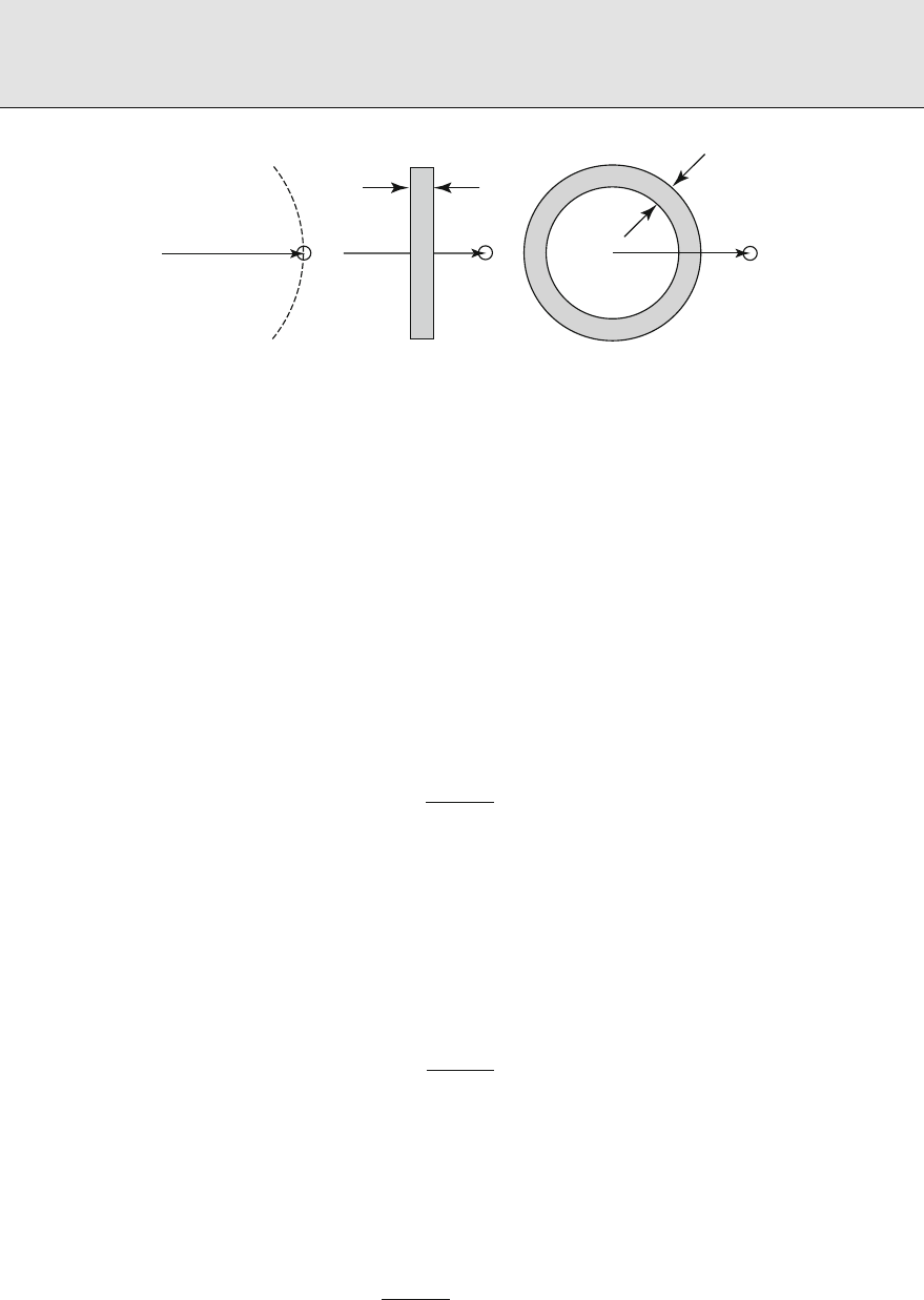
Radiation Shielding and Radiological Protection
* *
S
p
r
P
S
p
P
r
*
S
p
P
r
t
t
abc
⊡ Figure
Point isotropic source (a) in a vacuum, (b) with a slab shield, and (c) with a spherical-shell shield.
Point P is the location of the receiver or point detector
Notice that the dose and uence decrease as r
as the distance from the source is increased.
is decreasing dose with increasing distance is sometimes referred to as geometric attenuation.
Point Source in a Homogenous Attenuating Medium
Now consider the same point monoenergetic isotropic source embedded in an innite homoge-
nous medium characterized by a total interaction coecient μ.Asthesourceparticlesstream
radially outward, some interact before they reach the imaginary sphere of radius r and do not
contribute to the uncollided uence. e number of source particles that travel at least a distance
r without interaction is S
p
e
−μr
, so that the uncollided dose is
D
o
(r)=
S
p
R(E)
πr
e
−μ(E)r
.()
e term e
−μr
is referred to as the material attenuation term to distinguish it from the r
geometric attenuation term.
Point Source with a Shield
Now suppose that the only attenuating material separating the source and the detector is a slab
of material with attenuation coecient μ and thickness t as shown in
> Fig. b.Inthiscase,
the probability that a source particle reaches the detector without interaction is e
−μt
, so that the
uncollided dose is
D
o
(r)=
S
p
R(E)
πr
e
−μ(E)t
.()
is same result holds if the attenuating medium has any shape (e.g., a spherical shell of thick-
ness t as shown in
> Fig. c) provided that a ray drawn from the source to the detector passes
through a thickness t of the attenuating material.
If the interposing shield is composed of a series of dierent materials such that an uncollided
particle must penetrate a series of thicknesses t
i
of materials with attenuation coecients μ
i
before reaching the detector, the uncollided dose is
D
o
(r)=
S
p
R(E)
πr
exp(−
∑
i
μ
i
(E)t
i
).()

Radiation Shielding and Radiological Protection
Here
∑
i
μ
i
t
i
is the total number of mean-free-path lengths of attenuating material that an
uncollided particle must traverse without interaction, and exp(−
∑
i
μ
i
t
i
)is the probability that
a source particle traverses this number of mean-free-path lengths without interaction.
. Uncollided Doses for Distributed Sources
.. The Superposition Procedure
e results for the uncollided dose from a point source can be used to derive expressions for
the uncollided dose arising from a wide variety of distributed sources such as line sources,
area sources, and volumetric sources. One widely used approach is to divide the distributed
source conceptually into a set of equivalent point sources and then to sum (integrate) the dose
contribution from each point source.
e examples presented later for a line source are selected because of their simplicity or
utility. In all these examples, it is assumed that the source is monoenergetic and isotropic and
the detector is a point isotropic one. For polyenergetic sources, the monoenergetic result can
be summed (or integrated) over all source energies.
e superposition technique of decomposing a source into a set of simpler sources is very
powerful and has been applied to line, surface, and volumetric sources of complex shapes. Many
important practical cases have been examined and generalized results have been published.
Among the special cases are cylindrical and spherical surface and volume sources, with and
without external shields, and with interior as well as exterior receptor locations. e examples
below are but a few of the known results. For other source and shield congurations, the reader is
referred to the publications of Rockwell (), Blizard and Abbott (), Hungerford (),
Blizard et al. (), Schaeer (), Courtney (), Chilton et al. (), and Shultis and
Faw ().
.. Example Calculations for Distributed Sources
The Line Source
A straight-line source of length L emitting isotropically S
l
particles per unit length at energy
E is depicted in
> Fig. . A detector is positioned at point P,adistanceh from the source
along a perpendicular to one end of the line. Consider a segment of the line source between
distance x and x +dx measured from the bottom of the source. e source within this segment
may be treated as an eective point isotropic source emitting S
l
dx particles which produces an
uncollided dose at P of dD
o
. To obtain the total dose at P from all segments of the line source,
one then must sum, or rather integrate, dD
o
over all line segments. Several cases are discussed
as follows.
Line Source in a Nonattenuating Medium. In the absence of material interaction (> Fig. a),
the dierential uncollided dose produced by particles emitted in dx about x is, from (),
dD
o
(P)=
π
S
l
Rdx
x
+h
()

Radiation Shielding and Radiological Protection
θ
θ
O
P
0
L
x+dx
x
q
q
O
P
0
L
x+dx
x
h
h
t
ab
⊡ Figure
Isotropic line source (a) in a homogenous medium and (b) with a slab shield
and thus,
D
o
(P)=
S
l
R
π
L
dx
x
+h
=
S
l
Rθ
o
πh
.()
e angle θ
o
=tan
−
Lh in this result must be expressed in radians.
Line Source in a Homogenous Attenuating Medium. Now suppose that the source and receptor
are present in a homogenous medium with a total interaction coecient μ. Attenuation along
the ray from x to P reduces the uncollided dose at P to
dD
o
(P)=
π
S
l
Rdx
x
+h
exp−μ
√
x
+h
,()
where Rand μ generally depend on the particle energy E. e total uncollided dose now is
described by the integral
D
o
(P)=
S
l
R
πh
θ
o
dθ e
−μh sec θ
.()
is integral cannot be evaluated analytically. However, it can be expressed in terms of the
Sievert integral or the secant integral,denedas
F(θ, b)≡
θ
dx e
−b sec x
.()
is integral is widely available in the previously cited text and reference works. With it, the
dose from a line source may be expressed as
D
o
(P)=
S
l
R
πh
F(θ
o
, μh).()

Radiation Shielding and Radiological Protection
Line Source Behind a Slab Shield. Now suppose that the only material separating the line source
and the receptor is a parallel slab or concentric cylindrical-shell shield of thickness t and total
attenuation coecient μ
s
,asshownin > Fig. b. For this case, the analysis above using only
attenuation in the slab yields
D
o
(P)=
S
l
R
πh
F(θ
o
, μ
s
t).()
If the shield is made up of layers of thicknesses t
i
and attenuation coecients μ
si
,thenμ
s
t must
be replaced by
∑
i
μ
si
t
i
, the total mean-free-path thickness of the shield.
A Superposition Procedure for Line Sources. e restriction in the foregoing examples that the
detector be perpendicularly opposite one end of the line source is easily relaxed by use of the
principle of superposition of sources.
> Figure illustrates two receptor points in relation to
a line source in a homogenous attenuating medium. Determination of the uncollided dose at
either point may be obtained by conceptually decomposing the line source into two adjacent
line sources each of which has an end perpendicular to the detector. Point P
, for example, is
on a normal from the end of a projection of the line source. Were the line source truly of the
extended length, then the dose would be given by () with angle argument θ
.However,that
result would be too high by just the amount contributed by a line source of the same strength
subtending angle θ
.us,atpointP
,
D
o
(P
)=
S
l
R
πh
[F(θ
, μh)−F(θ
, μh)].()
By similar reasoning, at point P
,
D
o
(P
)=
S
l
R
πh
[F(θ
, μh)+F(θ
, μh)].()
As illustrated by these line source examples, the superposition of multiple distributed
sources, for each of which the dose is readily calculated, to create a more complex source con-
guration is an extremely useful procedure that can be used eectively for all types of sources.
P
1
P
2
h
S
L
q
4
q
1
q
2
q
3
⊡ Figure
Application of the superposition principle to an isotropic line source

Radiation Shielding and Radiological Protection
Indeed, part of the art of shield analysis is to devise how to reduce a complex source problem
to a set of simpler problems, and the source superposition principle is a valuable tool in this
reduction.
Photon Attenuation Calculations
is section describes the engineering methodology that has evolved for the design and anal-
ysis of shielding for gamma and X-rays with energies from about keV to about MeV. To
support this methodology, very precise radiation transport calculations have been applied to
a wide range of carefully prescribed situations. e results are in the form of buildup factors,
attenuation factors, albedos or reection factors, and line-beam response functions.
Buildup factors relate the total dose to the dose from uncollided photons alone and are most
applicable to point monoenergetic-radiation sources with shielding well distributed between
the source point and points of interest. Attenuation factors apply equally well to monoener-
getic sources and to polyenergetic sources such as X-ray machines and are most applicable
when a shield wall separates the source and points of interest, the wall being suciently far
from the source that radiation strikes it as a nearly parallel beam. ere are many common fea-
tures of buildup and attenuation factors and it is possible to represent one factor in terms of
the other. Albedos, which describes how radiation is reected from a surface, and line-beam
response functions, which are used in skyshine analyses, are taken up in other sections of this
chapter.
Discussed rst in this section are buildup factors for point isotropic and monoenergetic
sources in innite media. Incorporation of these buildup factors into the uncollided point kernel
is treated next. en addressed are three topics associated with the use of buildup factors. e
rst is the use of empirical buildup-factor approximations designed to simplify engineering
design and analysis. e second is the use of buildup factors with point kernels to treat spatially
distributed radiation sources. e third is the application of approximate methods to permit
the use of buildup factors in media with variations in composition.
. The Photon Buildup-Factor Concept
Whatever the photon source and the attenuating medium, the energy spectrum of the total
photon uence Φ(r, E)at some point of interest r may be divided into two components. e
unscattered component Φ
o
(r, E)consists of just those photons that have reached r from the
source without having experienced any interactions in the attenuating medium. e scattered
component Φ
s
(r, E)consists of source photons scattered one or more times, as well as sec-
ondary photons such as X-rays and annihilation gamma rays. Accordingly, the dose or detector
response D(r)at point of interest r may be divided into unscattered (primary) and scattered
(secondary) components D
o
(r)and D
s
(r).ebuildupfactorB(r)is dened as the ratio of
the total dose to the unscattered dose, i.e.,
B(r)≡
D(r)
D
o
(r)
= +
D
s
(r)
D
o
(r)
.()

Radiation Shielding and Radiological Protection
e doses may be evaluated using response functions described in > Sect. ,sothat
B(r)= +
∫
dE R(E)Φ
s
(r, E)
∫
dE R(E)Φ
o
(r, E)
,()
in which the integrations are over all possible E.
It is very important to recognize that in (), the uence terms depend only on the source
and medium, and not on the type of dose or response. e conversion factors or response func-
tion R(E)depends only on the type of dose, and not on the attenuating medium. For these
reasons, it is imperative to associate with buildup factors the nature of the source, the nature of
the attenuating medium, and the nature of the response.
When the source is monoenergetic, with energy E
o
,thenΦ
o
(r, E)=Φ
o
(r)δ(E −E
o
),
so that
B(r)= +
Φ
o
(r)
E
o
dE
R(E)
R(E
o
)
Φ
s
(r, E).()
In this case, the response nature is fully accounted for in the ratio R(E)R(E
o
).
. Isotropic, Monoenergetic Sources in Infinite Media
By far, the largest body of buildup-factor data is for point, isotropic, and monoenergetic sources
of photons in innite homogenous media. e earliest data (Fano et al. ; Goldstein ;
Goldstein and Wilkins ) were based on moments-method calculations (Shultis and Faw
) and accounted only for buildup of Compton-scattered photons. Subsequent moments-
method calculations (Eisenhauer and Simmons ; Chilton et al. ) accounted for buildup
of annihilation photons as well. Buildup-factor calculations using the discrete-ordinates ASFIT
code (Subbaiah et al. ) and the integral-transport PALLAS code (Takeuchi, Tanaka, and
Kinno ) account for not only Compton-scattered and annihilation photons, but also for u-
orescence and bremsstrahlung. ese calculations, which supplement later moments-method
calculations, are the basis for the data prescribed in the American National Standard for buildup
factors (ANSI/ANS ). Calculation of buildup factors for high-energy photons requires con-
sideration of the paths traveled by positrons from their creation until their annihilation. Such
calculations have been performed by Hirayama () and by Faw and Shultis (a) for photon
energies as great as MeV. Most point-source buildup-factor compilations exclude coher-
ently scattered photons and treat Compton scattering in the free-electron approximation. is
is also true for the buildup factors in the standard. us, in computing the dose or response
from unscattered photons, coherent scattering should be excluded and the total Klein–Nishina
cross section should be used. Correction for coherent scattering, signicant for only low-energy
photons at deep penetration, is discussed in ANSI/ANS ().
> Figure gives a qualitative impression of the buildup of secondary photons during the
attenuation of primary photons. For -MeV photons in lead, there is considerable buildup of
annihilation photons, which are emitted isotropically, and bremsstrahlung, which deviates little
in direction from the path of the decelerating electron or positron. For -MeV photons in lead,
there is very little buildup of secondary photons, owing to the strong photoelectric absorption
of the primary photons. In water, both - and -MeV photons experience Compton scattering
principally. However, for the higher-energy primary photons, the scattering leads to relatively
small change in direction.
> Figure illustrates the energy spectrum of the energy uence
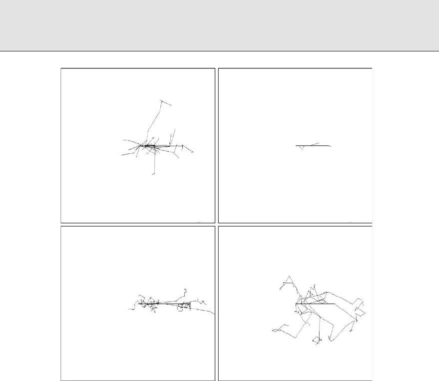
Radiation Shielding and Radiological Protection
10-MeV photons in lead
1-MeV photons in lead
10-MeV photons in water
1-MeV photons in water
⊡ Figure
Comparison of photon transport in lead and water. Each box has mean-free paths on a side.
Each depicts the projection in a plane of primary and secondary photon tracks arising from pri-
mary photons originating at the box center, moving to the right in the plane of the paper. Tracks
computed using the EGS code, courtesy of Robert Stewart, Kansas State University
EΦ(E)of reected and transmitted photons produced by -MeV primary photons, normally
incident on a concrete slab two mean free paths in thickness. ese uences are normalized to
unit incident ow and, thus, are dimensionless. Note that transmitted photons have energies up
to the energy of the primary photons. However, the reected photons, mostly single scattered,
aremuchmorerestrictedinenergy.
Tables of buildup factors are available in standards (ANSI/ANS ), the technical litera-
ture (Eisenhauer and Simmons ; Takeuchi and Tanaka ; Goldstein and Wilkins )
and many textbooks. Buildup-factor data are generally more broadly applicable than might be
thoughtatrstglance.Asindicatedin(), it is the ratio R(E)R(E
o
)that denes the depen-
dence of the buildup factor on the type of dose or response. For responses such as kerma or
absorbed dose in air or water, exposure, or dose equivalent, the ratio is not very sensitive to the
type of response. us, buildup factors for air kerma may be used with little error for exposure
or dose equivalent.

Radiation Shielding and Radiological Protection
0.0
0.0
0.10
0.20
0.30
0.50 1.0 2.01.5
Energy (MeV)
Transmitted
Reflected
Energy fluence energy spectrum
⊡ Figure
Transmitted and reflected energy fluences for -MeV photons normally incident on a concrete slab
of two mean free path thickness
It can be shown that, for a point isotropic source of monoenergetic photons in an innite
homogenous medium, the buildup factor depends spatially only on the number of mean free
paths μr separating the source and the point of interest. Here, μ is the total interaction coe-
cient (excluding coherent scattering) in the attenuating medium at the source energy, namely
μ(E
o
).us,wewritethebuildupfactorasB(μr), but it must be recognized that there is an
implicit dependence on the source energy, the nature of the attenuating medium, and the nature
of the response.
> Figure illustrates the buildup factor for concrete, plotted with the photon energy as
the independent variable and the number of mean free paths as a parameter. at there are
maxima in the curves is due to the relative importance of the photoelectric eect, as com-
pared to Compton scattering, in the attenuation of lower-energy photons and to the very low
uorescence yields exhibited by the low-Z constituents of concrete.
> Figure illustrates the
buildup factor for lead, plotted with the number of mean free paths as the independent vari-
able and the photon energy as a parameter. For high-energy photons, pair production is the
dominant attenuation mechanism in lead, the cross section exceeding that for Compton scat-
tering at energies above about MeV. e buildup is relatively large because of the production
of .-MeV annihilation gamma rays. As may also be seen from the gure, the attenuation
factor increases greatly at photon energies just above the .-MeV K-edge for photoelectric
absorption, each absorption resulting in a cascade of X-rays. For these reasons, buildup factors
may be extraordinarily large, as evidenced by the line for .-MeV photons in
> Fig. .
At energies below the K-edge, the buildup factors are very small. e importance of uores-
cence in the buildup of low-energy photons is addressed by Tanaka and Takeuchi () and by
Subbaiah and Natarajan ().
. Buildup Factors for Point and Plane Sources
Many so-called “point-kernel codes” nding wide use in radiation shielding design and anal-
ysis make exclusive use of buildup factors for point isotropic sources in innite media. is is
true even when the source and shield conguration is quite dierent from that of an innite
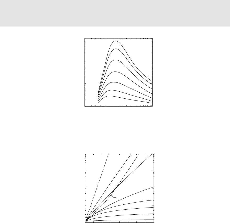
Radiation Shielding and Radiological Protection
10
–2
10
0
10
1
10
2
10
3
10
–1
10
0
10
1
Gamma-ray energy (Me)
Concrete
35 mean free paths
25
15
4
2
1
8
Exposure buildup factor
⊡ Figure
Air-kerma buildup factors for gamma-ray attenuation in concrete, excluding bremsstrahlung,
fluorescence, and coherent scattering. Data from Eisenhauer and Simmons ()
0
10
0
10
1
10
2
10
3
10
4
10 20 30 40
Mean free paths
Exposure buildup factor
0.2
0.5
1.0
2.0
5.0
0.13
10 MeV
15 MeV
0.089 MeV
⊡ Figure
Exposure buildup factors for gamma-ray attenuation in lead, calculated using the PALLAS code,
excluding coherent scattering. Data from ANSI/ANS ()
medium. A good example is that of a point source and point receptor, each at some distance in
air from an intervening shielding wall. Is the use of innite-medium buildup factors a conserva-
tive approximation? at question is addressed in
> Table , prepared for shielding of -MeV
gamma rays by iron. is table lists exposure buildup factors, in some cases for innite media
and in other cases for vacuum-bounded nite media. e rst column in the table is the num-
ber of mean free paths from source to receptor location. Six columns of buildup factors follow,
three for point isotropic (PTI) sources and three for plane monodirectional (PLM) sources.
e PTI source in an innite medium is the reference case. Data for the PTI source in a
nite medium refer to the exposure rate at the surface of a sphere whose radius corresponds to

Radiation Shielding and Radiological Protection
⊡ Table
Exposure buildup factors for -MeV gamma rays in iron
Source type and attenuating medium
Thickness
PTI PLM
(mfp)
Infinite
a
Finite
b
Slab
c
Infinite
d
Semi-infinite
e
Finite
f
. . . . .
. . . . . .
. . . . . .
. . . .
. . . . . .
. . . .
. . . . .
. . . . .
. . . .
. . . . .
. . . .
a
Standard ANSI/ANS-..-;
b
EGS calculations, courtesy Sherrill Shue, Kansas State University;
c
Dunn et al. ();
d
Goldstein ();
e
Takeuchi and Tanaka ();
f
Chen and Faw ()
the mean free path thickness. Data for the PTI source and slab shield are for a point source on
one side of a slab of given thickness and a receptor point directly on the opposite side of the
slab. Data for the PLM source in an innite medium are for the buildup factor as a function of
distance from a hypothetical plane source emitting a parallel beam of photons perpendicular
to the plane. Data for the PLM source in a semi-innite medium are for the buildup factor as a
function of depth in a half-space illuminated by a normally incident parallel beam of photons.
Data in the last column, for the PLM source in a nite medium, refer to the exposure on one side
of a slab shield of given thickness which is illuminated by a parallel beam of photons normally
incident on the opposite side of the slab.
It is apparent from
> Table that for the cases examined, use of buildup factors for point
sources in an innite medium, with few exceptions, is a conservative approximation in shield
design, that is, predicted doses are slightly higher than the actual doses. However, the PLM
examples are all for beams normally incident on slab shields. When beams are obliquely incident
on slab shields, point kernel codes routinely determine the number of mean free paths along
the oblique path through the slab shield and apply innite-medium buildup factors for the cor-
responding thickness. is practice can underestimate shielding requirements because buildup
factors for slant penetration of beams can greatly exceed those for point sources computed at
the same optical thicknesses (mean free paths) as is addressed later in this section.
Buildup factors are available for plane isotopic (PLI) and plane monodirectional (PLM)
gamma-ray sources in innite media. Indeed, Fano et al. (), Goldstein (), and Spencer

Radiation Shielding and Radiological Protection
(), in their moments-method calculations, obtained buildup factors for plane sources rst
and, from these, buildup factors for point sources. Buildup factors at depth in a half-space shield
are also available for the PLM source, that is, normally incident photons (Takeuchi et al. ;
Takeuchi and Tanaka ; Hirayama ).
Special methods have been developed for treating buildup when source and receptor are
separated by many shielding slabs, such as walls and oors of a structure, at various orientations.
For example, Dunn et al. () address shipboard radiation shielding problems and provide
buildup factors for common shielding materials.
.. Empirical Approximations for Buildup Factors
A great deal of eort has been directed toward the approximation of point-source buildup fac-
tors by mathematical functions which can be used directly in calculations. ese eorts have
dealt almost exclusively with buildup factors for point-isotropic and monoenergetic sources
in innite media. Two forms of approximation have been in use for many years. One is the
Taylor for m (Chilton ; Foderaro and Hall ; Shure and Wallace ). e other is the
Berger form (Chilton ; Chilton et al. ). While both forms still see a wide application in
computer codes used in engineering practice, a more modern, more accurate, but much more
complicated approximation is the geometric progression (GP) form, and without question it is
the preferred approximation to use if possible.
The Geometric Progression Approximation
An extraordinarily precise formulation, called the geometric progression approximation of the
buildup factor, was developed in recent years (Harima ; Harima et al. , ). e
approximation is in the form
B(E
o
, μr)
+(b −)(K
μr
−)(K −), K ≠
+(b −)μr, K =,
()
where
K(μr)=c(μr)
a
+d
tanh(μrξ −)−tanh(−)
−tanh(−)
,()
in which a, b, c, d,andξ are parameters dependent on the gamma-ray energy, the attenuating
medium, and the nature of the response. Example values of the parameters for kerma in air as
the response, and for attenuation in air, water, concrete, iron, and lead are listed in
> Tables
and
> . e parameters are based on PALLAS code calculations (Takeuchi et al. ).
.. Point-Kernel Applications of Buildup Factors
For a distributed source of monoenergetic photons S
v
(r
s
)of energy E
o
,thedosefromuncol-
lided photons at some position r is
D
o
(r)=
V
s
dV
s
S
v
(r
s
)R(E
o
)
πr
s
−r
e
−ℓ
,()

Radiation Shielding and Radiological Protection
⊡ Table
Coefficients for the geometric progression form of the gamma-ray buildup factor
Air kerma / air medium Air kerma / concrete medium
b c a ξ d b c a ξ d
Photon
energy
(MeV)
. . . . . −. . . . . −.
. . . . . −. . . . . −.
. . . . . −. . . . . −.
. . . −. . −. . . . . −.
. . . −. . . . . . . −.
. . . −. . . . . . . −.
. . . −. . . . . . . −.
. . . −. . . . . . . −.
. . . −. . . . . −. . −.
. . . −. . . . . −. . .
. . . −. . . . . −. . .
. . . −. . . . . −. . .
. . . −. . . . . −. . .
. . . −. . . . . −. . .
. . . −. . . . . −. . .
. . . −. . . . . −. . .
. . . −. . . . . −. . .
. . . −. . . . . −. . .
. . . −. . . . . −. . −.
. . . . . −. . . . . −.
. . . . . −. . . . . −.
. . . . . −. . . . . −.
. . . . . −. . . . . −.
. . . . . −. . . . . −.
. . . . . −. . . . . −.
Source: Extracted from American National Standard ANSI/ANS-..-, Gamma-Ray Attenuation
Coefficients and Buildup Factors for Engineering Materials, published by the American Nuclear Soci-
ety. Data are also available from Data Library DLC-/ANS, issued by the Radiation Shielding
Information Center, Oak Ridge National Laboratory, Oak Ridge, TN

Radiation Shielding and Radiological Protection
⊡ Table
Coefficients for the geometric progression form of the gamma-ray buildup factor
Air kerma / iron medium Air kerma / lead medium
b c a ξ d b c a ξ d
Photon
energy
(MeV)
. . . −. . .
. . . . . −.
. . . . . −. . . . . −.
. . . . . −. . . . . −.
. . . . . −. . . . . −.
. . . . . −. . . . . −.
. . . . . −. . . . . −.
. . . . . −.
. . . . . −.
. . . . . −.
. . . . . −. . . . . −.
. . . . . −.
. . . . . −.
. . . . . −.
. . . . . −.
. . . . . −. . . . . −.
. . . . . −.
. . . . . −. . . . . − .
. . . −. . −. . . . . −.
. . . −. . −. . . . . −.
. . . −. . −. . . . . −.
. . . −. . −. . . . . −.
. . . −. . −. . . . . −.
. . . −. . . . . . . −.
. . . −. . . . . . . −.
. . . −. . −. . . . . −.
. . . −. . − . . . . . −.
. . . . . −. . . . . −.
. . . . . −. . . . . −.

Radiation Shielding and Radiological Protection
⊡ Table (continued)
Air kerma / iron medium Air kerma / lead medium
b c a ξ d b c a ξ d
Photon
energy
(MeV)
. . . . . − . . . . . −.
. . . . . −. . . . . −.
. . . . . −. . . . . −.
. . . . . −. . . . . −.
Source: Extracted from American National Standard ANSI/ANS-..-, Gamma-Ray Attenuation Coefficients
and Buildup Factors for Engineering Materials, published by the American Nuclear Society. Data are also avail-
able from Data Library DLC-/ANS, issued by the Radiation Shielding Information Center, Oak Ridge
National Laboratory, Oak Ridge, TN
where the integration is over all source locations and ℓ is the optical thickness between
r
s
and r,namely,
ℓ =
∣r
s
−r∣
ds μ(s),()
with s measured along a straight line from r
s
to r. To correct for the buildup of secondary radi-
ation, an appropriate buildup factor is included in the integrand of (). If an innite-medium,
point-source buildup factor is used and the medium is of uniform composition but possibly of
variable density, the total dose at r is
D(r)=
V
s
dV
s
S
v
(r
s
)R(E
o
)
πr
s
−r
B(E
o
, ℓ)e
−ℓ
≡
V
s
dV
s
S
v
(r
s
)G(r
s
, r).()
Here,
G(r
s
, r)≡
R(E
o
)
πr
s
−r
B(E
o
, ℓ)e
−ℓ
()
is the dose Green’s function or point kernel that gives the dose at r due to a photon emitted
isotropically at r
s
.
From this approximate result, it is seen that the total dose at r from radiation emitted
isotropically from r
s
depends only on the material properties along a line between r
s
and r and
on the distance r
s
−rbetween these two points. is approximation, based on the innite-
medium, point-source buildup factor, is sometimes called ray theory, indicative that the total
dose is determined simply by the material and distance along the ray joining the source and
detector points. In many situations, it is an excellent approximation and is widely used in photon
shielding calculations. To illustrate the use of ray theory, two examples are given as follows.
Line Source in an Infinite Attenuating Medium
With reference to > Fig. and (), one sees that the total dose at detector point P due to
photons arising from the dierential source length dx is
dD(P)=
R(E
o
)S
l
dx
π(x
+h
)
e
−μ
√
x
+h
B(E
o
, μ
√
x
+h
).()

Radiation Shielding and Radiological Protection
In analogy to (), the response due to the entire line source is given by the integral
D(P)=R(E
o
)
S
l
πh
θ
o
dθ e
−μh sec θ
B(E
o
, μh sec θ).()
In general, the integral must be evaluated numerically. However, if the Taylor form of buildup-
factor approximation is employed, the integral yields a sum of Sievert integrals (Shultis and Faw
).
. Buildup Factors for Heterogenous Media
.. Boundary Effects in Finite Media
Consider a point isotropic source at the center of a nite sphere of shielding material and a dose
point at the surface. e sphere is surrounded by air, which may be approximated as a vacuum.
e use of an innite-medium buildup factor in calculating the dose at the boundary leads to an
overestimatebecause, in fact, no photons are reected back to the sphere from the space beyond
the spherical surface. Because the error is on the side of overestimation of the dose, corrections
are very oen ignored.
> Figure illustrates the magnitude of the eect of a vacuum interface for a tissue
medium. e lower bounding dashed lines are buildup factors for the dose at the surface of
a sphere of given radius. e upper bounding solid lines are for the dose at the same radius in
an innite medium. e intervening lines are for points interior to the nite sphere. It is appar-
ent that the eect of the boundary is insignicant for points more than about one mean free
path from the surface. Buildup factors at vacuum boundaries of nite media are conveniently
presented as the ratio (B
x
−)(B
∞
−),inwhichB
x
is the nite-medium buildup factor and
B
∞
is the innite-medium buildup factor. is ratio, which is illustrated in > Fig. ,canbe
used in many applications, because it has been found to be insensitive to whether the source is
a point isotropic, plane isotropic, or plane perpendicular, and to the distance x from the source
to the boundary.
Consider the same point isotropic source at the center of a nite sphere of shielding material
and a dose point at the surface. e sphere is bounded not by a vacuum but by a tissue medium.
is model is appropriate for determination of the phantom dose outside a shielding structure.
For use in such calculations, Gopinath et al. () determined adjustment factors to be applied
to innite-medium buildup factors. e adjustment factors, which are listed in
> Table ,
were adopted in the ANSI/ANS Standard () for buildup factors. ey were computed for
parallel beam sources normally incident on shielding slabs, but may be used for point sources as
well. e adjustment factor is to be used as follows. For the given shield material, rst compute
the absorbed dose in tissue at the location of the interface but within an innite medium of
the shielding material. en multiply the result by the adjustment factor to yield the maximum
absorbed dose in the tissue medium surrounding the shielding medium. e adjustment factor
is insensitive to the thickness of the shielding medium.

Radiation Shielding and Radiological Protection
0
0
0
20
40
1
2
2
3
3
4
4
0
100
200
300
400
246
6
7
8
9
10
5
81012
Mean-free-paths penetration
Buildup factor
At boundary of
finite medium
Within infinite
medium
⊡ Figure
Finite-medium versus infinite-medium buildup factors for a .-MeV point isotropic gamma-ray
source in tissue. Calculations performed using the EGS code, courtesy of Sherrill Shue (),
Kansas State University
.. Treatment of Stratified Media
e use of the buildup-factor concept for heterogenous media is of dubious merit, for the
most part. Nevertheless, implementation of point-kernel codes for shielding design and analysis
demands some way of treating buildup when the path from source point to dose point is through
more than one shielding material. Certain regularities do exist, however, which permit at least
an approximate use of homogenous-medium buildup factors for stratied shields. In general,
though, the user of a point-kernel code must make the choice of a single material to characterize
buildup. at choice is usually either the material with the greatest number of mean free paths
between the source and the receiver or the material nearest the receiver.
For hand calculations, greater exibility may oen be used. For example, consider two-
layer shields of optical thicknesses (mean free paths) ℓ
and ℓ
and eective atomic numbers Z
and Z
, numbered in the direction from source to detector. A commonly applied rule is that
if Z
<Z
, then the overall buildup factor is approximately equal to the buildup factor B
for
material evaluated at the total optical thickness ℓ
+ℓ
.However,ifZ
>Z
, then the overall
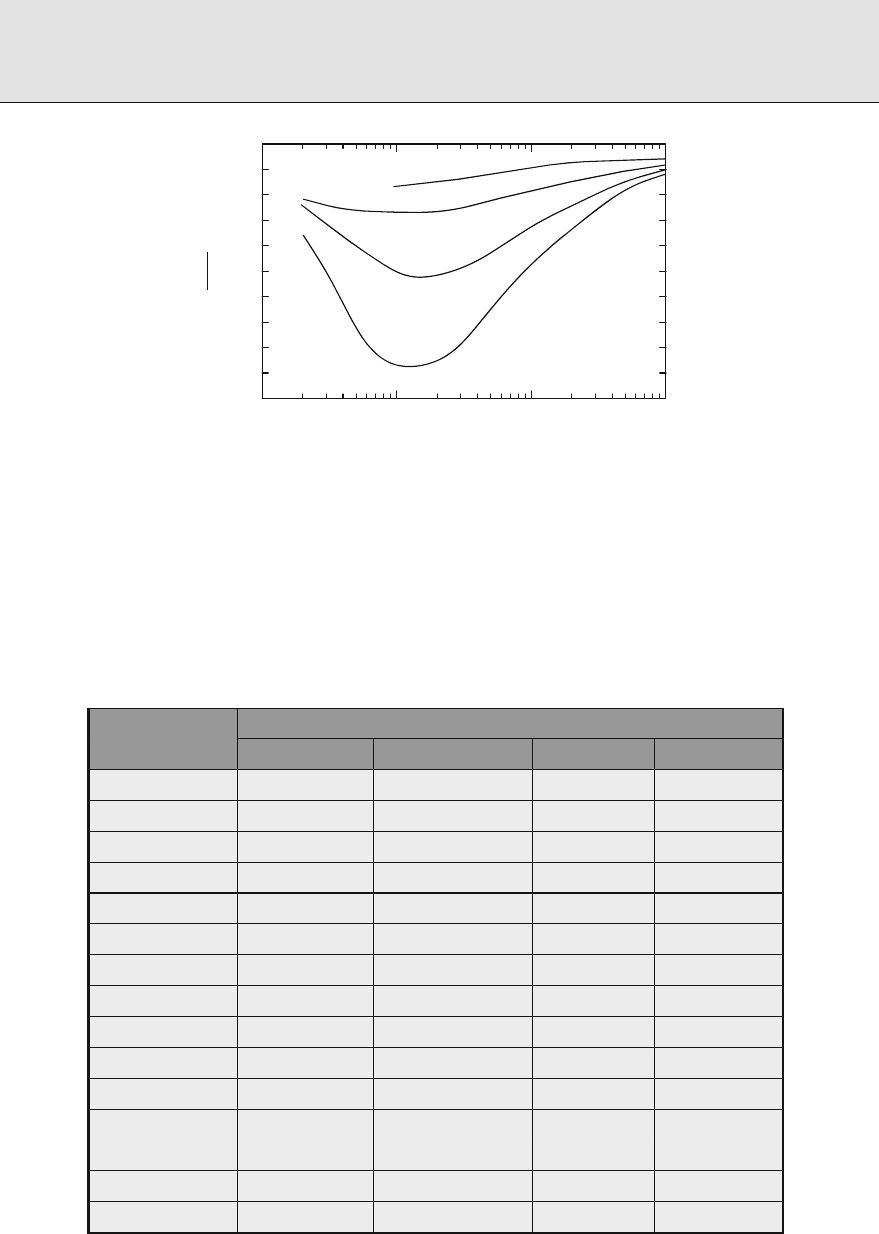
Radiation Shielding and Radiological Protection
10
–2
10
–1
10
0
10
1
0.5
0.6
0.7
0.8
0.9
1.0
E (MeV)
Water
Concrete
Iron
Lead
(B
x
–1)
B
∞
–1
⊡ Figure
Adjustment factor for the buildup factor at the boundary of a finite medium in terms of the infinite-
medium buildup factor for the same depth of penetration. Exposure buildup calculations were
performed for point isotropic sources in finite spheres and infinite media, using the EGS code,
courtesy of Sherrill Shue, Nuclear Engineering Department, Kansas State University
⊡ Table
Adjustment factors to be applied to infinite-medium buildup factors when the maximum dose
equivalent is to be evaluated in a thick-tissue medium bounding the shielding medium
Shielding medium
E (MeV) Water Concrete Iron Lead
. . . . .
. . . . .
. . . . .
. . . . .
. . . . .
. . . . .
. . . . .
. . . . .
. . . . .
. . . . .
. . . . .
. . . . .
. . . . .
. . . . .
. . . . .
Source: ANSI/ANS ()

Radiation Shielding and Radiological Protection
buildup factor is the product B
(ℓ
)×B
(ℓ
). More precise methods have been suggested by
Kalos (Goldstein ), Broder et al. (), Kitazume (), Bünemann and Richter (),
Harima (), Su and Jiang (), Harima and Hirayama (), and Shin and Hirayama
(, ).
. Broad-Beam Attenuation of Photons
.. Attenuation Factors for Photon Beams
It is oen the case in dealing with the shielding requirements for a radionuclide or X-ray source
that the source is located some distance in air from a wall or shielding slab, and the concern is
with the radiation dose on the exterior (cold) side of the wall. Oen too, the source is suciently
far from the wall that the radiation reaches the wall in nearly parallel rays, and the attenuation in
the air is quite negligible in comparison to that provided by the shielding wall. Shielding design
and analysis in the circumstances just described, and illustrated in
> Fig. , are addressed by
the National Council on Radiation Protection and Measurements (NCRP ) in their widely
used Report . Attenuation of photons from both monoenergetic and polyenergetic sources
can be established in terms of the formula
D(P)=D
o
(P)A
f
,()
in which D(P)isthedoseorresponseatpointP (the receiver in
> Fig. ), D
o
(P)is the
response in the absence of the shield wall, accounting only for the inverse-square attenuation,
and A
f
is an attenuation factor which depends on the nature and thickness of the shielding
material, the source energy characteristics, and the angle of incidence θ. e attenuation factor
incorporates the response function and combines buildup and exponential attenuation into a
single factor A
f
.
.. Attenuation of Oblique Beams of Photons
When monoenergetic beams of gamma rays are obliquely incident on shielding slabs,
attenuation-factor and conventional ray-theory methods are not successful. e reason is that
*
r
t
Source
Receiver
q
⊡ Figure
Attenuation of gamma and X-rays from a point source in air by a shielding wall

Radiation Shielding and Radiological Protection
the uncollided component of penetrating radiation is likely very small when compared with the
collided component, and that the collided component is likely only very weakly dependent on
the uncollided component. Obliquely incident beams, however, may be treated using a modi-
ed buildup factor that is a function of the angle of incidence. With respect to
> Fig. ,the
beam attenuation factor in ()maybewrittenas
A
f
=B(E
o
,cosθ, μt)e
−μt/cos θ
.()
Values of the special buildup factor B(E
o
,cosθ, μt)are available in Shultis and Faw () for
concrete, iron, and lead shields for thicknesses as great as mean free paths for wide ranges of
photon energy and angle of incidence. Attenuation factors for concrete are listed in
> Table .
Attenuation factors for other materials may be found in the standard ANSI/ANS-. ().
.. Attenuation Factors for X-Ray Beams
e appropriate measure of source strength for X-ray sources is the electron-beam current, and
the appropriate characterization of photon energies, in principle, involves the peak accelerat-
ing voltage (kVp), the wave form, and the degree of ltration (e.g., mm Al) through which the
X rays pass. Although the degree of ltration of the X rays would aect their energy spectra,
there is only a limited range of ltrations practical for any one voltage, and within that limited
range, the degree of ltration has little eect on the attenuation factor (NCRP ). Most diag-
nostic radiographic procedures for adult patients are conducted with an X-ray-beam quality of
– mm Al half-value-layer (HVL) (Keriakes and Rosenstein ), which is consistent with
.–. mm Al ltration of the X-ray source. e National Council on Radiation Protection
and Measurements (NCRP ) requires at least . mm HVL and . mm Al ltration for
three-phase generators with voltages kVp or greater. Similar requirements are stated for
lower voltages and for single-phase generators. Data on energy spectra from a wide variety
of X-ray tubes and ltrations are available (Fewell and Shuping ; Fewell et al. ). For a
given voltage, the greatest penetration would occur for a constant potential generator, but it
has been found that X rays from modern three-phase generators are very nearly as penetrating
(Simpkin ; Archer et al. ). Less penetrating are X rays from single-phase generators.
Conservatism in design, allowing for upgrade in generators, dictates use of attenuation data for
multiphase or constant-potential generators. If i is the beam current (mA) and r is the source–
detector distance (m),then(), with dose rate (cGy min
−
Rmin
−
)as the response, takes
the form
˙
D(P)=
i
r
K
o
A
f
,()
in which K
o
is the radiation output factor with units of dose rate in vacuum (or air), per unit
beam current at a distance of m from the source in the absence of any shield. e dose unit was
recently changed from exposure to air kerma (NCRP ). For the same voltage, the radiation
output factor for a single-phase generator is less than that for a three-phase generator by a factor
of
√
(NCRP).
Attenuation factors for X rays normally incident on various shielding materials have been
t by Simpkin (, ) and by Archer et al. () to the following expression, which was

Radiation Shielding and Radiological Protection
⊡ Table
Attenuation factors for monoenergetic beams of gamma rays obliquely incident on slabs of
ordinary concrete, expressed as the ratio of transmitted to incident air kerma
Photon
energy
Slab
thickness cos θ
(MeV) (mfp) . . . . . . .
. .E- .E- .E- .E- .E- .E- .E-
.E- .E- .E- .E- .E- .E- .E-
.E- .E- .E- .E- .E- .E- .E-
.E- .E- .E- .E- .E- .E- .E-
. .E- .E- .E- .E- .E- .E- .E-
.E- .E- .E- .E- .E- .E- .E-
.E- .E- .E- .E- .E- .E- .E-
.E- .E- .E- .E- .E- .E- .E-
. .E- .E- .E- .E- .E- .E- .E-
.E- .E- .E- .E- .E- .E- .E-
.E- .E- .E- .E- .E- .E- .E-
.E- .E- .E- .E- .E- .E- .E-
. .E- .E- .E- .E- .E- .E- .E-
.E- .E- .E- .E- .E- .E- .E-
.E- .E- .E- .E- .E- .E- .E-
.E- .E- .E- .E- .E- .E- .E-
. .E- .E- .E- .E- .E- .E- .E-
.E- .E- .E- .E- .E- .E- .E-
.E- .E- .E- .E- .E- .E- .E-
.E- .E- .E- .E- .E- .E- .E-
.E- .E- .E- .E- .E- .E- .E-
.E- .E- .E- .E- .E- .E- .E-
.E- .E- .E- .E- .E- .E- .E-
.E- .E- .E- .E- .E- .E- .E-
Source: MCNP calculations extending the work of Fournie and Chilton () and Chen and Faw ()

Radiation Shielding and Radiological Protection
originally recommended by Archer, ornby, and Bushong ():
A
f
= +
β
α
e
αγx
−
β
α
−/γ
,()
in which x is the material thickness, in units of millimeters. e coecients for lead and con-
crete attenuation factors are listed in
> Table based on measurements and calculations of
Archer et al. (), Simpkin (a), and Légaré et al. (). Conservative values of the output
factor K
o
given in the table conform to those given by Keriakes and Rosenstein () and in
NCRP Report ().
In the design and analysis of shield walls for X-ray installations, it is necessary to account
for a number of factors: () the maximum permissible dose for an individual situated beyond
the shield wall during some prescribed time interval, such as week, () the workload,which
is the cumulative sum during the prescribed time interval of the product of the beam current
and the duration of machine operation, () the use factor, which is the fraction of machine
operation time that the X-ray beam is directed toward the shield wall, and () the occupancy
factor, which is the fraction of the time during which the X-ray machine is in use and the beam is
directed toward the shield wall behind which the individual at risk is actually present. All these
factors are taken into account in the methodology of NCRP Reports and . In addition, that
methodology also treats leakage radiation from the X-ray machine and radiation scattered from
patients or other objects present in the X-ray beam. e methodology is discussed at length by
Simpkin (a,b, , ) and by Chilton et al. (). A computer code for routine X-ray-
shielding design and analysis [Simpkin a] is available as code packages CCC-/KUX and
CCC-/CALKUX from the Radiation Safety Information Computational Center, Oak Ridge
National Laboratory, Oak Ridge, Tennessee.
⊡ Table
Fitting parameters for constant-potential X-ray attenuation factors computed
for typical energy spectra from modern three-phase generators. The data for
and kV are for low-voltage units with molybdenum anodes and beryllium
windows. Otherwise, data are for tungsten anodes
kVcp K
o
a
α (mm
−
) β (mm
−
) γ α (mm
−
) β (mm
−
) γ
Lead, ρ = . g/cm
Concrete, ρ = . g/cm
. . . . . . .
. . . . . . .
. . . . . . .
. . . . . . .
. . . . . . .
. . . . . . .
. . . . . . .
a
Radiationoutputinunits(mGymA
−
min
−
at m).
Source: Parameters α, β, γ,andK
o
arefromNCRP();thoseforK
o
are based on data of Archer
et al. ()

Radiation Shielding and Radiological Protection
.. The Half-Value Thickness
e half-value thickness, or half-value layer (HVL), is dened in terms of the attenuation of a
parallel beam gamma or X rays, namely,
HVL(x)=
−ln
d ln A
f
(x)dx
.()
For the special case of uncollided monoenergetic photons, A
f
(x)=e
−μx
,and
HVL =
−ln
d ln A
f
dx
=
ln
μ
.()
However, when dealing with X rays or accounting for scattered gamma rays, the half-value
thickness is a function of the depth of penetration, namely,
HVL(x)=
−ln
d ln A
f
(x)dx
.()
At shallow penetrations, lower-energy photons are selectively removed and the HVL is relatively
small. As the beam spectrum “hardens” with increasing penetration, the HVL increases. As may
be shown from (), the following relationships apply to X-ray data t by that equation:
lim
x→
HVL =
ln
α +β
()
and
lim
x→∞
HVL =
ln
α
.()
One other important application of the HVL. Values of the HVL at shallow penetration,
usually for aluminum or copper, are widely used to characterize the penetration ability of
X rays and as a parameter in the assessment of radiation doses from medical X rays. HVL data
for a wide variety of materials and a wide variety of gamma- and X-ray source energies may be
foundinNCRPReportsand(,).
. Shield Heterogeneities
Occasionally, an analyst encounters a shield that includes regions of composition dierent from
the bulk shield material. ese regions may be large with a well-dened geometry, such as
embedded pipes or instrumentation channels transverse to the direction of radiation penetra-
tion. By contrast, there may be incorporated into the shield material small irregularly shaped
and randomly distributed voids or lumps of other material, such as pieces of scrap iron used to
increase the eectiveness of a concrete shield against gamma radiation. For a large, well-dened
heterogeneity in the shield (most oen a single void or region of low-interaction coecient), ray
theory can oen be used eectively. For simple geometry (e.g., a spherical or cylindrical void in
aslabshield),() can be evaluated analytically. Otherwise, numerical integration techniques
are used. Examples are given by Rockwell (), Burrus (b), and Chilton et al. ().

Radiation Shielding and Radiological Protection
Rigorous calculation of the eect of such heterogenous regions in a shield usually requires
Monte Carlo techniques. In this section, some simplied techniques, based on ray theory,
illustrate the eect of shield heterogeneities.
Consider two rays through a shield (see
> Fig. ) containing randomly distributed small
voids in a continuous phase which has an eective linear attenuation coecient μ.Raytravels
adistancet with transmission probability T
=e
−μt
.Raytravelsadistancet −δ with trans-
mission probability T
=e
−μ(t−δ)
. e average path length for these two rays is
¯
t =t −δ, and
the average transmission probability is
¯
T =
(T
+T
)=e
−μ
¯
t
cosh(μδ)>e
−μ
¯
t
.()
us, it is seen that the use of the average path length of a ray through the shield material
underpredicts the average transmission probability. If the voids are replaced by a material with
an attenuation coecient dierent from that of the shield material, a similar analysis shows that
use of the average path length (in mean free paths) also underestimates the average transmission
probability. is eect is known as channeling and its neglect leads to an overestimation of the
eectiveness of a shield. Channeling is seen in shields with randomly included heterogeneities
as well as in shields with well-dened placement of voids and heterogenous regions.
.. Limiting Case for Small Discontinuities
Suppose in ()thatδ << μ
−
, that is, the lumps or voids are much smaller in size than the
radiation mean free path length in the continuous phase. In this case, the channeling eect is
negligible, and shield transmission factors may be estimated using an average mass attenuation
coecient
μρ.Supposethatμ, ρ,andw are the eective linear attenuation coecient, density,
d
t
1
2
⊡ Figure
Shield containing randomly distributed voids

Radiation Shielding and Radiological Protection
and weight fraction of the continuous phase, and μ
′
, ρ
′
,andw
′
are the same quantities for the
discontinuous phase. If v is the volume fraction of the voids or lumps in the shield and
¯
ρ is the
average shield density, the average mass attenuation coecient is
μρ =ω
μ
ρ
+ω
′
μ
′
ρ
′
=
ρ( −v)
¯
ρ
μ
ρ
+
ρ
′
v
¯
ρ
μ
′
ρ
′
,()
and the transmission probability is thus
T(t)=e
−(μ/ρ)
¯
ρt
=e
−[(−ν)μ+νμ
′
]t
=e
−μt
e
−(μ
′
−μ)νt
.()
is transmission probability is the same as if the shield materials (continuous and discontin-
uous components) were conceptually homogenized and the average attenuation coecient for
the homogenous mixture was used.
.. Small Randomly Distributed Discontinuities
Channeling eects have been treated by a statistical technique attributed to Coveyou (Burrus
a). Consider an innite slab shield of thickness t, uniformly and normally illuminated on
one side by radiation. e shield contains randomly distributed lumps with a dierent linear
attenuation coecient (μ
′
) from that of the shield material (μ). Suppose that the mean chord
length through a lump is δ.enitcanbeshownthat
T(t)=e
−μt
e
−(μ
′
−μ)νt/c
o
.()
Here, c
o
is the cross-section eectiveness ratio,namely,
c
o
=
−(μ
′
−μ)νδ
ln[( −ν)+νe
−(μ
′
−μ)δ
]
.()
For an arbitrary convex lump, the mean chord length is just four times the volume/surface area
ratio. For concave and irregularly shaped lumps, the value of δ must be determined by specic
calculation or by measurement of slices of the shield material.
Neutron Shielding
Neutron shielding analysis is oen quite complex, involving not only attenuation of primary
or source neutrons but also production and attenuation of secondary particles. ese associ-
ated problems include the production of photons from neutron inelastic scattering, slowing
down and thermalization of neutrons, capture of thermal neutrons leading to capture gamma
photons, and even production of secondary neutrons as a result of ssion or (n,n)reactions.
Moreover, none of these associated problems is accurately solved using elementary techniques.
To obtain accurate results with errors of only a few percentage, it is necessary to use sophisti-
cated numerical techniques based on the exact descriptions of photon and neutron transport
in the shield.

Radiation Shielding and Radiological Protection
In this section, several of the simplied techniques developed for neutron shielding over the
past years are reviewed. Although these techniques are seldom used directlyin modern shield
analysis, the ideas behind them provide an insight into important mechanisms that determine
the eectiveness of a neutron shield. Such insight allows the analyst to interpret and assess more
critically results obtained with large computer codes.
. Neutron Versus Photon Calculations
e development of simplied techniques for neutron shielding analysis is considerably more
dicult than for photon shielding. e use of buildup factors, while theoretically applicable to
any type of indirectly ionizing radiation, is much more dicult to apply to the neutron problem.
e buildup of scattered neutrons depends strongly on the isotopic composition of the medium,
on the neutron energy spectrum, and above all, on the problem geometry. Near a free surface,
neutron densities generally decrease much more dramatically than in the photon case. Conse-
quently, the use of innite-medium buildup factors, which work so well for photon analyses,
may introduce serious errors for neutron analyses.
Another serious dierence between photon and neutron calculations arises from the
evolution of thinking about uence-to-dose conversion coecients. Many dierent response-
function sets have been issued by various national and international institutions over the past
years. Because the photon quality factor is independent of the photon energy, the ratio of
dierent conversion coecients, except at very low energies, is nearly constant, as is seen in
> Fig. . us, measured or calculated photon doses based on one conversion coecient can
be converted easily to another type of dose by an appropriate multiplicative constant. By con-
trast, the many neutron response functions that have been used at one time or another are not
simply related to each other by a multiplicative constant (see, for example,
> Fig. ). us,
much neutron shielding data (e.g., point kernels, albedos, transmission factors, etc.) reported
in obsolete units cannot be rigorously used in modern shielding analysis. At best, only approxi-
mate conversions can be made; and if accurate results are needed, then there is no recourse but
to repeat the original calculations or measurements using modern dose units.
. Fission Neutron Attenuation by Hydrogen
ere is one widely encountered situation for which the attenuation of a fast-neutron beam
can be expected to be somewhat insensitive to the buildup of scattered neutrons. Elastic scat-
tering from light elements results in a signicant portion of the neutron’s kinetic energy being
lost, on the average, in a single scatter. In particular, for scattering from hydrogen the average
energy loss is one-half of the initial neutron energy and, consequently, the scattering of a fast
neutron on hydrogen acts essentially as an eective absorption or removal interaction because
the neutron is, on the average, removed from the fast-neutron energy region by a single scat-
ter. us, for the deep penetration of fast neutrons, the fast-neutron uence might be expected
to be very nearly equal to that of uncollided fast neutrons deep in an hydrogenous medium.
In addition, the cross section for hydrogen in the MeV-energy region increases as the neutron
energy decreases; hence, a low-energy neutron is much more likely to scatter from hydrogen
than is a high-energy neutron. In eect, this characteristic of the hydrogen cross section implies

Radiation Shielding and Radiological Protection
that, once a fast neutron interacts in an hydrogenous medium, the subsequent scattering or
slowing-down interactions occur relatively near the point of the rst scattering interaction.
From these arguments, it is then possible to derive a point kernel for the uncollided fast-
neutron uence in an innite hydrogenous medium (Albert and Welton ). Consider a
point-ssion source which emits S
p
ssion neutrons with an energy spectrum given by χ(E)
in an innite hydrogenous medium with a hydrogen atom density of N
H
cm
−
. e uncollided
uence Φ
o
H
(r, E)at distance r from the source, if one neglects any nonhydrogen collisions, is
Φ
o
H
(r, E)=
S
p
χ(E)
πr
exp[−N
H
σ
H
(E)r].()
Because the total fast-neutron uence is of interest, () must be integrated over all ssion
energies. To perform such an integration, the functional form of χ(E)and σ
H
(E)must be used,
and because the fast uence is dominated by those neutrons with energies greater that MeV,
a simpler form from that of () may be used, namely,
χ(E)Ae
−aE
,()
where the parameters A and a depend on the ssile isotope and the energy range of the t. For
the energy range – MeV, the hydrogen total cross section (which is essentially the scattering
cross section) may be approximated by (Blizard )
σ
H
(E)BE
−b
,()
where B =. ×
−
, b =., and σ
H
is in units of cm
when E is in units of MeV.
As is shown by Chilton, Shultis, and Faw (), integration of () over all energy yields
Φ
o
H
(r)=
S
p
Aβ
πr
r
γ/
exp(−αr
γ
),()
where
γ ≡( +b),()
β ≡
πγ(N
H
Bb)
γ
a
+γ
/
,()
and
α ≡
γ
a
b
bγ
(N
H
B)
γ
.()
e presence of heavier components in the attenuating medium (e.g., the oxygen in a water
shield) also degrades the fast neutrons in energy, although not nearly as well as the hydrogen.
Many experiments have been performed to measure the attenuation of fast ssion neutrons in
hydrogenous media. Experimentally, it is found that the fast-neutron uence falls o slightly
faster with increasing distance from the source than () would indicate. In particular, experi-
mental data for attenuation in water reveal that the spatial distribution of the total fast-neutron
uence can be related to that in hydrogen by
Φ
o
(r)=Φ
o
H
(r)exp(−μ
r,O
r);()

Radiation Shielding and Radiological Protection
that is, the nonhydrogen component (oxygen) contributes an exponential attenuation factor.
e constant μ
r,O
, although given the symbol of an attenuation coecient, is an empirically
derived constant to account for the nonhydrogen attenuation. Because of the similarity of this
constant to the coecient in the usual exponential attenuation of uncollided radiation, it is
called the removal coecient, although numerically it is usually signicantly less than the actual
total attenuation coecient. More is said in the next section about the physical basis of the
removal coecient. us, by correcting for the attenuation of the oxygen, the fast-neutron
uence in water for a point ssion source may be written as
Φ
o
(r)=
AβS
p
πr
r
γ/
exp(−αr
γ
−μ
r,O
r).()
It should be emphasized at this point that the fast-neutron uence kernel obtained from (),
with S
p
=, is not adequate for detector-response evaluation because no account is taken of the
buildup of small-angle-scattered neutrons which have lost very little energy. e usefulness of
the kernel, however, is to suggest how the uncollided uence (and hence, dose) can be expected
to vary with distance from the source. Consequently, by tting the functional form of the kernel
to experimental data, one could expect to obtain a reasonably accurate semiempirical result.
Such a tting technique could be expected to lead to better agreement with experiment because
the buildup of fast neutrons could be incorporated empirically. One widely used result is due to
Casper (), who obtained the following fast-neutron tissue-absorbed-dose kernel for a point
U ssion source in water:
𝒢(r)=
. ×
−
πr
r
.
exp(−.r
.
−.r),()
where r has units of centimeters and
𝒢 has units of Gy for a source strength of one ssion
neutron.
Other functional forms have been t to experimental dose data or to values calculated by the
more elaborate neutron transport techniques. One particularly simple form for a
U ssion
source, which can be readily incorporated into analytical kernel calculations, expresses the fast-
neutron tissue-absorbed dose kernel for water in terms of exponential functions (Grotenhuis
; Glasstone and Sesonske ), in the same units as used above, as
𝒢(r)=
−
πr
.e
−.r
+.e
−.r
.()
Another empirical result, with the same units, which ts the experimental water kernel for
absorbed dose in tissue more accurately than do the previous two results and which is valid over
amuchwiderrangeofr ( ≤r ≤ cm), is given by Brynjolfsson [] as
𝒢(r)=
. ×
−
πr
e
−br
,()
where
b =. −. r −
r
− +
r
−
.()
A comparison of the foregoing three empirical tissue-absorbed dose-point-kernels in water with
accurately calculated values is presented in
> Table .

Radiation Shielding and Radiological Protection
⊡ Table
Absorbed dose kernels in tissue from a point
U fission source
in water (
𝒢
o
) obtained by the moments method (Goldstein
)
Ratio to 𝒢
o
a
𝒢
/𝒢
o
𝒢
/𝒢
o
𝒢
/𝒢
Distance
from source
(cm)
πr
𝒢
o
(r)
moments methods
(Gy cm
)
. ×
−
. .
. ×
−
. . .
. ×
−
. . .
. ×
−
. . .
. ×
−
. . .
. ×
−
. . .
. ×
−
. . .
a
𝒢
calculated from (); 𝒢
calculated from (); and 𝒢
calculated
from ()
. Removal Cross Sections
In many realistic situations, ssion neutrons are attenuated not only by an hydrogenous medium
but also by an interposed nonhydrogenous shield such as the wall of a steel pressure vessel. Many
experimental data have been obtained for such situations; and under special circumstances,
the eect of the nonhydrogen component can be very simply accounted for by an exponen-
tial attenuation factor, much as was done for the oxygen correction examined in the preceding
section.
An idealized fast-neutron attenuation experiment is shown in
> Fig. . A point isotropic
ssion source in an innite homogenous hydrogenous medium is surrounded by a spherical
shell of thickness t composed of a nonhydrogenous material. Experimental results reveal that
under certain circumstances, the tissue-absorbed dose D
′
with the shell in position (i.e., at a
distance r
+r
of hydrogenous medium plus a thickness t of the nonhydrogenous component)
is related to the dose D at a distance r =r
+r
from the source, without the shell, by
D
′
=D
r
r +t
e
−μ
r
t
,()
where μ
r
is called the removal coecient and is a constant characteristic of the nonhydrogenous
component for a given ssion-neutron energy spectrum.
Two important restrictions on the experimental arrangement are required for the validity
of (). First, it is important that there be at least g cm
−
of hydrogen, equivalent to cm
of water, between the nonhydrogenous component and the observation position. Second, the
thickness t must be such that μ
r
t is less than about .
Although the factor exp(−μ
r
t)in () appears to indicate that absorption of neutrons
is taking place in the nonhydrogenous component, the principal interactions are scattering
interactions in which the ssion neutrons are degraded in energy only slightly. However, the

Radiation Shielding and Radiological Protection
Nonhydrogenous
shield
Detector
Point fission
source
t
r
1
r
2
o
⊡ Figure
Idealized experimental geometry for the measurement of the removal cross-section in which a
nonhydrogenous shield of thickness t is placed between the point-fission source and the detector
in an infinite hydrogenous medium
hydrogen in the material following the nonhydrogenous component (one of the two exper-
imental restrictions) moderates or removes the slightly slowed-down neutrons more quickly
than those neutrons which traverse the nonhydrogenous component without any energy loss.
If, following the nonhydrogenous component, there is sucient hydrogen to eect the removal
of the neutrons which are slightly moderated, the spatial variation of the fast-neutron tissue-
absorbed dose D can be obtained from one of the kernels of ()to(), for the case that the
hydrogenous medium is water.
If a series of dierent materials is inserted into the hydrogenous medium, the removal term
exp(−μ
r
t)of () becomes simply exp(−
∑
i
μ
r,i
t
i
),whereμ
r,i
is the removal coecient for
the ith slab of thickness t
i
. Similarly, if a slab of a mixture of elements is inserted, the removal
coecient μ
r
for the slab is given by
∑
i
N
i
σ
r,i
,whereN
i
is the atom density of the ith element
with microscopic removal cross section σ
r,i
. is additive nature of the relaxation lengths for the
nonhydrogen components, which is a direct consequence of (), has generally been supported
by experiment, although some deviations have been noted.
e (n, γ)absorption cross-section for most materials in the MeV-energy region is negli-
gible and plays no signicant role in the removal of fast neutrons. Conceptually, the removal
cross-section is that fraction of the total fast-neutron cross section, averaged over energies of
ssion neutrons, representing inelastic and elastic scattering through a large scattering angle
(i.e., scattering in which there is signicant energy loss). us, the removal cross section can
be expected to be somewhat less than the total cross section. As an approximation, μ
r
¯
μ
t
,
where
¯
μ
t
is the average total attenuation coecient in the energy range – MeV (Goldstein
and Aronson ).
ere is no rm theoretical reason for the removal cross section to be a material constant,
and indeed, it might be expected to vary with the ssion neutron energy spectrum, the thick-
ness of the nonhydrogenous shield, amount of hydrogenous material on either side of the slab,
and the geometry of the experiment. However, experimental results have shown that for most
situations (provided that the slab is less than ve removal relaxation lengths thick), μ
r
can oen
be taken as a constant for a given incident ssion spectrum. In
> Table , the measured values
of removal cross sections for several materials are presented. To obtain removal cross sections

Radiation Shielding and Radiological Protection
⊡ Table
Measured microscopic removal cross sections of various ele-
ments and compounds for
U fission neutrons
Material σ
r
(b/atom) Material σ
r
(b/atom)
Aluminum . ± . Oxygen . ± .
Beryllium . ± . Tungsten .
Bismuth . ± . Zirconium . ± .
Boron . ± . Uranium . ± .
Carbon . ± . Boric oxide, B
O
. ± .
a
Chlorine . ± . Boron carbide, B
C . ± .
a
Copper . ± . Fluorothene, C
F
Cl . ± .
Fluorine . ± . Heavy water, D
O . ± .
a
Iron . ± . Heavimet
b
. ± .
Lead . ± . Lithium fluoride, LiF . ± .
a
Lithium . ± . Oil, CH
group . ± .
a
Nickel . ± . Paraffin, C
H
. ± .
a
Removal cross-section is in barns per molecule or per group.
b
wt% W, wt% Ni, wt% Cu; cross-section is weighted average.
Source:Blizard();ChapmanandStorrs()
for other elements, the following empirical formulas (in units of cm
/g) have been obtained to
permit interpolation between these measured values (Zoller ):
μ
r
ρ
=
.Z
−.
Z ≤
.Z
−.
Z >
()
or
μ
r
ρ
=.A
−/
Z
−.
, ()
where A and Z are the atomic mass and atomic number, respectively, for the element of concern.
. Extensions of the Removal Cross Section Model
.. Effect of Hydrogen Following a Nonhydrogen Shield
In the preceding section, it was emphasized that the applicability of the removal cross section
model of () was dependent on whether there is sucient hydrogen following the nonhy-
drogenous component to complete the removal of neutrons which have been degraded slightly
in energy by the nonhydrogen component. If there is insucient hydrogen following the

Radiation Shielding and Radiological Protection
nonhydrogenous component, not all the neutrons are removed, and the removal cross-section
appears to have a smaller value. In such a situation, the removal cross-section is no longer
simply a material property, but it is also a function of the hydrogen thickness following the
nonhydrogen component (Shure et al. ).
Values of removal cross sections are insensitive to the lower cuto energy used to dene the
lower limit of the fast-neutron uence. However, for hydrogen-decient shields, the lower cuto
energy yields slightly smaller values for the removal cross section, as would be expected, because
the limited hydrogen available is unable to remove all the degraded neutrons and consequently,
leaves relatively more fast neutrons to penetrate the shield.
.. Homogenous Shields
For homogenous systems in which the nonhydrogen material is uniformly dispersed in a
hydrogenous medium such as concrete, the removal cross section concept can also be applied
if the hydrogen concentration is suciently high. For such situations, the fast-neutron tissue-
absorbed dose D(r)from a point ssion source of strength S
p
can be related to the dose D
H
(r)
in a pure hydrogen medium of equivalent hydrogen density by the equation
D(r)=D
H
(r)exp−
N
i=
N
i
σ
homo
r,i
r,()
where σ
homo
r,i
is the microscopic removal cross section of the ith nonhydrogen component for
a ssion neutron source, and N
i
is the atom density of the ith nonhydrogen species. e pure
hydrogen dose D
H
(r)in this result can be calculated in terms of a point-source dose kernel
𝒢
H
(r)as D
H
(r)=S
p
𝒢
H
(r),where𝒢
H
(r)can be inferred from the water kernels of ()to
() by eliminating the oxygen contribution and correcting for the dierent hydrogen atomic
density. For example, using Casper’s semiempirical kernel of (), with the oxygen removal term
eliminated,
𝒢
H
(r)can be expressed as
𝒢
H
(r)=
. ×
−
πr
(Υr)
.
exp[−.(Υr)
.
]
,()
where Υ is the ratio of the hydrogen atom density in the mixture to that in pure water. For most
elements, the homogenous removal cross sections in () can be taken equal to the heteroge-
nous removal cross section (see
> Table ); although for lighter elements, the homogenous
removal cross sections appear to be –% smaller than those for heterogenous media (Tsypin
and Kukhtevich ).
For () to be valid, it is imperative that there be sucient hydrogen present to remove
neutrons degraded in energy by collisions with the heavy component. In
> Fig. ,thelow-
est concentration of water required for the validity of ()ispresentedasafunctionofthe
atomic mass of the nonwater component. Note that the heavier the nonhydrogen component,
the more the water is required. It should also be noted that the concrete, which is a very impor-
tant neutron-shielding material, is just barely able to pass this criterion. One should be cautious
therefore in the application of () to a very dry concrete.

Radiation Shielding and Radiological Protection
0
0
25
50
75
50 150 250200
Atomic mass number
Water content (volume %)
100
⊡ Figure
Lowest volume concentration of water in a homogenous mixture containing heavy components
with an average atomic mass A for () to be valid. From Tsypin and Kukhtevich ()
.. Energy-Dependent Removal Cross Sections
In many situations, the neutron spectrum incident on an hydrogenous shield is not that of a
ssion source, but may have a completely dierent energy dependence, χ(E),asaresultofpen-
etration through other materials or from a dierence in the physical source of the fast neutrons
(e.g., a fusion reaction). In such situations, the removal concept can again be used by employ-
ing energy-dependent removal cross sections. As with the ssion-spectrum case, it is important
that sucient hydrogen be present to remove those neutrons which have been slightly degraded
by collisions with the nonhydrogenous components in the shield. For any point isotropic source
of strength S
p
and energy spectrum χ(E), the tissue-absorbed dose in a distance r away from
the source in an innite homogenous medium can, by analogy with our previous results, be
written as
D =
∞
dES
p
χ(E)𝒢
H
(r, E)exp−
N
i=
N
i
σ
r,i
(E)r,()
where
𝒢
H
(r, E)is the neutron dose kernel at a distance r from a unit-strength isotropic source
emitting neutrons of energy E in a pure hydrogen medium of density equivalent to that in the
shield material; σ
r,i
(E)is the microscopic removal cross section of the ith nonhydrogen shield
component for neutron energy E;andN
i
is the atom density of the ith shield component.
e use of () to calculate the dose depends on two crucial pieces of information: the
hydrogen dose kernel
𝒢
H
(r, E)and the energy-dependent removal coecient μ
r,i
.Asarough
approximation for the energy-dependent hydrogen dose kernel, one may use the following
result [Tsypin and Kukhtevich ]:
𝒢
H
(r, E)=
πr
exp[−μ
H
(E)r][ +μ
H
(E)r]R
D
(E),()
which is simply the uncollided dose kernel times an approximate buildup-factor correction,
[ +μ
H
(E)r)], times the tissue-absorbed dose–response function R
D
(E).Hereμ
H
(E)is

Radiation Shielding and Radiological Protection
the total hydrogen attenuation coecient at energy E. An alternative is to use the following
empirical result for the tissue-absorbed dose kernel (Shultis and Faw ) as
𝒢
H
(r, E)=
A
o
(E)
πr
exp[−A
(E)Υr−A
(E)(Υr)
+μ
r,O
(E)Υr],()
in which Υ is the ratio of the hydrogen atom density to that in water, and μ
r,O
(E)is the energy-
dependent removal coecient for oxygen in water. e parameters A
(E), A
(E),andA
(E)
are given in
> Table .
A more severe limitation of the energy-dependent removal-cross-section theory is the avail-
ability of values for removal cross sections. Only sparse experimental data are available, and
those have rather large associated uncertainties (Gronroos ; Tsypin and Kukhtevich ).
In many cases, it is necessary to use theoretical values of removal cross sections. Generally, the
lack of information about energy-dependent removal cross sections as well as a lack of an accu-
rate hydrogen-attenuation dose kernel limit the use of removal-cross-section theory for dose
calculations. Of particular concern in shield calculations are those energy regions for which
these removal cross-sections have minima, that is, those energies for which neutrons can stream
through the shield material with a little chance of being removed. To obtain accurate results for
nonssion spectra, more elaborate transport-theory based methods are called for. However, for
an approximate calculation, () may be useful.
. Fast-Neutron Attenuation without Hydrogen
In nonhydrogenous material, accurate calculation of the attenuation of fast neutrons requires
numerical procedures based on transport theory or removal-diusion theory. For rough esti-
mates of fast-neutron penetration, however, a few empirical results have been obtained and are
summarized in this section.
⊡ Table
Constants for the empirical fit of the tissue-absorbed dose kernel
for a point-monoenergetic neutron source in water as given by
().
a
Source energy A
A
A
Range of
(MeV) (Gy cm
) (cm
−
) (cm
−
) fit (cm)
. ×
−
. . ×
−
to
. ×
−
. . ×
−
to
. ×
−
. . ×
−
to
. ×
−
. . ×
−
to
. ×
−
. . ×
−
to
. ×
−
. . ×
−
to
a
These values were obtained by a least-squares fit to the results of moments
calculations (Brynjolfsson ; Goldstein ). Agreement is within ±% over
the indicated range of each fit

Radiation Shielding and Radiological Protection
Important nonhydrogenous materials frequently encountered in shield design include iron,
lead, and aluminum used as structural material or for photon shielding. Fast neutrons are atten-
uated very poorly by these materials. For Po–Be neutrons, relaxation lengths are found to be
cm for iron, cm for lead, and cm for aluminum (Dunn ). Hence, fast-neutron
attenuation through only a few centimeters of these materials can be neglected for practical
purposes.
However, for thick nonhydrogenous shields, fast neutrons may be appreciably attenuated.
Beyond a few mean-free-path lengths from a fast-neutron source in an innite nonhydrogenous
medium, the fast-neutron uence has been observed to decrease exponentially. However, the
relaxation length is a characteristic not only of the material but also of the source energy and
the low-energy limit used to dene the fast-neutron region (i.e., the “fast group” of neutrons).
Specically, the total fast-neutron uence Φ
α
(r)above some threshold energy E
α
at a distance
r greater than three mean-free-path lengths from a point monoenergetic source of strength S
p
and energy E
o
in an innite homogenous medium, can be calculated by (Broder and Tsypin
)
Φ
α
(r)
E
o
E
α
Φ(r, E)dE =
S
p
B
o
πr
exp(−rλ
r
).()
e factor B
o
corrects for the initial buildup of scattered fast neutrons and, aer a few mean-
free-path lengths, becomes a constant. Both the initial buildup factor and the relaxation length
λ
r
are empirical constants and depend on the attenuating material, the source energy, and the
threshold energy E
α
.In > Table ,valuesofB
o
and λ
r
are presented for a few materials.
If the fast-neutron source is distributed in energy, the technique above can still be applied
by dividing the source energy region into several contiguous narrow energy ranges and then
treating the neutrons in each range as monoenergetic neutrons, governed by (). us,
Φ
α
=
S
p
πr
i
f
i
B
i
o
exp(−rλ
i
r
),()
where f
i
is the fraction of neutrons emitted in the ith energy range and B
i
o
and λ
i
r
are the initial
buildup factor and relaxation length, respectively, for neutrons at the mean energy of the ith
⊡ Table
Initial Buildup Factors and Relaxation Lengths in Dif-
ferent Media for Monoenergetic Neutron Sources. The
energy range for the fast-neutron flux density is .
MeV to E
o
Density
E
o
= MeV E
o
= . MeV
Medium
(g cm
−
)
B
o
λ
r
(cm) B
o
λ
r
(cm)
B
C . . .
C . . .
Al . . . . .
Fe . . . . .
Pb . . .
Source:BroderandTsypin()

Radiation Shielding and Radiological Protection
energy range. At large distances into the shield, only a few terms in the summation of ()are
signicant, those corresponding to neutrons whose energies are at minima in the total eective
nuclear cross section.
e exponential attenuation of the uence given empirically by the equations above can
also be applied to media composed of a mixture of elements by using a weighted average of the
relaxation lengths for the individual components, that is,
λ
r
=
i
ρ
′
i
ρ
i
λ
i
r
−
,()
where λ
i
r
is the relaxation distance of the ith material at density ρ
i
,andρ
′
i
is the actual density
of the ith material in the mixture, which may be dierent from ρ
i
.
One of the major diculties in applying the above technique is the lack of empirical data
for initial buildup or, more important, for values of the relaxation lengths. Oen, values for λ
r
are chosen as the reciprocal of the removal coecient μ
r
for neutrons above MeV. In reality,
one can expect the relaxation length to be somewhat larger because hydrogen is not present
to remove the slightly degraded neutrons. Typically, the removal coecient should as a rule of
thumb be reduced by a factor of about to compute λ
r
. However, the use of such inferred values
for the relaxation lengths introduces a great deal of uncertainty in the fast-neutron uences
calculated, and consequently, such estimates must be used cautiously.
e procedures described here for estimating the fast-neutron uence are, at best, only
approximate. For design work, it is necessary to employ more elaborate methods based on the
neutron-transport equation.
. Intermediate and Thermal Fluences
e attenuation of fast neutrons in a shield necessarily leads to neutrons with intermediate
and, eventually, thermal energies. e resulting intermediate-energy neutrons can contribute
appreciably to the transmitted neutron dose in a shield, and the thermal neutrons, which are
readily absorbed in the shield material, lead to the production of high-energy capture gamma
photons. In many instances, the capture gamma-ray dose at the shield surface is the dominant
consideration in the shield design. us, an important aspect of neutron shield analyses is the
calculation of thermal and intermediate neutron uences.
e thermal and intermediate neutrons in a shield arise from the thermalization of fast
neutrons as well as from thermal and intermediate-energy neutrons incident on the shield’s
surface. Many elaborate techniques have been developed to compute accurately the thermal
and intermediate neutron uences; however, two simplied methods, based on diusion and
Fermi age theory, are rst presented.
.. Diffusion Theory for Thermal Neutron Calculations
For hydrogenous shields, the fast neutrons are rapidly thermalized once they are removed from
the fast group, as a result of the higher hydrogen cross section experienced by the neutrons
removed. Consequently, as a rough approximation, the neutrons can be assumed to become

Radiation Shielding and Radiological Protection
thermalized at the point at which they are removed from the fast group. In eect, the migra-
tion of intermediate-energy neutrons is neglected. e diusion of the thermal neutrons then
establishes the thermal-neutron uence inside the shield. e thermal neutron ux density Φ
th
can be calculated by use of the steady-state, one-speed, diusion model for neutron transport
(Lamarsh ),
D∇
Φ
th
(r)−μ
a
Φ
th
(r)+S
th
(r)=, ()
where D and μ
a
are the diusion coecient and linear absorption coecient (macroscopic
absorption cross section), respectively, for thermal neutrons.
Neutrons appear in the thermal group as they are lost from the fast group. us, the ther-
mal neutron source term in () can be determined from the spatial rate of change of the fast
neutrons traveling in direction Ω,namely,
S
th
(r)=−∇
●
π
dΩΩΦ
f
(r, Ω).()
To a good approximation, the fast neutrons can be considered to be moving directly away from
their source because there is little change in direction from the time the neutron leaves the
source until it is removed from the fast region. Also, far from the fast neutron sources, the fast
neutrons are all traveling in approximately the same direction n directly away from their source,
so that
∫
π
dΩΩΦ
f
(r, Ω)nΦ
f
(r). us, the source of the thermal neutrons can be estimated
from the fast-neutron uence as
S
th
(r)−∇
●
nΦ
f
(r).()
e vector n is a unit vector directed away from the fast-neutron source in the direction of
fast-neutron travel or, equivalently, the direction in which the fast uence decreases the most
rapidly (i.e., opposite to the direction of the gradient of Φ
f
).
Forexample,consideraplaneshield( < x < T) in which the fast-neutron uence is
represented by an exponential function, or more generally, by a sum of N exponentials; that is,
Φ
f
(x)=
N
i=
Φ
i
f
()exp −k
i
f
x,()
where Φ
i
f
()and k
i
f
are adjusted to give the best t to the given fast-neutron uence. For this
case, the diusion equation becomes
d
Φ
th
(x)
dx
−
μ
a
D
Φ
th
(x)=−
D
N
i=
k
i
f
Φ
i
f
()exp −k
i
f
x, ()
whose general solution is
Φ
th
(x)=Ae
−x/L
+Ce
x/L
−
N
i=
k
i
f
Φ
i
f
()
k
i
f
D −μ
a
exp −k
i
f
x,()
where L ≡
Dμ
a
.econstantsA and C are then evaluated from the presumably known
thermal neutron uence incident at x =, and by setting Φ
th
to zero at the outer surface of the
shield, or, for thick shields, setting C equal to zero.

Radiation Shielding and Radiological Protection
Instead of representing the fast-neutron uence by a sum of exponentials as in (.), the
shield could be divided into contiguous regions, with the uence in each region represented by
asingleexponential,thatis,
Φ
f
(x)=Φ
f
(x
j
)exp
−k
i
f
(x −x
j
)
, x
j
<x <x
j+
.()
Such a t is easily performed by a series of straight-line ts to a plot of ln Φ
f
(x)versus x,and
the relaxation constant k
j
f
is obtained from
k
j
f
=
x
j
−x
j+
ln
Φ
f
(x
j+
)
Φ
f
(x
j
)
.()
Once the exponential t of the fast-neutron uence is obtained for each region, the thermal
neutron diusion equation is solved in each region. e constants of integration are evaluated
by requiring the solution and its rst derivative to be continuous at the interfaces x
j
or equal to
specied values of the thermal neutron uence at the shield surfaces. For preliminary analyses,
it is oen sucient to t the fast-neutron uence by a single exponential over the whole shield
volume. In
> Table ,valuesforD and μ
a
are presented for a few important shield materials,
together with values of k
f
for attenuation of fast neutrons.
.. Fermi Age Treatment for Thermal and Intermediate-Energy
Neutrons
A renement of the diusion-theory procedure is to use Fermi age theory to correct for
the migration of neutrons as they slow down to thermal energies (Blizard ). Age theory
describes the slowing down of neutrons by a continuous energy-loss process which results in
the same average energy loss as in the actual discrete energy losses from each scattering inter-
action. With this theory, neutrons are found to be distributed spatially in a Gaussian manner
about the point at which they begin to slow down.
⊡ Table
Neutron properties of hydrogenous shield materials
Material
Density
(g cm
−
)
k
f
(cm
−
)
a
D(cm) μ
a
(cm)
Water . . . .
Ordinary concrete . . . .
Barytes . . . .
Iron concrete . . . .
a
Approximate value for fast-neutron attenuations for a single exponential
fit by (). Actual fit values should be used whenever available.
Source: Glasstone and Sesonske ()

Radiation Shielding and Radiological Protection
e number of fast neutrons reaching thermal energies per unit time at some point x inside
the shield, S
th
(x), can be shown to be (Shultis and Faw )
S
th
(x)k
f
Φ
f
()exp[−k
f
(x −k
f
τ
th
)],()
where τ
th
is the age to thermal energy. is result is valid for a shield whose thickness
T
√
τ
th
.
If the thermal neutrons are absorbed near the point at which they reach thermal ener-
gies, then under steady conditions the number absorbed, μ
a
Φ
th
(x), must equal the number
thermalized, S
th
(x).us,from(),
Φ
th
(x)
k
f
μ
a
Φ
f
()exp[−k
f
(x −k
f
τ
th
)]=
k
f
μ
a
Φ
f
(x −k
f
τ
th
).()
is result implies that inside the shield the thermal neutron uence is proportional to the
fast-neutron uence displaced toward the source by a displacement distance k
f
τ
th
.ethermal
neutron uence inside a shield can thus be expected to parallel the fast-neutron uence – a
result usually observed.
.. Removal-Diffusion Techniques
Although diusion theory can be used for initial estimates, more accurate techniques are oen
needed without the eort and expense of a full-scale multigroup transport calculation. Multi-
group diusion theory, which is considerably less expensive and complex to use than the
transport theory, is remarkably successful at describing the slowing down and thermalization
of neutrons in a reactor core. However, for describing neutrons deep within a shield, it has met
with only limited success (Taylor ), although better accuracy has been obtained by intro-
ducing extraneous renormalization techniques to describe the penetration of the fast neutrons
(Anderson and Shure ; Haner ). at strict diusion models should be of limited use
to describe fast-neutron penetration, and subsequent thermalization is not surprising since dif-
fusion theory requires both the dierential scattering cross sections, and the angular uence to
be well described by rst-order Legendre expansions. Such conditions usually hold in a reactor
core where the neutron uence is approximately isotropic; however, the uence deep within a
shield is determined by those very energetic neutrons which are highly penetrating and whose
angular distribution is therefore highly anisotropic.
e penetrating fast neutrons are described very successfully by removal theory. e migra-
tion of the neutrons, once they are removed from the anisotropic fast group and begin to
thermalize, is small compared to the distance traveled by the unremoved neutrons. Further,
during thermalization, the uence becomes more isotropic as more scatters occur. Conse-
quently, one would expect multigroup diusion theory to be applicable for the description of
the slowing-down process and the subsequent diusion at thermal energies. One approach to
compute the buildup of low-energy neutrons inside a shield is to combine removal theory (to
describe the penetration of fast neutrons) with multigroup diusion theory (to describe the
subsequent thermalization and thermal diusion). is combination of removal and diusion
theory, in many formulations, has proved very successful.

Radiation Shielding and Radiological Protection
Original Spinney Method
e rst wedding of removal theory to diusion theory was introduced by Spinney in
(Avery et al. ). In the original formulation, the fast-source region, – MeV, is divided
into equal-width energy bands. e source neutrons in each band penetrate the shield in
accordance with the removal theory. e density of removal collisions from all bands is then
used as the source of neutrons in the rst diusion group. Explicitly, this diusion source density
at r is given by
S
d
(r)=
i=
V
S
v
(r
′
)χ
i
μ
r,i
exp(−μ
r,i
r −r
′
)
πr
′
−r
dV(r
′
),()
where S
v
(r
′
)is the production of source neutrons per unit volume at r
′
in the source region, χ
i
is the fraction of source neutrons in the ith removal band, and μ
r,i
(r)is the removal coecient
for the ith band at position r.etermμ
r,i
r −r
′
is the total number of removal relaxation
lengths between r and r
′
for a fast neutron in the ith band.
ese removal neutrons are inserted as source neutrons into the top energy group of
ve energy groups, with the h group representing the thermal neutrons. e transfer of
neutrons from one diusion group to another diusion group is determined by Fermi age the-
ory (Lamarsh ), a continuous slowing-down model, and consequently neutrons can be
transferred only to the energy group directly below. us, the diusion group equations are
written as
∇
Φ
i
(r)−
μ
a,i
D
i
Φ
i
(r)−
τ
i
Φ
i
(r)=−
S
i
(r)
D
i
,()
where Φ
i
istheuenceforgroupi, μ
a,i
is the linear absorption coecient for group i, D
i
is the
ith group diusion coecient, and τ
i
is the square of the slowing-down length from group i to
the next lower group i +, or equivalently, the Fermi age of neutrons starting from group i and
slowing down to group i +(forthethermalgroup,τ
−
i
=).
e source term for the ith diusion group is then given by
S
i
(x)=
S
d
(r) from (), i =,
D
i−
τ
−
i−
Φ
i−
(r), i >.
()
Improved Removal-Diffusion Methods
e original Spinney method, just described, was quite successful in predicting the low-energy
neutron uences in the concrete shields around early graphite reactors. However, to obtain bet-
ter accuracy for a wider range of shield congurations, several obvious improvements could be
made. First, more diusion groups could be used to better describe the continuous slowing-
down model implied by Fermi age theory. Second, neutrons should be allowed to transfer past
intermediate diusion groups in a single step to account for the possibility of large energy
losses in inelastic scattering or elastic scattering from light nuclei. ird, more detail should
be given for the removal of fast neutrons from the removal bands to the diusion groups.
Fast-neutron diusion cannot be neglected altogether; and hence, the upper diusion groups
should overlap the same energy region spanned by the lower-energy removal bands. Further,
when neutrons suer a removal interaction, they should be allowed to enter any one of several
diusion groups, depending on the severity of the removal interaction. is improved descrip-
tion of the removed neutrons would give more information about the fast-neutron uence, an
important consideration for radiation damage studies.

Radiation Shielding and Radiological Protection
Shortly aer the introduction of the Spinney method, several variations of it were intro-
duced which implement some or all of the improvements described above. ree such codes
are RASH-E (Bendall ), MAC (Peterson ), and NRN (Hjärne ).
For thick shields with attenuation factors as low as
−
, this removal-diusion method
gives very accurate results even for layered shields, provided that penetration takes place mainly
at the source energies (Peterson ). It is least accurate when signicant attenuation occurs
aer diusion (e.g., water followed by a thick iron shield). e greatest disadvantage of this
method is the need to calculate many energy-group and removal-band constants (although con-
siderably fewer than are needed for multigroup transport calculations). e removal-diusion
technique is a very powerful tool for the reactor designer, oering accuracies for many shield
congurations comparable to those of the much more computationally expensive neutron
transport methods.
With the advent of computing power undreamed of only decades ago, the use of removal-
diusion theory has waned and transport theory codes are now almost universally used in
place of removal-diusion codes. However, we include this section, not only for historical com-
pleteness, but for the insight it aords the analyst on how fast neutrons migrate through a
shield.
. Capture-Gamma-Photon Attenuation
Oen, a signicant contribution to the total dose at the surface of a shield is made by capture
gamma photons produced deep within the shield as a result of neutron absorption. Another
source of secondary photons arises from the inelastic scattering of fast neutrons. e resulting
photons generally have much lower energies than the capture gamma photons (see
> Table )
and are frequently ignored in the analysis of thick shields.
Most neutrons are not absorbed until they are thermalized, and consequently, one needs
to consider only the absorption of thermal neutrons in most shield analyses. For this reason,
it is important to calculate accurately the thermal neutron uence Φ
th
(r)in the shield. e
volumetric source strength of capture photons per unit energy about E is, thus, given by (),
namely
S
γ
(r, E)=Φ
th
(r)μ
γ
(r)f (r, E), ()
where μ
γ
(r)is the absorption coecient at r for thermal neutrons and f (r, E)is the number
of photons produced in unit energy about E per thermal neutron absorption at r.Although
the capture-photon-energy distribution for any material is composed of a set of monoenergetic
photons, a great many dierent energies can generally be expected as a result of multiple nuclear
transitions following neutron capture and the usual presence of many dierent nuclear species
in the shield material. Consequently, the capture-gamma-photon yield is usually “binned” into
energy groups. us, the source strength for the ith energy group of width ΔE
i
is
S
γi
(r)≡
ΔE
i
S(r, E)dE =Φ
th
(r)μ
γ
(r)f
i
(r), ()
where f
i
is the number of photons produced in group i per thermal neutron absorbed at r,
averaged over all isotopes at r,namely,
f
i
(r)=
μ
γ
(r)
m
μ
m
γ
(r)f
m
i
, ()

Radiation Shielding and Radiological Protection
where the superscript m refers to the mth nuclide and summation is over all nuclear species. e
quantity f
m
i
is the number of capture photons emitted in group i arising from the absorption
of a thermal neutron by the mth nuclide (see
> Table ).
e calculation of the dose from capture gamma photons is based on the distributed source
of (). e calculational procedure is illustrated for an innite slab shield in which the thermal-
neutron uence has been previously obtained (see
> Fig. ). e slab is generally composed
of laminates, that is, a series of adjacent homogenous regions. If the thermal-neutron uence
depends only on the distance into the slab (plane geometry), then with the technique involving
the point kernel and point-source buildup factors, the dose or detector response D(t)at the
shield surface from capture-gamma photons in all G groups is
D(t)=
G
i=
R
i
t
dx S
γi
(x)
∞
dρπρB
i
(r)
exp[−μ
i
r]
πr
, ()
where R
i
is a uence-to-dose conversion factor for photons in energy group i, B
i
is a composite
buildup factor for photons in group i traveling from the source to the detector through the
various interposed laminates, and μ
i
r is the total number of mean free paths for photons in
group i between the source and the detector.
Equation () could be evaluated numerically for a given B
i
and S
γi
; however, consider-
able simplication is possible if we assume functional forms for these two quantities that allow
analytical evaluation of the integrals. In particular, the shield is subdivided into N contiguous
regions such that each region is composed of a single material and over which the thermal-
neutron uence could be t reasonably well by a single exponential (see
> Fig. ). us, for
r
z
Differential
source plane
dx
Detector
Outer
surface
Inner
surface
x
t
x
j
x
j+1
x
N+1
ln f
th
(x)
q
r
⊡ Figure
Profile of the thermal neutron fluence in a multilaminate shield showing the coordinate system
used for calculation of the capture-gamma-photon dose at the shield surface

Radiation Shielding and Radiological Protection
the jth region bounded by x
j
and x
j+
, the thermal-neutron uence is represented by
Φ
j
th
(x)Φ
j
exp[−k
j
x], x
j
<x <x
j+
,()
where Φ
j
and k
j
are constants. us, the capture-gamma-source strength for the ith energy
group is
S
j
γi
(x)=C
j
i
exp[−k
j
x], ()
with C
j
i
≡Φ
j
μ
j
γ
f
j
i
,wherethesuperscriptj refers to material properties in the jth region and
the subscript i refers to the energy group of the photons. Equation () can then be evaluated
analytically for the uncollided dose (B =), and for the collided dose, if the Berger-buildup
factor approximation is used (Stevens and Trubey ).
. Neutron Shielding with Concrete
Of all shielding materials, concrete is probably the most widely used because of its relatively
low cost and the ease with which it can be cast into large and variously shaped shields. Concrete
is prepared from a mixture, by weight, of about % cement, % water (including water in the
aggregate), and % aggregate. Many dierent types of concrete can be prepared by varying the
nature of the aggregate. For example, to improve photon-attenuation properties, scrap iron or
iron ore may be incorporated into the sand-and-gravel aggregate.
e amount of hydrogen in concrete strongly inuences its eectiveness for shielding
against neutrons. Generally, the more water content, the less concrete is needed to thermalize
and absorb incident-fast neutrons. Virtually, all the hydrogen in concrete is in the form of water,
which is present not only as xed water (i.e., water of hydration in the cement and aggregate)
but also as free water in the pores of the concrete. At elevated temperatures, both may be lost,
thereby greatly reducing the ability of the concrete to attenuate fast neutrons. Even at ambient
temperatures, free water may be lost slowly over time by diusion and evaporation. Typically,
the free water is initially about % by weight of the concrete, and this water is lost by evapora-
tion during curing of the concrete. Over a - to -year period at ambient temperatures, half
the xed water may be lost.
Neutron attenuation calculations for concrete, especially by the simplied methods pre-
sented in this chapter, are usually problematic, partly as a result of the variation in elemental
compositions of dierent concretes, and partly because the hydrogen content of many concretes
is only marginal for the application of removal theory. Neutron transport methods generally
must be used if accurate results are desired.
.. Concrete Slab Shields
A particularly important shielding geometry is that of a plane slab of ordinary concrete on
which a monoenergetic, broad, parallel beam of neutrons is normally incident. is problem
has been studied in some detail (Alsmiller et al. ; Chilton ; Roussin and Schmidt ;
Roussin et al. ; Wycko and Chilton ; Wang and Faw ). Extensive tables of dose
transmission factors τ
i
(t, E,cosθ)are available for neutrons (i =n) and the secondary photon

Radiation Shielding and Radiological Protection
dose (i =p), for plane parallel beams of neutrons of energy E incident at the concrete slab (NBS
Type ), at an angle θ with respect to the slab normal (ANSI/ANS-). e transmitted dose
rates for a neutron ux of Φ is then simply calculated as
D
i
(t)=Φ cos θτ
i
(t, E,cosθ), i =n, p. ()
Effect of Water Content
If the proportion of water is changed in concrete, the concrete’s attenuation ability also changes,
especially for thicker shields. An example of the eect of water content in ordinary concrete
(NBS Type of
> Table )isshownin > Fig. . Detailed data must be obtained from
the literature (Chilton ); but as an example, it can be shown that a reduction from .%
waterto .% water requires that the prescribed dose-equivalent values be multiplied by a factor
of about . for incident neutrons in the energy range – MeV and for a shield thickness of
about g cm
−
. A reduction to .% requires a multiplicative factor of about . under these
circumstances; and a reduction to .% implies a factor of about . (NCRP ).
10
–7
10
–18
10
–17
10
–16
10
–15
10
–14
10
–13
10
–12
10
–11
10
–10
10
–9
10
–6
10
–5
10
–4
10
–3
10
–2
10
–1
10
0
10
1
10
2
Incident neutron energy (MeV)
Normalized transmitted neutron dose (Sv cm
2
)
9%
7.6%
5%
3%
9%
7.6%
5%
3%
15 cm
100 cm
⊡ Figure
Transmitted dose equivalent per unit incident fluence for neutrons, normally incident on slabs
of ordinary concrete (NBS Type ), with two thicknesses and four water contents (by weight).
Response functions used are for the deep dose index (PAR) as specified by the ICRP (). Data
courtesy of X. Wang, Kansas State University

Radiation Shielding and Radiological Protection
Effect of Slant Incidence
Data are also available for neutron penetration through concrete slabs under slant incidence
conditions (Chilton ; Wang and Faw ; ANS/ANSI ). In
> Fig. ,thetrans-
mitted phantom-related dose equivalent for several slab thicknesses and incident angles is
shown for a slab composed of a .%-water calcareous concrete. ese dose-equivalent results,
which also included the capture-photon contribution, are normalized to a unit incident ow
on the slab surface; that is, to an incident beam that irradiates each square centimeter of the
surface with one neutron regardless of the beam direction. e transmitted dose equivalent
when normalized this way is called the transmission factor. In ANSI/ANS-.-, tables are
provided for the neutron and secondary-photon transmission factors for several thicknesses
of concrete slabs uniformly illuminated by monoenergetic and monodirectional neutrons.
Data for dierent concretes, incident energies, and incident directions can be found in the
literature cited.
e transmission factor for a given slab thickness is seen from
> Fig. ,todecreasebya
multiplicative factor of between only – as the incident beam changes from normal incidence
to a grazing incidence of
○
(from the normal), for a wide range of incident neutron energies.
is variation of the transmission factor for neutrons, while appreciable, is not nearly as severe
as it is for photons (see
> Table ).
Effect of the Aggregate
Asidefromwatervariation,theothermajorchangepossibleinthecompositionofordinary
concrete is the use of quartz-based sand and aggregate (SiO
), instead of limestone in ordi-
nary concrete. is siliceous type of concrete allows more dose-equivalent penetration than
does the same mass thickness of calcareous concrete with the same water content; in general,
it has neutron shielding properties about the same as calcareous concrete with about % less
water (i.e., as if a .% water content had been reduced to .%) (Chilton ; Wycko and
Chilton ).
It should be noted that none of the data presented in this section apply to “heavy concretes,”
that is, to concretes with minerals containing high-Z elements included as part of the aggre-
gate, nor to any other concrete of a composition deviating markedly from those proportions
considered “ordinary.”
Effect of the Fluence-to-Dose Conversion Factor
Finally, the dose units used to measure the transmitted dose can have an appreciable eect on
the transmission factor, far more so for neutrons than for photons. In
> Fig. ,theneutron
and secondary-gamma-ray transmission factors are shown for four response functions. It is seen
that the transmitted secondary-photon dose is insensitive to the type of response function when
compared with the neutron dose. For this reason, it is very important to pay careful attention
to the dose-conversion coecient used when trying to apply results found in the literature to a
particular neutron shielding problem.
One nal comment on the data presented in this section is appropriate as a cautionary state-
ment. e data presented here are based on results of theoretical calculations. No experimental
verication is available. Under such circumstances, the data should be used with some caution,
especially for the greater thicknesses, and a factor of safety of at least two in dose is advised.

Radiation Shielding and Radiological Protection
10
–7
10
–17
10
–16
10
–15
10
–14
10
–13
10
–12
10
–11
10
–10
10
–9
10
–5
10
–4
10
–3
10
–2
10
–1
10
0
10
1
10
2
10
–6
Incident neutron energy (MeV)
Transmitted prescribe dose equivalent (Sv cm
2
)
X = 400 cm
X = 200 cm
X = 75 cm
X = 30 cm
detector
X
x 10
6
x 10
2
74
°
63
°
41
°
8
°
74
°
63
°
41
°
8
°
74
°
63
°
41
°
8
°
74
°
63
°
41
°
8
°
y
⊡ Figure
Transmitted deep dose equivalent (including the capture-gamma-photon contribution) through a
concrete slab illuminated obliquely at four angles as a function of the incident neutron energy. The
transmitted dose is normalized to a unit flow on the slab surface. Note that the curves at x = cm
and x = cm have been multiplied by factors of
and
, respectively. Concrete composition
(in
atoms cm
−
):H,.;C,.;O,.;Mg,.;Al,.;Si,.;Ca,.;andFe,.;density
is . g cm
−
and water (percent by weight) is .%. From data of Chilton ()

Radiation Shielding and Radiological Protection
10
–7
10
–13
10
–14
10
–12
10
–11
10
–10
10
–9
10
–6
10
–5
10
–4
10
–3
10
–2
10
–1
10
0
10
1
10
2
Incident neutron energy (MeV)
Secondary gamma component
Neutron component
30-cm concrete slab
Normalized transmitted dose (Sv cm
2
)
⊡ Figure
Transmitted dose per unit incident fluence for neutrons normally incident on a -cm slab of ordi-
nary concrete (NBS Type ) for four different dose units. The four response functions (from top to
bottom) are for the NCRP- phantom (ANS/ANSI ), and the ICRP- anthropomorphic phan-
tom for AP, PA, and LAT irradiation conditions (ICRP ). Data courtesy of X. Wang, Kansas State
University
The Albedo Method
e calculation of how radiation incident on a surface is reemitted through the surface toward
some point of interest is a frequently encountered problem in radiation shielding. Transport
techniques are generally required for detailed estimation of reected doses. But under certain
circumstances, a simplied approach based on the albedo concept can be used with great eect.
ese conditions are () that the displacement on the surface between the entrance and exit of
the radiation is very small when compared with the problem dimensions, () that the reect-
ing medium is about two or more mean free paths thick, and () that scattering between the
radiation source and surface and between the surface and point of interest is insignicant.
Of course, reection does not take place exactly at the point of incidence, but results from
scattering by nuclei or electrons within the medium, with perhaps very many interactions tak-
ing place before an incident particle emerges or is “reected” from the surface, as indicated in
> Fig. . Nevertheless, in radiation shielding calculations in which the character of the inci-
dent radiation does not change greatly over the surface in distances of about one mean free path,
as measured in the reecting medium, a reasonably accurate assumption can be made that the
particles emerging from an incremental area result directly from those incident on that same
area. Similarly, it has been found that for a reecting medium thicker than about two mean free
paths, it is an excellent approximation to treat the medium as a half-space. For discussion of
these approximations and for more advanced treatments, the reader is referred to Leimdorfer
() and Selph (). e use of albedo techniques is central to many radiation-streaming
codes and has been widely used as an alternative to much more expensive transport calculations.

Radiation Shielding and Radiological Protection
E
ο
,
E,
W
o
q
o
q
W
⊡ Figure
Particle reflection from a scattering medium
E
0
,
E,
dA
W
0
Ω
θ
0
θ
y
⊡ Figure
Angular and energy relationships in the albedo formulation
. Differential Number Albedo
Radiation reection may be described in terms of the geometry shown in > Fig. .Suppose
that a broad beam of incident particles, all of energy E
o
and traveling in the same direction,
strike area dA in the reecting surface at angle θ
o
measured from the normal to the surface.
If Φ
o
is the uence of the incident particles and J
no
is the corresponding ow, the number of
incident particles striking dA is dAJ
no
=dAΦ
o
cos θ
o
. Suppose that the energy spectrum of
the angular distribution of the uence of reected particles emerging from the surface with
energy E and direction characterized by angles θ and ψ is Φ
r
(E, θ, ψ)and the corresponding
dierential ow is J
nr
(E, θ, ψ). e number of particles emerging from dAwith energies in dE
about E and with directions in solid angle dΩabout direction (θ, ψ)is dAJ
nr
(E, θ, ψ)dEdΩ =
dA cos θΦ
r
(E, θ, ψ)dEdΩ.enumber albedo α(E
o
, θ
o
; E, θ, ψ)is dened as
α(E
o
, θ
o
; E, θ, ψ)≡
J
nr
(E, θ, ψ)
J
no
=
cos θΦ
r
(E, θ, ψ)
cos θ
o
Φ
o
. ()

Radiation Shielding and Radiological Protection
. Integrals of Albedo Functions
Occasionally of interest as reference albedos or in verication of particle conservation in
transport calculations are the following integrals over all possible energies and all possible
directions:
α
N
(E
o
, θ
o
; θ, ψ)≡
E
o
dE α(E
o
, θ
o
; E, θ, ψ) ()
and
A
N
(E
o
, θ
o
)≡
π
dψ
d(cos θ)α
N
(E
o
, θ
o
; θ, ψ).()
Of much more interest and utility is the dierential dose albedo,denedastheratioof
the reected ow, in dose units, to the incident ow, also in dose units. If R(E)is the
dose-conversion coecient, then
α
D
(E
o
, θ
o
; θ, ψ)≡
∫
E
o
dER(E)J
nr
R(E
o
)J
no
=
E
o
dE
R(E)
R(E
o
)
α(E
o
, θ
o
; E, θ, ψ).()
It is important to recognize that dose-conversion coecients aect α
D
(E
o
, θ
o
; θ, ψ)only in
the ratio R(E)R(E
o
). For this reason, the photon dose albedo is not strongly dependent
on the nature of the response. Photon albedos are commonly evaluated for exposure as the
dose, but used in estimation of dose-equivalent or even eective dose. However, greater care
must be taken with neutron albedos because R(E)R(E
o
)can be quite dierent for dierent
conversion coecients.
. Application of the Albedo Method
Refer to > Fig. and suppose that a point isotropic and monoenergetic photon source of
strength S
p
is located at distance r
from area dA along incident direction Ω
o
and that a dose
point is located distance r
from area dAalong emergent direction Ω. Suppose that an isotropic
radiation detector at the dose point is a vanishingly small sphere with cross-sectional area δ.At
area dA, the ow of incident photons is J
no
=
S
p
πr
cos θ
o
. Since the solid angle subtended
by the detector at dA is δr
, the number of photons emerging from dA with energies in dE
and with directions intercepting the detector is J
nr
(E, θ, ψ)dA
δr
. is quantity, divided
by the cross-sectional area of the spherical detector, is just that part of the energy spectrum of
the uence at the detector attributable to reection of photons from area dA,namely,
dΦ(E)dE =J
nr
(E, θ, ψ)
dA
r
dE =J
no
α(E
o
, θ
o
; E, θ, ψ)
dA
r
dE ()
or
dΦ(E)dE =
S
p
cos θ
o
πr
α(E
o
, θ
o
; E, θ, ψ)
dA
r
dE. ()
at part dD
r
of the dose D
r
owing to reection of photons from dA is
∫
dE R(E)dΦ(E),
namely,
dD
r
=
S
p
cos θ
o
πr
dA
r
E
o
dE R(E)α(E
o
, θ
o
; E, θ, ψ) ()

Radiation Shielding and Radiological Protection
or
dD
r
=
S
p
R(E
o
)
πr
dAcos θ
o
r
α
D
(E
o
, θ
o
; θ, ψ).()
If the source were not isotropic but had an angular distribution S(Ω),then
dD
r
=
S(θ
o
)R(E
o
)
r
dAcos θ
o
r
α
D
(E
o
, θ
o
; θ, ψ),()
in which S(θ
o
)denotes symbolically the source intensity per steradian, evaluated at the direc-
tion from the source to reecting area dA. Note that the bracketed term on the right side of
either of the two previous equations is just the dose D
o
at dAdue to incident photons. us,
dD
r
=D
o
α
D
(E
o
, θ
o
; θ, ψ)
dAcos θ
o
r
.()
Determination of the total reected dose D
r
requires an integration over the area of the reect-
ing surface. In doing such an integration, it must be remembered that as the reecting location
on the surface changes, all the variables θ
o
, θ, ψ, r
,andr
change as well.
. Albedo Approximations
Key to the albedo technique is the availability of either a large set of albedo data or, preferably, an
empirical formula that approximates the albedo over the range of source energies and incident
and exit radiation directions involved in a particular problem. Many albedo approximations
have been proposed over the past four decades. However, many of these must be used with
caution because they are based on limited energy-angular ranges, a single reecting material,
old cross section data, and, for neutron albedos, obsolete uence-to-dose conversion factors.
.. Photon Albedos
A two-parameter approximation for the photon-dose albedo was devised by Chilton and
Huddleston (), later extended by Chilton, Davisson, and Beach (), in the following
form:
α
D
(E
o
, θ
o
; θ, ψ)≈
C(E
o
)×
[σ
ce
(E
o
, θ
s
)Z]+C
′
(E
o
)
+cos θ
o
cos θ
,()
in which C(E
o
)and C
′
(E
o
)are empirical parameters that depend implicitly on the composition
of the reecting medium. Here, θ
s
is the scattering angle, whose cosine is
cos θ
s
=sin θ
o
sin θ cos ψ −cos θ
o
cos θ ()
and σ
ce
(E
o
.θ
s
)is the Klein–Nishina energy scattering cross section
σ
ce
(E, θ
s
)=Zr
e
q
[ +q
−q( −cos
θ
s
)], ()

Radiation Shielding and Radiological Protection
where q =EE
o
, r
e
is the classical electron radius, and Z is the atomic number of the medium.
e approximation of () was t to data obtained by Monte Carlo calculations using modern
dose units to produce the albedo parameters shown in
> Table .
Chilton () found that albedo data for concrete could be t even better by the formula
α
D
(E
o
, θ
o
; θ, ψ)=F(E
o
, θ
o
; θ, ψ)
C(E
o
)×
[σ
ce
(E
o
, θ
s
)Z]+C
′
(E
o
)
+(cos θ
o
cos θ)( +E
o
vers θ
s
)
/
,()
in which the factor F is a purely empirical multiplier, given by
F(E
o
, θ
o
; θ, ψ)=A
(E
o
)+A
(E
o
)vers
θ
o
+A
(E
o
)vers
θ
+A
(E
o
)vers
θ
o
vers
θ +A
(E
o
)vers θ
o
vers θ vers ψ, ()
in which versθ = −cos θ. e seven parameters in this approximation are tabulated by Shultis
and Faw ().
It should be emphasized that, to estimate an albedo for a photon energy between the tabula-
tion energies, the interpolation should not be made with interpolated values of the parameters;
rather, an interpolation of calculated albedos obtained with coecients at bracketing tabulated
energies should be used. Examples of the dose albedo from () are shown in
> Fig. .
⊡ Table
Parameters for the two-term Chilton–Huddleston approximation, (), for the -mm H
∗
()
ambient-dose-equivalent albedo
Energy
Water Concrete Iron Lead
(MeV)
C
C
′
C
C
′
C
C
′
C
C
′
. . . . . . . −. .
. . . . . . . . .
. . . . . . . . −.
. . . . . . . . −.
. . . . . . . . −.
. . . . . . . . −.
. . . . . . . . −.
. . . . . . . . .
. . . . . . . . .
. . . . . . . . .
. . . . . . . . .
. . . . . . . . .
Source: Data courtesy of R.C. Brockhoff, Nuclear Engineering Department, Kansas State University

Radiation Shielding and Radiological Protection
θ
q
o
= 45
°
q
o
= 85
°
y
y
θ
a
D
(E
o
,q
o
,qy)
a
D
(E
o
,q
o
,qy)
180
90
60
30
0
120
60
0
0
0.01
0.02
0.03
0.04
0.05
0
60
120
180
90
60
30
0
0
0.1
0.2
0.3
⊡ Figure
Ambient-dose-equivalent albedos for reflection of .-MeV photons from concrete
.. Neutron Albedos
ere is much data in the literature for neutron albedos and for the associated secondary-
photon doses. For a review of these earlier studies, see Shultis and Faw () and Brockho and
Shultis (). Unlike compilations or formulas for albedos for monoenergetic incident pho-
tons, it is dicult to interpolate similar neutron albedos because of the many resonances in the
neutron cross sections. To account for the usual continuous distribution of fast or intermediate-
energy neutrons, it is preferable to obtain albedos for incident neutrons in various contiguous
energy bins. However, many early albedo studies are for monoenergetic sources, and hence, are
of limited practical utility. Moreover, most neutron-albedo approximating formulas are based
on the very old neutron-interaction data, on only a few incident directions, and are available
only for a single reecting material. With rare exception, neutron-albedo studies consider only
concrete, the material most frequently subject to reection analyses.
Recently, neutron dose albedos have been calculated for reection from concrete, water,
iron, and lead (Brockho and Shultis ). From these data, a variety of approximating for-
mulas were adjusted to the calculated data. e formula that best t the data for all materials
and energy groups was
α
D
(ΔE
o
, θ
o
; θ, ψ)=
H(κ
,cosθ
o
)H(κ
,cosθ)
+K
(E
o
, θ
o
; θ)cos θ
N
i=
B
i
P
i
(cos θ
s
),()
where
K
(E
o
, θ
o
; θ)=
i=
cos
i
θ
j=
A
ij
cos θ
j
o
.()
e number of tting parameters is N + [κ
, κ
,A
ij
,and(N+)B
i
]. e number of terms
used in the Legendre expansion, N +, determines the accuracy of the approximation. For most
reecting media and neutron energies, the use of a -term expansion results in ts with a maxi-
mum deviation of less than %. However, for extreme cases such as – MeV neutrons incident
on concrete, water, iron, and lead, an N = ( parameters) results in maximum deviations
of ., ., ., and .% for the four reecting media, respectively. Besides approximat-
ing the albedo for all the discrete fast-energy groups, the -parameter formula also worked
well for thermal neutrons,
Cf ssion neutrons, and -MeV neutrons. Tabulations of the
parameters are provided by Brockho and Shultis () and by ANS/ANSI (). A sample
comparison between the calculated albedo data and approximation is shown in
> Fig. .

Radiation Shielding and Radiological Protection
0
50
100
150
0
20
40
60
80
0.025
0.050
0.075
0.100
0
50
100
150
0
20
40
60
80
0.025
0.050
0.075
0.100
0
50
100
150
0
20
40
60
80
0.020
0.040
0.060
0.080
0.100
0.120
0
50
100
150
0
20
40
60
80
0.050
0.100
0.150
0.200
0.250
0.300
q
o
= 5°
q
o
= 35°
q
o
= 55°
q
o
= 85°
α
α
α
α
ψ
ψ
ψ
ψ
qq
qq
⊡ Figure
Neutron differential ambient-dose equivalent albedo α
D
(E
o
, θ
o
; θ, ψ) for – MeV neutrons, inci-
dent on a slab of concrete for θ
o
= , , , and degrees. Comparison of MCNP results (crosses)
and the results obtained using the approximation of ()(surface)
Secondary-Photon Albedos
e secondary albedo arises from the production of inelastic and capture gamma rays that are
radiated from the reecting surface. In general, the secondary-photon albedo is independent
of the azimuthal angle as a consequence of the isotropic emission of secondary gamma rays.
Also of note is that the magnitude of the secondary-photon dose albedo is usually considerably
less than that of the neutron dose albedo and, consequently, a high accuracy for the secondary-
photon albedo is generally not needed.
Maerker and Muckenthaler provided detailed calculations for thermal neutrons incident
on concrete, and proposed a relation to approximate the secondary-photon albedo, namely,
(Maerker and Muckenthaler )
α
(n,γ)
D
(θ
o
, θ)=cos
A
(θ)[A
+A
cos(θ
o
)+A
cos
(θ
o
)]A
,()
where the parameters A
, A
, A
, A
,andA
are functions of the reecting media and the
energy of the incident neutrons. is approximation was used by Shultis and Brockho ()
to approximate their calculated secondary-photon albedos.
is approximation is not as accurate as the approximations presented for the neutron
albedo. Use of this approximation can result in deviations in excess of % in some cases. ere-
fore, for problems in which the secondary-photon albedo needs to be calculated accurately
over a small range of reected directions, () should be used carefully. For most problems,

Radiation Shielding and Radiological Protection
thesecondary-photonalbedoisusuallysmallincomparisonwiththeneutronalbedo;andthe
use of this approximation should yield acceptable results. A sample comparison between the
calculated albedo data and approximation is shown in
> Fig. .
Skyshine
In many facilities with intense localized sources of radiation, the shielding against radiation that
is directed skyward is usually far less than that for the radiation emitted laterally. However, the
radiation emitted vertically into the air undergoes interactions and some secondary radiation
is reected back to the ground, oen at distances far from the source. is atmospherically
reected radiation, referred to as skyshine, is of concern both to workers at a facility and to the
general population outside the facility site.
A rigorous treatment of the skyshine problem requires the use of computationally expen-
sive methods based on multidimensional transport theory. Alternatively, several approximate
procedures have been developed for both gamma-photon and neutron-skyshine sources. See
Shultis et al. () for a review. is section summarizes one approximate method, which
has been found useful for bare or shielded gamma-ray and neutron skyshine sources. is
method, termed the integral line-beam skyshine method, is based on the availability of a line-
beam response function (LBRF) R(E, Φ, x)that gives the dose at a distance x from a point source
0
50
100
150
0
20
40
60
80
θ
0.0005
0.0010
0.0015
0
50
100
150
0
20
40
60
80
θ
0.0005
0.0010
0.0015
0
50
100
150
0
20
40
60
80
θ
0.0005
0.0010
0.0015
0
50
100
150
0
20
40
60
80
θ
0.0005
0.0010
α
ψ
α
ψ
α
ψ
a
ψ
q
o
= 5°
q
o
= 35°
q
o
= 55°
q
o
= 85°
⊡ Figure
The differential secondary-photon effective-dose-equivalent (AP) albedo α
D
(E
o
, θ
o
; θ, ψ) for –
MeV monodirectional neutrons, incident on a slab of concrete for θ
o
= , , , and degrees.
Comparison of MCNP results (crosses) and the results obtained using the approximation of ()
(surface)

Radiation Shielding and Radiological Protection
emitting a particle (neutron or photon) of energy E,atanangleΦ from the source-to-detector
axis into an innite air medium.
To obtain the skyshine dose D(d)at a distance d from a bare collimated source, the line-
beam response function, weighted by the energy and angular distribution of the source, is
integrated over all source energies and emission directions. us, if the collimated source emits
S(E, Ω)particles, the skyshine dose is
D(d)=
∞
dE
Ω
s
dΩ S(E, Ω)R(E, Φ, d),()
where the angular integration is over all emission directions allowed by the source collimation
Ω
s
.HereΦ is a function of the emission direction Ω. To obtain this result, it has been assumed
that the presence of an air-ground interface can be neglected by replacing the ground by an
innite air medium. e eect of the ground interface on the skyshine radiation, except at posi-
tions very near to a broadly collimated source, has been found to be small. At positions near the
source (near-eld), the ground augments slightly the dose, although at large distances from the
source; it depresses slightly the dose when compared with results obtained with the innite-air
approximation. To account for the generally small air-ground interface eect, empirical ground
correction factors are available to correct the innite-air result of ()(Kahn;Gui,Shultis
and Faw a and b).
Implicit in the integral line-beam approach is the assumption that the radiation source can
be treated as a point source and that the source containment structure has a negligible pertur-
bation on the skyshine radiation eld, that is, once source radiation enters the atmosphere, it
does not interact again with the source structure. With this assumption, the energy and angular
distribution of source radiation penetrating any overhead source shield or escaping from the
containment structure is independent of the subsequent transport of the radiation through the
air to the detector. In most skyshine calculations at distances far from the source, this is true;
however, for detectors near the source, this second assumption is not always valid.
. Approximations for the LBRF
e LBRF for both photons, neutrons, and secondary photons from neutron interactions in the
air can all be approximated over a large range of x by the following three-parameter empirical
formula, for a xed value of E and Φ (Lampley et al. ):
R(x, E, Φ)=κE(ρρ
o
)
[ρxρ
o
]
b
exp[a −(cρxρ
o
)],()
in which ρ is the air density in the same units as the reference density ρ
o
=. g cm
−
and κ is a constant that depends on the dose unit used. e parameters a, b,andc depend
on the neutron or photon source energy E (in MeV), the emission direction Φ,anddoseunit
employed. Various compilations of the parameters a, b,andc have been produced by tting
() to results of Monte Carlo calculations of the LBRF.
A double linear interpolation scheme can be used to obtain the logarithm of R(E, Φ, x)
for any E or Φ in terms of values at the discrete tabulated energies and angles. In this way, the
approximate line-beam response function can be rendered completely continuous in the x, E,
and Φ variables. With these approximate LBRFs, the skyshine dose is readily evaluated from
() using standard numerical integration.

Radiation Shielding and Radiological Protection
.. Photon LBRF Approximation
Tables of the parameters for (), suitable for estimating the LBRF R(E, Φ, x), were provided
rst by Lampley et al. () and later, in more modern dosimetric units, by Shultis and Faw
() for a source-to-detector range of about m < x < m for discrete energies
from . to MeV and for discrete angles Φ are available. Brockho et al. () later
extended to the energy range from to MeV. ese later compilations are available from
the Radiation Safety Information Computational Center (RSICC) as part of the Data Library
Collection DLC-/SKYDATA-KSU.
> Figure illustrates R(E, Φ, x)for .-MeV pho-
tons. Such high-energy photons arise from decay of
N and are important in the design of
water-cooled nuclear power plants.
.. Neutron LBRF Approximation
e neutron and secondary-photon LBRFs have been evaluated with the MCNP code at
discrete energies from . to MeV, at emission angles from to degrees, and at
source-to-detector distances from to m (Gui et al. a). Equation () was t to these
data and a compilation of the tting parameters for modern neutron dosimetry units produced
and is also part of the RSICC Data Library Collection DLC-/SKYDATA-KSU. Examples of
these approximate neutron LBRFs are shown in
> Fig. .
. Open Silo Example
e general result of () can be reduced to explicit forms suitable for calculation for special
geometries and source characteristics (Shultis et al. ). As an example, consider the case in
which an isotropic, monoenergetic point source [(i.e., S(E
′
, Ω)=S
p
δ(E
′
−E)π], is located
on the vertical axis of a cylindrical-shell shield (silo) of inner radius r (see
> Fig. ). e wall of
thesiloisassumedtobeblack (i.e., no source radiation penetrates it). e source is distance h
s
180
2500
0
x (m)
90
0
10
–30
10
–25
10
–20
10
–15
j (degrees)
R(E,j,x)
⊡ Figure
Line-beam response function for .-MeV photons in the atmosphere

Radiation Shielding and Radiological Protection
180
180
2500
2500
s–d distance(m)
s–d distance(m)
0
90
90
0
0
0
Angle (deg)
Angle (deg)
10
–26
10
–24
10
–22
10
–20
10
–18
10
–16
10
–24
10
–22
10
–20
10
–18
LBRG.g
LBRG.n
⊡ Figure
The neutron line-beam response functions (Sv/source-neutron) for a -MeV source in an infinite
air medium. The left figure shows the neutron dose as a function of the source-to-detector distance
and the angle of neutron emission with respect to the source–detector axis. The right figure shows
the dose from secondary photons
radiation
detector
x
y
z
lnner silo
wall
d
r
f
h
s
– h
d
q
y
z
⊡ Figure
Geometry for skyshine analysis of an isotropic point source in an open silo
below the horizontal top of the silo which collimates the emergent radiation into a cone with a
polar angle θ
max
measured from the vertical axis and dened by
ω
o
≡cos θ
max
=
+r
h
s
.()
A detector (dose point) is located in air at radial distance x from the silo axis and at distance
h
d
below the silo top. If h
d
is above the top of the silo wall, this distance is negative. e distance

Radiation Shielding and Radiological Protection
from the source to the detector is
d =
x
+(h
s
−h
d
)
()
and the angle ζ between the horizontal and the source-to-detector axis is
ζ =tan
−
[(h
s
−h
d
)x].()
Consider a particle emitted at polar angle θ, measured from the silo axis, and at azimuthal
angle ψ, measured from the vertical plane through the source and detector. e cosine of the
angle of emission Φ between the photon direction and the source–detector axis is the dot prod-
uct of the unit vector in the emission direction and a unit vector along the source–detector axis,
namely,
cos Φ =sin θ cos ψ cos ζ +cos θ sin ζ.()
For this unshielded-silo, monoenergetic-source problem, the skyshine dose at the detec-
tor is given by (), which, upon using the azimuthal symmetry of the geometry and the
monoenergetic nature of the source, reduces to
D(d)=
S
p
π
π
dψ
ω
o
dω R(E, Φ, d).()
is double integral is readily evaluated using standard numerical integration techniques.
. Shielded Skyshine Sources
Most skyshine sources have some shielding over them, for example, a building roof, that reduces
the amount of radiation escaping into the atmosphere. Such shielding causes some of the source
radiation penetrating the shield to be degraded in energy and angularly redirected before enter-
ing the atmosphere. e eect of an overhead shield on the skyshine dose far from the source
can be accurately treated by a two-step hybrid method (Shultis et al. ; Stedry et al. ;
Shultis ). First, a transport calculation is performed to determine the energy and angular
distribution of the radiation penetrating the shield, and then, with this distribution as an eec-
tive point, bare, skyshine source, the integral line-beam method is used to evaluate the skyshine
dose at distances far from the source.
Although the two-step hybrid method can give very accurate results (e.g., Hertel et al.
()) the shield transport calculation requires considerable eort when compared with the
subsequent integral line-beam calculation. A simpler, albeit less-accurate method to account
for an overhead shield for photon skyshine is to assume that source photons are exponentially
attenuated and that the buildup of secondary radiation can be estimated by an innite-medium
buildup factor for the source-energy photons (Shultis et al. ). In this simplied method,
the energy and angular redistribution of the photons scattered in the shield is ignored (i.e., the
scattered photons are assumed to emerge from the shield with the same energy and direction
as the uncollided photons). e skyshine dose rate for a shielded source is thus
D(d)=
∞
dE
Ω
s
dΩ e
−λ
B(E, λ)S(E, Ω)R(E, Φ, d),()

Radiation Shielding and Radiological Protection
where λ is the mean-free-path length that a photon emitted in direction Ω travels through the
shield without collision. Clearly, when there is no source shielding (λ =), this result reduces
to the unshielded result of ().
An alternative approach for skyshine sources of photons shielded by a horizontal slab shield
is to use a simple one-dimensional Monte Carlo calculation to determine the scattered and
annihilation photons that subsequently escape into the atmosphere. ese escaping photons
are then transported through the air with the LBFR to the point of interest far from the source
(Stedry et al. ). In this approach, the exact energy and angular distributions of the photons
are used and very accurate results can be obtained with minimal computational eort.
e integral line-beam method for photon and neutron skyshine calculations has been
applied to a variety of source congurations and found to give generally an excellent agree-
ment with benchmark calculations and experimental results (Shultis et al. ; Shultis and Faw
; Hertel et al. ).
. Computational Resources for Skyshine Analyses
As an alternative to computationally expensive transport calculations of far-eld skyshine doses,
several codes, based on the line-beam response function, are available that allow evaluation
of skyshine doses with minimal computational eort. SKYSHINE-III, developed by Lamp-
ley, Andrews, and Wells (), is the original photon LBRF code, and can be obtained from
RSICC. MicroSkyshine is a commercially available code (Grove ) for photon skyshine using
improved LBRFs (Shultis and Faw ). More recent photon skyshine codes include SKY-
DOSE, which treats source energies between . and MeV and distances out to m, and
McSKY, which treats shielded skyshine sources by the Monte Carlo shield approach discussed
above. For neutron skyshine problems there is SKYNEUT, which computes skyshine dose out to
m from an arbitrary spectrum of neutron energies, and SKYCONES, which treats sources
with polar angle variations and is used in the hybrid method discussed in the previous section.
With the exception of MicroSkyshine, all these codes are available from RSICC.
Radiation Streaming Through Ducts
Except for the simplest cases, the analysis of radiation streaming through gaps and ducts in
a shield requires advanced computational procedures. Because neutron albedos, especially for
thermal neutrons, are generally much higher than those for photons, multiple scattering from
duct walls is more severe for neutrons than for photons, for which a single scatter analysis is
oen sucient. Moreover, placing bends in a duct, which is very eective for reducing gamma-
ray penetration, is far less eective for neutrons. Fast neutrons entering a duct in a neutron
shield become thermalized and, thereaer, are capable of scattering many times, allowing neu-
trons to stream along the duct, even one with several bends. Also, unlike gamma-ray streaming,
the duct need not be a void (or gas lled) but can be any part of a heterogenous shield that
is “transparent” to neutrons. Neutrons can navigate many bends and twists of the streaming
channel, and consequently, the design of neutron shields containing ducts or regions with low
hydrogen content must be done with great care.
e albedo concept has been found useful for simple duct analyses, and even for more com-
plex geometries in which Monte Carlo techniques are used. Albedo methods are widely used in

Radiation Shielding and Radiological Protection
the treatment of streaming, and special data sets, primarily for photons, have been developed
for such use. Among these are SAIL (Simmons et al. ) and BREESE-II (Cain and Emmett
). e STORM method (Gomes and Stevens ) was especially devised to account for
random variations in the displacement between point of entry and point of emergence in par-
ticle reection, an important consideration in the analysis of radiation streaming. Among the
few codes that deal exclusively with radiation streaming through ducts are DCTDOS (Spencer
) and ALBEDO/ALBEZ (Baran and Grun ).
is section provides an introduction to the topic of radiation streaming through ducts,
with emphasis on axisymmetric illumination of straight cylindrical ducts and two-legged ducts
void of any attenuating medium. First addressed are techniques that can be applied to both
neutrons and photons, and then later methods are presented that were developed for a specic
type of radiation.
. Characterization of Incident Radiation
Here it is assumed that radiation incident upon a duct is uniform across the entrance plane
(
> Fig. ). e incident radiation intensity may vary with polar angle θ, but it is assumed that
it does not vary azimuthally about the duct axis. e natural polar axis for describing the angular
variation is the duct axis. If the angular uence of the incident radiation at the duct entrance
plane is Φ
o
(θ), then the angular ow in the plane is just J
no
(θ)=cos θΦ
o
(θ).Itisoenuseful
to use ω ≡cos θ rather than θ as the independent angular variable so that J
no
(ω)=ωΦ
o
(ω).
Note that θ varies from to πandω from to . e ow J
+
n
within this range, which is the
total ow into the duct (per unit area of the entrance plane), is given by
J
+
n
=π
dω J
no
(ω)=π
dω ωΦ
o
(ω),()
in which the positive superscript designates directions within the hemisphere toward the duct
entrance.
q
q
Entrance
plane
Exit
plane
dA
r
P
⊡ Figure
Detector response at point P on duct axis due to passage of particles through area dA in duct-
entrance plane

Radiation Shielding and Radiological Protection
Now suppose that the incident angular ow J
no
(ω)is expanded in a power series. Each por-
tion of the incident radiation characterized by a single term in a power series may be treated
independently. us, suppose that J
no
(ω)=(m +)ω
m
J
+
n
π. e corresponding angular u-
ence is Φ
o
(ω)=(m +)ω
m−
J
+
n
π. Also, suppose that the incident radiation has energy E
o
.
e dose at the entrance plane is denoted by D
o
(), where the superscript denotes incident
radiation and the zero argument denotes the entry plane. Here,
D
o
()=π R(E
o
)
dω Φ
o
(ω)=
m +
m
RJ
+
n
,()
where R(E
o
)is the uence-to-dose conversion factor for particles of energy E
o
.
. Line-of-Sight Component for Straight Ducts
Consider a dose point P in the exit plane of a straight duct illustrated in > Fig. .edoseatP
in the exit plane, caused by radiation incident from an element of area dAin the entrance plane,
is dD
o
(P)=RdAJ
no
(ω)r
, in which the zero superscript denotes uncollided radiation and
r is the distance from dA to point P. e uncollided dose from the entire entrance plane is
D
o
(P)=R
A
dA
r
J
no
(ω),()
in which the integration is over the total area A ofthesourceplanecoveringtheductentrance.
Because dAωr
is the solid angle dΩ subtended by dA at P,thedosecanbeexpressedasan
integration over the solid angle Ω subtended by the entrance area A at point P,namely,
D
o
(P)=R
A
dΩ ω
−
J
no
(ω)=R
Ω
dΩ Φ
o
(ω).()
Itisanimportantbutsubtlepointthattheline-of-sightdosein the exit plane of a duct is given
by integrating the angular distribution of the uence in the entrance plane.
.. Line-of-Sight Component for the Cylindrical Duct
Consider a duct of length Z,radiusa,andaspectratioβ ≡aZ as shown in > Fig. ,but,
for the line-of-sight analysis, with ρ ≤a, that is, with the element of area πρ dρ inside the
duct entrance. e dose contribution dD
o
(P)at point P due to the dierential annular area is
πρ dρRJ
n
(θ)r
.Becauseρdρ =rdr, r =Zω, ω =cos θ,anddr =−Zdωω
, it follows
that
dD
o
(P)=(m +)J
+
n
Rdωω
m−
,()
and upon integrating,
D
o
(P)=(m +)J
+
n
R
ω
o
dωω
m−
.()
Because D
o
()=J
+
n
R(m +)m for m >, this result may be written as
D
o
(P)
D
o
()
=m
ω
o
dωω
m−
= −ω
m
o
= −( +β
)
−m/
.()

Radiation Shielding and Radiological Protection
Z secθ - a cosθ
dρ
ρ
a
dθ
θ
source
plane
Z
⊡ Figure
Geometry for evaluation of the line-of-sight and wall-penetration components of dose for a
straight cylindrical duct
For the special case of m =, that is, for isotropic incident uence, D
o
(P)D
o
()=Ω(π),
where Ω is the solid angle subtended by the duct entrance at the center of the duct exit.
e line-of-sight component of the dose at the exit of a cylindrical duct is illustrated in
> Figs. and > . As is quite evident from these gures, for a <<Z, D
o
(P)D
o
()
(m)β
, which is just the inverse-square law for attenuation of radiation from a point source.
.. Line-of-Sight Component for the Rectangular Duct
e line-of-sight component for a rectangular ducts with dimensions W × L,for
J
no
(ω)=(m +)ω
m
J
+
n
π, is given by (Shultis and Faw )
D
o
(P)=
π
R(m +)J
+
n
L/
dy
W/
dx Z
m
(x
+y
+Z
)
−(m+)/
.()
For the special case of m =, that is, for isotropic incident uence and just as for the cylindrical
duct, D
o
(P)D
o
()=Ω(π),whereΩ is the solid angle subtended by the duct entrance at
the center of the duct exit.
. Wall-Penetration Component for Straight Ducts
e following discussion applies to photons, or to fast neutrons penetrating a duct wall with
sucient hydrogen content so that removal theory can be used. In the later case, the photon-
attenuation coecient μ is replaced by the appropriate removal coecient μ
r
. However, for

Radiation Shielding and Radiological Protection
10
0
10
–1
10
–2
D(P)/D(0)
Aspect ratio, a/z
0.1 mfp
1 mfp
10 mfp
3 mfp
Line-of-sight
component
Wall-penetration
component
10
–3
10
–2
10
–1
10
0
10
–4
⊡ Figure
Line-of-sight and wall-transmission components for photons incident with isotropic fluence on a
straight cylindrical duct. The independent variable is β, the aspect ratio, and the parameter is the
wall thickness expressed as μZ, the number of mean free paths
thermal neutrons emitted by the source plane at the duct entrance, no simple formulas for the
wall-penetration component exist.
Consider the cylindrical duct illustrated in
> Fig. . Of interest is the radiation penet-
rating the wall through the lip of the duct entrance. is component D
w
(P)may be evaluated in
a way very similar to that for the line-of-sight component, ()through(), except that ρ ≥a
and attenuation in the wall material must be accounted for, as is illustrated in the gure. Suppose
that the eective linear-interaction coecient for the wall material is μ. en, the attenuation
factor for a ray toward P from radius ρ is exp[−μ(Z sec θ −a csc θ)].eanalogof()is
D
w
(P)
D
o
()
=m
ω
o
dωω
m−
exp−μZ
ω
−
β
√
−ω
. ()
is ratio, which depends on both β as well as the mean free paths μZ of wall thickness, is
illustrated in
> Fig. . Obviously, for thinner walls and narrower ducts, the wall-penetration
component can dominate the dose at the duct exit.
. Single-Scatter Wall-Reflection Component
To evaluate this component, it is assumed that the particles entering the duct at its entrance may
be treated as though coming from a point source on the duct axis. Only singly reected parti-
cles are taken into account. Although this is a reasonable approximation for gamma rays, which

Radiation Shielding and Radiological Protection
experience relatively very low albedos peaked in directions along the duct axis, it is not rea-
sonable for thermal neutrons, which experience relatively very high albedos with more nearly
isotropic reection.
e geometry and notation for duct-wall reection are illustrated in
> Fig. .eequiv-
alent point source on the axis is located at point P
o
at the duct entrance, and dose is evaluated at
point P on the axis at the other end of the duct. e source emits S(θ)monoenergetic particles
per steradian, with azimuthal symmetry about the duct axis. If J
n
(θ)=[(m +)π]J
+
n
cos
m
θ
is the uence at the duct-entry plane, then S(θ)=πa
J
n
(θ)=[(m +)]a
J
+
n
cos
m
θ =
[(m +)]a
J
+
n
ω
m
. In accord with (), the incident ow J
no
at reecting area dA =πa dz
is given by cos θ
S(θ)πr
,andbecausecosθ
=ar
, it follows that the portion of the dose
at P due to reection from area dA is given by
dD
=
πa
dzRS(θ)
r
r
α
D
(E
o
, θ
; θ
,).()
Note that all reections leading to the dose point require zero change in azimuthal angle ψ.e
total reected dose is given by
D
(P)=πa
R
Z
dz
S(θ)
r
r
α
D
(E
o
, θ
; θ
,).()
By using dimensionless variables, namely, u ≡zZ and the aspect ratio β ≡aZ,thisresultcan
be expressed as
D
(P)=π(m +)J
+
n
Rβ
du u
m
α
D
(E
o
, θ
; θ
,)
(β
+u
)
(m+)/
[β
+( −u)
]
.()
For m >, this can be expressed in terms of the dose at the source plane D
o
().From(),
D
o
()=[(m +)m]RJ
+
n
for the broadly illuminated duct entrance, and because ω =cos θ =
z
√
z
+a
=
+β
u
, the ratio of the single-reection dose at the duct exit to the dose
at the center of the broadly illuminated duct entrance is, for m >,
D
(P)
D
o
()
=πmβ
du u
m
α
D
(E
o
, θ
; θ
,)
(β
+u
)
(m+)/
[β
+( −u)
]
, ()
dz
Z
Z
a
r
2
r
1
P
P
0
q
0
q
1
q
2
⊡ Figure
Geometry for evaluation of single-wall reflection in a straight cylindrical duct

Radiation Shielding and Radiological Protection
10
0
10
–1
10
–2
D (P)/D (0)
Aspect ratio, (a/z)
10
–3
10
–2
10
–1
10
0
10
–4
Line-of-sight
component
Wall-reflection
component
m = 1
concrete
10 MeV
1
0.1
4
⊡ Figure
Line-of-sight and single wall-reflection component for photons incident with isotropic fluence on
a straight cylindrical duct in a concrete wall. The independent variable is β, the aspect ratio, and
the parameter is the photon energy. The data points represent the multiple-reflection dose for
a .-MeV equivalent point source at the entry of a cylindrical duct in a -m-thick concrete wall,
computed using the MCNP Monte Carlo radiation-transport computer code
in which θ
=cot
−
[βu]and θ
=cot
−
[β( −u)].ereaderwillnotethat,forspecied
photon energy and wall material, the reection component of the exit dose is a function of only
the aspect ratio. Representative results are illustrated in
> Fig. . Even for concrete, which has
higher albedos than iron or lead, the wall-reection component of the dose is generally much
less than the line-of-sight component.
. Photons in Two-Legged Rectangular Ducts
Photon transmission through multiple-legged ducts of arbitrary cross section is beyond the
scope of this chapter. However, an albedo approach that might be employed in general cases
is illustrated here for a two-legged rectangular duct. Details of this analysis and renements to
account for lip and corner penetration are described by LeDoux and Chilton ().
e geometry is illustrated in
> Fig. . It is assumed here that the lengths of the duct’s
legs are appreciably greater than the widths and heights of the legs and that the duct walls are of
uniform composition and at least two mean-free-path-lengths thick. e dose D(P)is evalu-
ated at the center of the duct exit. Photons entering the duct are approximated by an anisotropic
source S(θ)at the center of the duct entrance. For example, if the axisymmetric angular ow
at the duct entrance plane is J
n
(θ)and the cross-sectional area of the duct entrance is A,

Radiation Shielding and Radiological Protection
S(q)
S(q)
P
P
P
r
1
r
1
r
2
A
2
A
2
A
3
'
r
1
''
r
2
''
r
2
'
q
1
'
q
2
'
q
2
''
q
1
''
S(q)
S(q)
q
P
A
1
A
3
A
2
⊡ Figure
Prime scattering areas in radiation transmission through two-legged rectangular ducts
S(θ)=AJ
n
(θ). Here a monoenergetic photon source is assumed, although generalization of
the method to polyenergetic sources is straightforward.
e analysis by LeDoux and Chilton is based on the approximation that the dose at P, D(P),
consists principally of responses to radiation reected from prime scattering areas,thatis,areas
on the duct walls visible to both source and detector and from which radiation may reach the
detector aer only a single reection. ere are four prime scattering areas as can be seen in
> Fig. , namely, areas A
and A
on the walls, and areas A
and A
on the oor and ceiling
(considering the gure to be a plan view). Photon reection from each area is treated as though
it occurred from the centroid of the area. us, the transmitted dose may be expressed as
D(P)=D
(P)+D
(P)+D
(P).()

Radiation Shielding and Radiological Protection
According to (),
D
(P)=
RA
S
π −θ
′
cos θ
′
α
D
E
o
, θ
′
;,
(r
r
)
,()
D
(P)=
RA
S()α
D
E
o
,;θ
′
,
(r
′
r
′
)
,()
and
D
(P)=
RA
S
π −θ
′′
cos θ
′′
α
D
E
o
, θ
′′
; θ
′′
, π
(r
′′
r
′′
)
,()
in which the various arguments of the albedo function α
D
are identied in > Fig. . Penetra-
tion of radiation through the corner lip can also be estimated in a similar manner (Shultis and
Faw ).
. Neutron Streaming in Straight Ducts
Neutron streaming in straight ducts can be treated in the same context as gamma-ray streaming
(see ()and()). Neutron streaming may be treated similarly if the material surrounding
the duct is a hydrogenous medium for which removal theory can be applied by replacing the
attenuation coecient μ for photons by the appropriate removal coecient μ
r
.However,for
thermal neutrons no simple approximation is available. In this section, the albedo method is
used to estimate the wall-scattered component. First, single-wall scattering is considered for
neutrons.
Single-Wall Scattering
To describe the neutron albedo from the duct walls, it is assumed that neutrons are reected
partially isotropically and partially with a cosine distribution. In particular, the dierential-wall
dose albedo is approximated (using the notation of
> Fig. )as
α
D
(E
o
, θ
; θ
,)A
D
γ +( −γ)cos θ
π
,()
where A
D
is the dose reection factor, the fraction of incident dose reemitted in all outward
directions from the wall surface, γ is the fraction of neutrons reemitted isotropically, and
( −γ)is the fraction reemitted with a cosine distribution. With this albedo approximation,
the single-scatter dose given by ()canbewrittenas
D
(P)=
J
+
n
Rβ
A
D
[γI
,m
+β(m +)( −γ)I
,m
], ()
where the I
n,m
integral is dened for n =, and m ≥as
I
n,m
(β)≡β
m +
(m +)
n
du
u
m
(β
+u
)
(m+)/
[β
+( −u)
]
(n+)/
.()

Radiation Shielding and Radiological Protection
e integral I
n,m
approaches unity (Chilton et al. ), as the aspect ratio becomes very
small (i.e., for β ≡aZ <<). For such ducts, illuminated by an isotropic source plane (m =),
() reduces to
D
(P)=
J
+
n
Rβ
A
D
[γ +β( −γ)].()
isresultisknownastheSimonandCliord()single-scatterductformula.
Multiple-Wall Scattering
Because of the relatively high albedo for neutrons, they can scatter many times from a duct wall
before reaching the duct exit. An analytical estimation of the multiple wall-scatter component
is a formidable task. Simon and Cliord () showed that, for the albedo of ()andalong
cylindrical duct (Z >>a) illuminated by a source plane with isotropic incident uence, that
the wall-scattered component, including all orders of scatters, is given by (), with the total
albedo A
D
replaced by
A
′
D
= +A
D
+A
D
+A
D
+A
D
+...=
A
D
−A
D
.()
us, the dose from both the line-of-sight and multiple wall-scattered components at the duct
exit is
D(P)=J
+
n
Rβ
+
A
D
−A
D
[γ +( −γ)β].()
Here the line-of-sight component is obtained by treating the entrance as a disk source of radius
a and evaluating the uncollided dose at a distance Z from the disk’s center. e result is D
o
(P)
J
+
n
Rβ
(Shultis and Faw ).
e result above holds for cylindrical ducts with a small aspect ratio aZ.Forlargerratios,
the importance of the innite number of internal reections implied by () becomes less.
Artigas and Hungerford () have produced a more complicated version of (), which gives
better results for aZ >. (Selph ).
. Neutron Streaming in Ducts with Bends
To reduce radiation reaching the duct exit, shield designers oen put one or more bends in the
duct. Analyzing the eect of bends is an important but dicult task for the designer. However, a
few simplied techniques are available for estimating transmitted neutron doses through ducts
with bends. Albedo methods are widely used for treating neutron streaming through bent ducts.
ese methods range from simple analytical models, such as those presented in this section, to
Monte Carlo methods that use albedos to reect neutrons from duct walls and, thereby, allow
them to travel large distances along the duct (Brockho and Shultis ).
.. Two-Legged Ducts
Neutron Streaming in a Two-Legged Cylindrical Duct
A two-legged cylindrical duct of radius a,shownin > Fig. , is rst considered. e two
legs are bent at an angle θ such that neutrons emitted from the source plane across the duct

Radiation Shielding and Radiological Protection
L
2
L
1
A
B
C
A
v
q
o
q
⊡ Figure
Geometry for the two-legged duct model
entrance at A cannot stream directly to the duct exit at C. Both legs are assumed to have small
aspect ratios, that is, aL
<<andaL
<<. e uniform source plane emits neutrons into
the duct with a general cosine ow distribution J
+
n
(ψ)=(m +)J
+
n
cos
m
ψ(π),whereψ is the
angle with respect to the normal to the source plane.
e uncollided dose on the duct centerline at the duct bend B arising from the disk source
attheductentranceis,foraL
<<, (Shultis and Faw )
D
o
(B)=(m +)R(E
o
)
J
+
n
a
L
.()
Neutrons that reach the bend enter the duct-wall material, interact, and some are scattered back
into the duct. ose neutrons reaching the duct exit at C are those that are reradiated from
the portion of the duct wall visible from C, namely from the area A
v
=πa
sin θ.Withthe
albedo concept [cf. ()], the reected or reradiated dose at C can be expressed as (recall that
aL
<<)
D(C)=D
o
(B)cos ξ
̂
α
D
(θ
o
)
A
v
L
,()
where ξ is some eective incident angle at the bend, and θ
o
=(π)−θ is the angle with respect
to the normal to A
v
at which reradiated neutrons reach the duct exit. Here
̂
α
D
is a dierential
reradiation probability, analogous to the dierential dose albedo. Assume that a fraction γ of
the reradiated neutron ow from A
v
is isotropic and a fraction ( −γ)has a cosine distribution,
so that
̂
α
D
(θ
o
)=
̂
A
D
γ +( −γ)cos θ
o
π
.()
e quantity
̂
A
D
is the fraction of all the neutrons incident on the wall surfaces at the bend that
are reradiated from A
v
.

Radiation Shielding and Radiological Protection
Finally, substitution of ()and()into(), along with the relation cos θ
o
=sin θ,gives
the transmitted dose at C as
D(C)=(m +)J
+
n
KR(E
o
)
a
L
a
L
γ +( −γ)sin θ
sin θ
,()
where K ≡
̂
A
D
cos ξ is treated as an empirical constant. is result for the case of isotropic source
ow (m =) was rst obtained by Simon and Cliord (). Although cylindrical ducts have
been used in this somewhat heuristic derivation, any simple duct shape could be used and only
a slightly dierent expression would result.
Neutron Streaming in a Two-Legged Rectangular Duct
e LeDoux–Chilton albedo analysis of a two-legged L-shaped duct discussed in > Section .
cannot be applied directly to the neutron duct problem because of the importance of multiple
scattering from the duct walls for the neutron case. However, Chapman () extended the
LeDoux–Chilton model to included second-order scattering eects, and Song () used this
rened model successfully to treat neutron transmission.
.. Neutron Streaming in Ducts with Multiple Bends
e Simon–Cliord model for a two-legged cylindrical duct can be extended to a duct with N
legs. With this extension, the dose at the exit of the Nth leg is
D(L
N
)=(m +)J
+
n
R(E
o
)
a
L
×
N
i=
K
a
L
i
γ +( −γ)sin θ
i
sin θ
i
.()
is result can be applied to a duct that makes a curved path through the shield by dividing
the duct into a series of straight-line segments of length equal to the maximum chord length
that can be drawn internal to the duct (Selph ). In particular, if the duct is conceptually
represented by a series of N equal-length (L) and equally bent (θ)legs,thedoseattheduct
exit is
D(L
N
)=(m +)J
+
n
R(E
o
)
a
N
K
N−
N
L
N
γ +( −γ)sin θ
sin θ
N−
. ()
. Empirical and Experimental Results
ere is much literature on experimental and calculational studies of gamma-ray and neutron
streaming through ducts. In many of these studies, empirical formulas, obtained by ts to the
data, have been proposed. ese formulas are oen useful for estimating duct-transmitted doses
under similar circumstances. As a starting point for nding such information, the interested
reader is referred to Rockwell (), Selph (), NCRP (, ), and Weise ().

Radiation Shielding and Radiological Protection
Shield Design
. Shielding Design and Optimization
Shielding design embodies essentially the same considerations as shielding analysis. Both
require thorough characterization of radiation sources and receptors as well as comprehensive
information on shield properties. Such properties encompass not only the nuclear character-
istics but also the thermal properties and certainly, structural properties. Shield optimization
may have the goal of minimizing weight, volume, or cost. Minimum weight is a common goal,
but it is easy to envision cases where shield volume or shield cost might control.
Source characterization is a major task. Usually, the source emits gamma rays or a mixture
of neutrons and gamma rays. In either case, the energy spectra and spatial distributions must
be known. On occasion, a surface such as the outside of a nuclear reactor pressure vessel is
identied as a “(secondary) source surface.” en, it is necessary to specify angular distribution
as well as energy spectrum. When thermal eects are important, it may be necessary to account
for charged particles or low-energy X-rays or Auger electrons released from the primary source.
Similarly, such low energy particles may be released in the course of reactions taking place as
primary radiations are attenuated.
Receptor characterization is another important task. What are dose and dose rate limitations
and are they specied at a point or averaged over a region? Does the dose apply to a physical or
anthropomorphic phantom? Is the shielding designed to protect workers, individual members
of the public, or population groups? Otherwise, is the shielding designed to protect materials or
equipment?
Materials characterization poses broad demands for information ranging from nuclear
properties to structural properties. Some materials are eective in attenuating gamma rays but
ineective in attenuating neutrons. erefore, in many instances, composite materials, per-
haps homogenous and perhaps layered, are demanded. ereby, shield geometry – numbers
and thicknesses of layers – enters into the shield-optimization problem. Elemental composi-
tions and densities of material components must be known. Cross sections must be known
by element. In some cases, for example, dealing with boron-or lithium-shield components,
isotopic compositions and cross sections must also be known. Structural properties, includ-
ing thermal expansion characteristics, must also be known. Other considerations include
sensitivity to heat, relative humidity, and radiation damage. Long-term composition changes
such as water loss from concrete may also play a role in material selection and shield
optimization.
Shield optimization may well be a “brute force” trial-and-error procedure, tempered by
experience. As computational resources continue to improve, the trial-and-error approach
gains favor. However, there are elegant, well-known optimization procedures calling on the
application of variational principles to nd an optimal design for the given design criteria and
constraints. Blizard () describes shield optimization by weight using methods of variational
calculus. Mooney and Schaeer () also address variational methods and cite a number of
applications. Claiborne and Schaeer () integrate the many design considerations into a
comprehensive review of the three distinct phases in reactor shielding design: () preliminary
conceptual design, () correlation of phase () with mechanical design to obtain a nal concep-
tual design, and () translation of the nal conceptual design into a detailed engineering design.
In doing so, they draw on the experience of Hungerford () in the design of the shield-
ing for the Enrico Fermi sodium-cooled nuclear power plant. Hungerford () put forth six

Radiation Shielding and Radiological Protection
principles of shield design to be followed in developing the shield system for a nuclear power
reactor:
. Reactor Shield Unity: A shield is an integral part of a reactor system and must be designed
at the same time as, and as an entity with, the overall reactor system.
. Shield Integrity: Adjacent parts of a shield, having the same design criteria, must be designed
with equal performance characteristics.
. Shield Safety: Because the reactor shield is a safety device and must be considered as a part of
the safety system of the reactor, there can be no compromise with expediency in its design.
. Shield Accommodation: A shield should be adapted to provide for the mechanical require-
mentsofthereactor,itssupportingstructure,anditscomponentsystems,withoutsacricing
the principles of reactor shield unity, shield integrity, or shield safety.
. Shield Economy: e best possible shield should be designed at the lowest possible cost,
consistent with the overall reactor design, without sacricing safety, integrity, or accommo-
dation.
. Shield Simplicity: A shield should be designed to be as simple in conguration as possible,
with the minimum number of voids, ducts, and cutouts for the reactor components and
auxiliary systems, consistent with the principle of shield accommodation.
Two comprehensive resources for shielding design are Vols. II and III of the Engineering
Compendium on Radiation Shielding (Jaeger et al. , ). Volume III () addresses the
following individual topics in shielding design: the design of shielding for research and test-
ing reactors, stationary power reactors, and ship-propulsion reactors. Also addressed are the
design of shipping and storage containers, hot cells, medical irradiation facilities, accelerators,
and nuclear fuel processing plants. In the preface to the volume, Jaeger points out that radiation
attenuation analysis is a design tool in two states: rst, in an approximate comparative assess-
ment of design alternatives, then, in complex engineering considerations reaching a balance
between the aspects of safety and economy and the functional requirements of nuclear facilities.
Volume II () provides a wealth of information on mechanical, thermal, and technological
properties of gamma-ray and neutron shields, as well as optimal choices of shielding materials.
Two American National Standards, ANSI/ANS-.- and ANSI/ANS-..-, not only
address shielding standards but also provide comprehensive guidance on shielding materials
and fabrication, especially for concrete.
. Shielding Materials
In this section, essential properties and compositions of shielding materials are summarized.
ese materials include natural materials such as air, water, and soil as well as materials of con-
struction. Specialized materials for X-ray facilities are addressed, as are special materials for
neutron shielding.
.. Natural Materials
Air and water, the most natural of materials, require an understanding of their shielding prop-
erties. Air properties are critical in dealing with design or analysis involving atmospheric
skyshine and when irradiated by neutrons. Dry air, at atmosphere and
○
Chasadensityof
. g/cm
. Ordinarily ideal gas laws may be applied to account for dierent temperatures
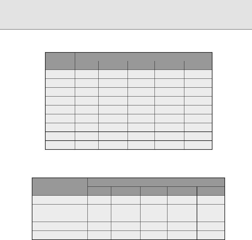
Radiation Shielding and Radiological Protection
⊡ Table
Compositions of Five Representative Soil Types
Weight Fractions for Soil Types
Nominal Dry porous Dry dense Wet porous Wet dense
Hydrogen . . . . .
Oxygen . . . . .
Silicon . . . . .
Aluminum . . . . .
Iron . . . . .
Calcium . . . . .
Potassium . . . . .
Sodium . . . . .
Magnesium . . . . .
Source: Shue et al. ()
⊡ Table
Characteristics of Five Representative Soil Types
Soil Type
Nominal Dry porous Dry dense Wet porous Wet dense
Porosity
a
. . . . .
Free water content
b
. . . . .
Bound water content
c
. . . . .
Mineral density (g/cm
)
d
. . . . .
In situ density (g/cm
) . . . . .
a
Fraction of total volume occupied by water and air.
b
Ratio of free water mass to mineral mass.
c
Ratio of bound water mass to mineral mass.
d
Mineral density includes bound water.
Source: Shue et al. ()
orpressuresaswellastoaccountforhumidity.Indryair,weightfractionsbyelementareN:
., O: ., C: ., and Ar: ..
Ar, present at . atomic fraction, captures
thermal neutrons with the cross section of . b. e product
Ar decays with a half-life of
m, releasing a beta particle and, with .% frequency, a .-MeV gamma ray.
Hydrogen present in water with . weight fraction, captures thermal neutrons with a
cross section of . b and, in the process, releases a .-MeV-capture gamma ray. In a com-
plementary reaction with .-MeV threshold, photoneutrons are produced in the interaction
of gamma rays with deuterium.
Soils oen nd use as radiation shields; however, water content is highly variable, depending
on environmental conditions.
> Tables and list characteristics of a range of soil types.
Similarly, untreated wood, though useful for neutron attenuation, loses water over time and is,
therefore, generally found unacceptable as a shield material.

Radiation Shielding and Radiological Protection
.. Concrete
Cost, density, compressive strength, ease of placement, and eectiveness in attenuation of both
neutrons and gamma rays make concrete a highly desirable shielding material. Neutron shield-
ing by concrete and the importance of water (hydrogen) content are addressed earlier in this
chapter and is not repeated here. Types of concrete are characterized by the type of aggregate,
siliceous referring to quartz based aggregate and calcareous referring to limestone based aggre-
gate.
> Table lists components of three types of “ordinary” concrete: NBS Type , Type ,
and the current NIST ordinary concrete (Hubbell & Seltzer ). Type is commonly cited
and appears to be accepted as “representative.” High-density concrete is oen used to provide
greater attenuation for a given thickness. Additives for this type of concrete include scrap metal
such as steel punchings and metallic ores. Magnetite concrete (ρ =.g/cm
)containsinthe
mix iron oxide to the extent lb/yd
.Bariteconcrete(ρ =.g/cm
)containsbariumsul-
fate ore to the extent lb/yd
. ANSI/ANS-.- lists other high-density concretes plus
alow-density(ρ =.g/cm
) serpentine concrete for high temperature applications.
Reinforcing steel, or rebar, provides tensile strength and adds density to concrete. For
gamma-ray shielding, it is generally satisfactory to conceptually homogenize the reinforced
concrete. For neutron shielding, however, channeling eects very oen call for treatment of the
reinforced concrete as a combination of a continuous concrete phase with steel heterogeneities.
⊡ Table
Compositions of Types and and NIST Ordinary
Concretes
Elemental Composition (partial g/cm
)
Element Type Type NIST
Hydrogen . . .
Carbon . .
Oxygen . . .
Sodium . .
Magnesium . . .
Calcium . . .
Aluminum . . .
Sulfur . .
Silicon . . .
Potassium . . .
Iron . . .
Nickel .
Phosphorus .
Total . . .
Source: ANL- (nd ed.), ANSI/ANS-.-, Hubbell and
Seltzer ()

Radiation Shielding and Radiological Protection
.. Metallic Shielding Materials
Very oen it is necessary to address shielding properties of alloy (carbon) steels and stainless
steels. Alloy steel has a nominal density of . g/cm
, contains . to .% carbon by weight
plus varying concentrations of Si, Mn, Cr, Ni, Mo, P, and S. Stainless steel, with density typically
. – . g / c m
, contains up to about .% carbon by weight and large concentrations of Mn,
Cr, Ni, and Mo. In the presence of neutrons, cobalt must be held to the lowest concentration
possible to prevent activation yielding the gamma-ray emitter
Co.
Other important metallic shielding materials are lead, tungsten, and uranium. Next to con-
crete, lead is no doubt the most common shield material. It has low strength, a low melting
point (
○
C ), and a high density (. g/cm
). Tungsten has high strength and a high melting
point (
○
C ). Uranium, especially uranium depleted in
U, has high strength, intermediate
melting point (
○
C),andahighdensity(.–.g/cm
).
.. Special Materials for Neutron Shielding
Shielding of epithermal or fast neutrons requires a two stage process. Fastneutrons can rarely be
captured or absorbed; thus, it is rst necessary to slow neutrons to thermal energies, as the rst
step, and then to absorb them. e slowing-down process itself may be in two stages. Neutrons
with many MeV of energy may be slowed by inelastic scattering with atoms of, for example,
iron. is is the removal process discussed in
> .. At neutron energies below about MeV,
the elastic scattering cross section of hydrogen exceeds the inelastic scattering cross section of
iron. us, in addition to a component such as iron, a hydrogenous component is needed for
ecient neutron thermalization. ermal neutrons are readily captured, unfortunately, in most
instances releasing high-energy capture-gamma rays. us, for an eective neutron shield, a
strong absorber such as boron or lithium, perhaps indium or cadmium, is needed to avoid
signicant capture-gamma rays.
Boron for Neutron Attenuation
Natural boron contains . atomic percent
Band.percent
B, the former with a -b
(-m/s) absorption cross section, the latter with only mb. e absorption of a neu-
tron by
B releases a .-MeV gamma ray – signicant, but of lower energy than most
capture gamma rays. Boron shielding materials are available in the form of boron carbide,
B
C, with density . g/cm
, borated graphite, boron carbide mixed in graphite, and boral
(a mixture of boron carbide in aluminum cladding). Plates or sheets of boral commonly
contain % boron by weight and are available up to by m
in area and thicknesses of
. and . in. Boron shielding is also available as borated polyethylene in a wide range
of shapes and compositions, in a wide range of boron concentrations, and even in castable
form. For mixed neutron and gamma-ray shielding, lead-loaded borated polyethylene is also
available.
Lithium for Neutron Attenuation
Natural lithium contains . atomic percent
Li and . percent
Li. e former
has an exceptionally high cross section ( b) for thermal-neutron absorption and

Radiation Shielding and Radiological Protection
produces no secondary gamma rays. It is light in weight and available enriched in
Li. It is
oered commercially as lithium polyethylene, with .% lithium by weight and in a variety of
shapes.
.. Materials for Diagnostic X-Ray Facilities
ere are six materials of prime concern in the design of diagnostic facilities. Of these, con-
crete, steel, and lead have already been addressed. Others are wood, plate glass, and gypsum
wallboard. Shielding design considerations are documented by Jaeger et al. (), Archer et al.
(), and NCRP ().
Depending on hydrogen content, wood density varies from . to ., nominally . g/cm
,
and is essentially cellulose, water, and lignin. Crown glass, a silica soda lime glass, is durable and
has a low index of refraction. Density is .–. g/cm
. Lead oxide may be added at up to about
. weight fraction Pb to yield lead glass with density up to about . g/cm
. Sheets are available
with lateral dimensions up to about cm and thicknesses up to about cm. Plaster board, or
gypsum wallboard, has a density typically . g/cm
. By weight fraction, gypsum composition
is H ., O ., S ., and Ca .. Typical thickness is mm of gypsum plus mm
of paper. Sheets may be lined with lead in thicknesses / in to / in.
. A Review of Software Resources
Listed below are selected soware packages of interest in shielding design and analysis. All are
available from the Radiation Safety Information Computational Center, accessible on line at
http://www-rsicc.ornl.gov/.
• QAD-CGGP: point kernel code featuring combinatorial D geometry and source options
with geometric progression buildup factors for gamma rays
• QADMOD-GP: point kernel code featuring faster D geometry and source options with
geometric-progression buildup factors for gamma rays
• G-: point kernel code featuring multi-group gamma-ray scattering with QAD geometry
and GP-buildup factors
• ISOSHLD: point kernel code featuring multiple isotope sources, limited geometry, and
source description
• DOORS: discrete ordinates code package incorporating ANISN, DORT, and TORT codes
for , , and D discrete ordinates calculations
• PA RT I S N: discrete ordinates code featuring multidimensional, time-dependent, multigroup
discrete ordinates transport code system
• COHORT: Monte Carlo code featuring radiation transport; exible geometry
• MORSE: Monte Carlo code featuring multigroup neutron and gamma-ray transport; com-
binatorial geometry
• MCNP: Monte Carlo code featuring continuous energy, neutral particle transport; exible
geometry
• ORIGEN: neutron activation code featuring neutron activation, radioactive decay, and
source-term analysis

Radiation Shielding and Radiological Protection
. Shielding Standards
Listed below are ANSI/ANS standards pertinent to shielding design. Standards . and .. cite
standards of other sponsors such as ASME and IEEE as well as selected international standards.
• ANSI/ANS-.-: Decay Heat Power in Light Water Reactors
• ANSI/ANS-..-: Neutron and Gamma-Ray Cross Sections for Nuclear Radiation
Protection Calculations for Nuclear Power Plants
• ANSI/ANS-..-;R;R (R=Rearmed): Program for Testing Radiation Shields
in Light Water Reactors (LWR)
• ANSI/ANS-.-: Nuclear Analysis and Design of Concrete Radiation Shielding for
Nuclear Power Plants
• ANSI/ANS-..-: Specication for Radiation Shielding Materials
• ANSI/ANS-..-;R;R (R=Rearmed): Calculation and Measurement of
Direct and Scattered Gamma Radiation from LWR Nuclear Power Plants
• ANSI/ANS-.-: Radioactive Source Term for Normal Operation for Light Water
Reactors
• ANSI/ANS-.-: Nuclear Data Sets for Reactor Design Calculations
• ANSI/ANS-..-: e Determination of ermal Energy Deposition Rates in Nuclear
Reactors
Health Physics
As it passes through biological tissue, radiation interacts with ambient atoms and produces
chemical free radicals that, in turn, cause oxidation–reduction reactions with cell biomolecules.
However, how such reactions aect the cell and produce subsequent detrimental eects to an
organism is not easily determined. Because of the obvious concern about the biological eects of
radiation, much research has been directed toward understanding the hazards associated with
ionizing radiation.
ere are two broad categories of radiation hazards to humans. Hereditary eects result in
damage to the genetic material in germ cells that, although not detrimental to the individual
exposed, may result in hereditary illness to succeeding generations. Somatic eects aect the
individual exposed and are further classied by the nature of the exposure, for example, acute
or chronic, and by the time scale of the hazard, for example, short term or long term. e short-
term acute eects on the gastrointestinal, respiratory, and hematological systems are referred to
as the acute radiation syndrome.
e eects of human exposure to ionizing radiation depend on both the exposure as well
as its duration. Acute, life-threatening exposures lead to deterministic consequences requiring
medical treatment. For such exposures, illness is certain, with the type and severity depending
on the exposure and the physical condition of the individual exposed.
By contrast, minor acute or chronic low-level exposures produce stochastic damage to cells
and subsequent ill eects are quantiable only in a probabilistic sense; hereditary illness or
cancer may or may not occur. Only the probability of illness, not its severity, is dependent on
the radiation exposure. Such consequences are, thus, stochastic as distinct from deterministic.
Although the eects of low-level radiation exposures to a large number of individuals can be
estimated, the eect to a single individual can be described only probabilistically.

Radiation Shielding and Radiological Protection
. Deterministic Effects from Large Acute Doses
ere are two circumstances under which a person can receive high doses of ionizing radiation.
e rst is accidental, and most likely involves a single exposure of short duration. e second is
from medical treatments, and oen involves doses delivered daily for several weeks and which
may be delivered under conditions designed to intensify the response of certain organs and tis-
sues to the exposures. Here, only single acute exposures to all or part of the body are considered.
Issues such as fractionation and eect modication, which pertain largely to medical exposures,
are not addressed.
.. Effects on Individual Cells
e probability that a particular radiation exposure kills a cell or prevents it from divid-
ing depends on many factors. e two most important factors are the dose rate and the
LET of the radiation. Doses delivered at low dose rates allow the cell’s natural repair mech-
anism to repair some of the damage, so that the consequences are generally not as severe
as if the doses were delivered at high dose rates. High LET radiation, like alpha particles,
creates more ion–electron pairs closer together than does low LET radiation. Consequently,
high LET radiation produces more damage to a cell it passes through than would, say, a
photon.
epositioninacell’slifecycleatthetimeofexposurealsogreatlyaectsthedamage
to the cell. Cell death is more likely if the cell is in the process of division than if it is in
a quiescent state. us, radiation exposure results in more cell death in organs and tissues
with rapidly dividing cells, such as the fetus (especially in the early stages of gestation), the
bone marrow, and the intestinal lining. Whole-body absorbed doses of several Gy are life-
threatening largely because of stem cell killing in the bone marrow and lining of the intestines.
However, in these tissues and in most other tissues and organs of the body, there are ample
reserves of cells, and absorbed doses of much less than one Gy are tolerable without signi-
cant short-term eect. Similarly, radiation doses which would be fatal if delivered in minutes
or hours may be tolerable if delivered over signicantly longer periods of time. Age, gen-
eral health, and nutritional status are also factors in the course of events following radiation
exposure.
For those tissues of the body for which cell division is slow, absorbed doses which might be
fatal if delivered to the whole body may be sustained with little or no eect. On the other hand,
much higher absorbed doses may lead ultimately to such a high proportion of cell death that,
because replacement is so slow, structural or functional impairment appears perhaps long aer
exposure and persists perhaps indenitely.
.. Deterministic Effects in Organs and Tissues
In this section, only deterministic somatic eects – eects in the person exposed – are con-
sidered. ese eects have well-dened patterns of expression and thresholds of dose, below
which the eects do not occur. e severity of the eect is a function of dose. e stochastic
carcinogenic and genetic eects of radiation are addressed later.

Radiation Shielding and Radiological Protection
e risk, or probability of suering a particular eect or degree of harm, as a
function of radiation dose above a threshold dose D
th
, can be expressed in terms of
ath-percentile dose D
, or median eective dose, which would lead to a specied eect
or degree of harm in half the persons receiving that dose. e D
dose depends, in general,
on the rate at which the dose is received. For doses below a threshold dose D
th
, the eect
does not occur.
A summary of important deterministic eects is given in
> Table . Information about
these and other eects on particular organs and tissues can be found in the following sources:
Information is taken from the following sources: (Langham ; Upton and Kimball ; Wald
; NCRP a; Vogel and Motulsky ; Pochin ; ICRP , ; UN ; Shultis and
Faw ).
.. Potentially Lethal Exposure to Low-LET Radiation
e question of what constitutes a lethal dose of radiation has, of course, received a great deal of
study. ere is no simple answer. Certainly, the age and general health of the exposed person are
key factors in the determination. So, too, are the availability and administration of specialized
medical treatment. Inadequacies of dosimetry make interpretation of sparse human data di-
cult. Data from animal studies, when applied to human exposure, are subject to uncertainties in
extrapolation. Delay times in the response to radiation, and the statistical variability in response
have led to expression of the lethal dose in the form, for example, LD
/
,meaningthedose
is fatal to % of those exposed within days. e dose itself requires a careful interpreta-
tion. One way of dening the dose is the free-eld exposure, in roentgen units, for gamma or
⊡ Table
Median effective absorbed doses D
and threshold doses D
th
for expo-
sure of different organs and tissues in the human adult to gamma
photons at dose rates ≤. Gy h
−
Organ/Tissue Endpoint D
(Gy) D
th
(Gy)
Skin Erythema ± ±
Moist desquamation ± ±
Ovary Permanent ovulation supression ± . ± .
Testes Sperm count supressed for y . ± . . ± .
Eye lens Cataract . ± . . ± .
Lung Death
a
± ±
GI system Vomiting ± . .
Diarrhea ± .
Death ±
Bone marrow Death . ± . . ± .
a
Dose rate . Gy/h
Source: Scott and Hahn ()

Radiation Shielding and Radiological Protection
X-rays. A second is the average absorbed dose to the whole body. A third is the mid-line
absorbed dose, that is, the average absorbed dose near the abdomen of the body. For gamma
rays and X-rays, the mid-line dose, in units of rads, is about two-thirds the free-eld expo-
sure, in units of roentgens. e evaluation by Anno et al. () for the lethal doses of ionizing
radiationaregivenin
> Table . e eects of large doses below the threshold for lethal-
ity are summarized in NCRP Report () and by Anno et al. (). For extremely
high doses (> Gy), death is nearly instantaneous, resulting from enzyme inactivation or
possibly from immediate eects on the electrical response of the heart (Kathren ). Lesser,
but still fatal doses, lead promptly to symptoms known collectively as the prodromal syndrome.
e symptoms, which are expressed within a -h period are primarily gastrointestinal (e.g.,
nausea, diarrhea, cramps, and dehydration) and neuromuscular (e.g., fatigue, sweating, fever,
headache, and hypotension). For high doses with potential survival, the prodromal stage is
followed by a latent stage, a stage of manifest illness, and a recovery stage beyond – weeks
post-exposure.
. Hereditary Illness
In , Hermann Muller discovered that fruit ies receiving high doses of radiation could pro-
duce ospring with genetic abnormalities. Subsequent animal and plant studies have demon-
strated a nearly linear relationship between dose and mutation frequency, for doses as low as
mSv. However, there is almost no evidence of radiation-induced mutations in humans.
Indeed, the only unequivocal evidence relates to chromosomal rearrangement in sperma-
tocytes. Nevertheless, animal studies clearly indicate that radiation can produce heritable
mutational eects in the humans. Because radiation-induced mutation rates in humans are
unknown, even for atom bomb survivors, estimation of risks to human populations are based
largely on extrapolation of studies of radiation eects in other mammals, notably the mouse.
e estimation of human hereditary risks from animal studies involve many assumptions,
and the estimates turn out to be a very small fraction of the natural incidence of such ill-
ness, thereby, explaining why radiation-induced hereditary illness has not been observed in
humans.
⊡ Table
Lethal doses of radiation
Mid-line absorbed
Lethality dose (Gy)
LD
/
.–.
LD
/
.–.
LD
/
.–.
LD
/
.–.
LD
/
.–.

Radiation Shielding and Radiological Protection
.. Classification of Genetic Effects
> Table reports estimates of the natural incidence of human hereditary or partially hered-
itary traits causing serious handicap at some time during life. Inheritance of a deleterious trait
results from mutation(s) in one or both maternal and paternal lines of germ cells. Here a muta-
tion is either a microscopically visible chromosome abnormality or a submicroscopic disruption
in the DNA making up the individual genes within the chromosomes. Mutations take place in
both germ cells and somatic cells, but only mutations in germ cells are of concern here.
Regularly inherited traits are those whose inheritance follows Mendelian laws. ese are
autosomal dominant, X-linked, and recessive traits. Examples of autosomal dominant disor-
ders, that is, those which are expressed even when the person is heterozygous for that trait, are
certain types of muscular dystrophy, retinoblastoma, Huntington’s chorea, and various skele-
tal malformations. Examples of recessive disorders, that is, those which are expressed only
when the individual is homozygous for the trait, include Tay–Sachs disease, phenylketonuria,
sickle-cell anemia, and cystic brosis. X-linked disorders, that is, those traits identied with
genes in the X chromosome of the X–Y pair and which are expressed mostly in males, include
hemophilia, color blindness, and one type of muscular dystrophy. In the X–Y chromosome
pair, otherwise recessive genetic traits carried by the “stronger” maternal X chromosome are
expressed as though the traits were dominant. Chromosome abnormalities are of two types:
⊡ Table
Genetic risks from continuing exposure to low-LET, low-dose, or
chronic radiation as estimated by the BEIR and UNSCEAR committees
on the basis of a doubling-dose of Gy
Per million progeny
Type of Disorder
Natural
frequency
Cases/Gy
in first
generation
Cases/Gy
in second
generation
a
Mendelian autosomal
Dominant and X-linked , – –
Recessive ,
Chromosomal ,
b b
Irregularly inherited traits
Chronic multifactorial , – –
Congenital abnormalities , –
Total , – –
Total risk (% of baseline) .–. .–.
a
Risk to the second generation includes that to the first except for congentital
abnormalities for which it is assumed that between % and % of the abnormal
progeny in the first generation may transmit the damage to the second post-
radiation generation, the remainder causing lethality.
b
Assumed to be included with Mendelian diseases and congenital abnormalities.
Source: UN (); adopted by NAS () and ICRP ()

Radiation Shielding and Radiological Protection
those involving changes in the numbers of chromosomes and those involving the structure
of the chromosomes themselves. Down syndrome is an example of the former. With natu-
ral occurrence, numerical abnormalities are more common. By contrast, radiation-induced
abnormalities are more frequently structural abnormalities.
ere is a very broad category comprising what are variously called irregularly inherited
traits, multifactorial diseases, or traits of complex etiology. is category includes abnormali-
ties and diseases to which genetic mutations doubtlessly contribute, but which have inheritances
much more complex than result from chromosome abnormalities or mutations of single genes.
ey are exemplied by inherited predispositions for a wide variety of ailments and conditions.
One or more other multifactorial disorders, including cancer, are thought to aict nearly all per-
sons sometime during life; however, the mutational components of these disorders are unknown
even as to orders of magnitude (NAS ). Also included in
> Table is a subgroup of irreg-
ularly inherited traits identied as congenital abnormalities. ese are well-identied conditions
such as spina bida and cle palate, with reasonably well-known degrees of heritability.
.. Estimates of Hereditary Illness Risks
> Table also summarizes the UNSCEAR genetic risk estimates. e results are for low
LET radiation (quality factor Q =);thus,theabsorbeddoseanddoseequivalentarethesame.
ese estimates are based on a population-averaged gonad-absorbed dose of Gy ( rad) to
the reproductive population which produce one-million live-born. Because of the linearity of
the dose-eect models used, these estimated hereditary risks are the same whether the gonad
dose is received in a single occurrence or over the -year reproduction interval. e popula-
tion for these results is assumed static in number, so that one million born into one generation
replace one million in the parental generation.
Data in
> Table give the expected number of genetic illness cases appearing in the rst
and second generations, each receiving radiation exposure. Except as indicated,cases in the sec-
ond generation include the new cases from exposure of the rst generation plus cases resulting
from exposure of the previous generation, for example, – cases of autosomal dominant
and X-linked class and no cases of the autosomal recessive class. e ICRP () suggests over-
all risk coecients for heritable disease up to the second generation as . Sv
−
for the whole
population and . Sv
−
for adult workers.
. Cancer Risks from Radiation Exposures
A large body of evidence leaves no doubt that ionizing radiation, when delivered in high doses,
is one of the many causes of cancer in the human. Excess cancer risk cannot be observed at doses
less than about . Gy and, therefore, risks for lower doses cannot be determined directly (UN
). At high doses, in almost all body tissues and organs, radiation can produce cancers that
are indistinguishable from those occurring naturally. Consequently, radiation-induced cancer
can be inferred only from a statistical excess above natural occurrence. > Table summa-
rizes natural incidence and mortality for the male and female. ICRP Report () provides
comprehensive age and gender dependentincidence and mortality data for Euro-American and
Asian populations.

Radiation Shielding and Radiological Protection
⊡ Table
Annual cancer incidence and death rates per , population in the United
States population
Incidence per
per year Deaths per
per year
Primary site Males Females Males Females
Leukemia . . . .
Lymphoma . . . .
Respiratory . . . .
Digestive . . . .
Breast . .
Genital . . . .
Urinary . . . .
Other . . . .
Total . . . .
Source: HHS ()
ere is a large variation in the sensitivity of tissues and organs to cancer induction by radi-
ation. For whole-body exposure to radiation, solid tumors are of greater numerical signicance
than leukemia. e excess risk of leukemia appears within a few years aer radiation exposure
and largely disappears within years aer exposure. By contrast, solid cancers, which occur
primarily in the female breast, the thyroid, the lung, and some digestive organs, characteristi-
cally have long latent periods, seldom appearing before years aer radiation exposure and
continuing to appear for years or more. It is also apparent that age at exposure is a major fac-
tor in the risk of radiation-induced cancer. Various host or environmental factors inuence the
incidence of radiation-induced cancer. ese may include hormonal inuences, immunological
status, and exposure to various oncogenic agents.
.. Estimating Radiogenic Cancer Risks
Our knowledge about radiation-induced cancer is based on epidemiological studies of people
who have received large radiation doses. ese populations include atomic bomb survivors,
radiation therapy patients, and people who have received large occupational doses. Some
, survivors of the atomic weapon attacks on Hiroshima and Nagasaki and their ospring
remain under continuing study, and much of our knowledge about radiation-induced cancer
derives from this group. Occupational groups include medical and industrial radiologists and
technicians, women who ingested large amounts of radium while painting instrument dials
during World War I, and miners exposed to high concentrations of radon and its daughter
radionuclides. Finally, radiation therapy patients have provided much information on radia-
tion carcinogenesis. ese include many treated with X-rays between and for severe
spinal arthritis, Europeans given
Ra injections, and many women given radiation therapy for
cervical cancer.

Radiation Shielding and Radiological Protection
. TheDoseandDose-RateEffectivenessFactor
Assessment of cancer risks from radiation exposure is concerned primarily with exposures of
population groups to low doses at low dose rates. As just indicated, however, there is little
choice but to base risk estimates on consequences of exposures at high doses and dose rates.
Furthermore, organizations such as the ICRP and the NCRP have endorsed, and government
organizations have agreed, to base risk estimates on a linear no-threshold relationship between
cancer risk and radiation dose. An exception applies to radiation-induced leukemia, for which
a quadratic, no-threshold relationship has been adopted. How does one reconcile low-dose risk
estimates based on high-dose data? e answer is addressed in
> Fig. . Symbols display a
limited base of data for high doses and dose rates. A central curved line displays what may be
thetruedoseresponse(sayalinearquadraticrelationship).eupperstraightline,withslope
α
H
is the linear, no-threshold approximation for the high-dose data. e lower straight line,
with slope α
L
is tangent to the true response curve in the limit of low dose and low-dose rate,
conditions allowing for partial repair of radiation damage. Risks at low doses and dose rates, if
computed on the basis of α
H
, need to be corrected by division by the ratio α
H
α
L
dened as the
DDREF,thedose and dose rate correction factor.
.. Dose–Response Models for Cancer
Evidence is clear that absorbed doses of ionizing radiation at levels of Gy or greater may lead
stochastically to abnormally high cancer incidence in exposed populations. However, there is
no direct evidence that chronic exposure to low levels of ionizing radiation may likewise lead
to abnormally high cancer incidence. Risk estimates for chronic, low-level exposure requires
extrapolation of high-dose and high-dose-rate response data to low doses. Methods used for
extrapolation are oen controversial, any one method being criticized by some as overpredictive
and by others as underpredictive.
Linear approximation
at high dose, with
slope a
H
Linear approximation
at low dose, with slope a
L
High-dose
measurements
True
response
Radiation dose D (Gy)
Excess relative risk of cancer
0123
4
0
0.1
0.2
0.3
0.4
0.5
⊡ Figure
Basisforthedoseanddose-rateeffectivenessfactor

Radiation Shielding and Radiological Protection
Current risk estimates for cancer have as the basic elements dose responses that are func-
tions of the cancer site or type, the age a
o
(y) at exposure, the age a (y) at which the cancer
is expressed or the age at death, and the sex s of the subject. e radiogenic cancer risk is ex-
pressed as
risk =R
o
(s, a)×EER(D, s, a
o
, a).()
Here, R
o
is the natural cancer risk as a function of sex, site, and age at cancer expression, for
both incidence and mortality; and EER is the excess relative risk function that is determined by
tting a model to observed radiogenic cancer incidence or mortality for cancer at a particular
site. For example, the excess relative risk for all solid cancer, except thyroid and nonmelanoma
skin cancer, is expressed as (NAS )
ERR(D, s, a
o
, a)=β
s
D exp[e
∗
γ](a)
η
,()
in which D is the dose in Sv. In this particular model, the empirical parameter e
∗
=(a
o
−)
for a
o
< and zero for a
o
≥. Parameters β
s
, γ,andη depend on whether the estimate is for
incidence or mortality. For example, for cancer incidence, γ =−., η =−., and β
s
=.
for males and . for females.
To use (), t h e natural risk R
o
(s, a) for the type of cancer of concern must be
known. Data for natural risk are available, but are too extensive to be presented here. ey
may be found in publications of the Centers for Disease Control (HHS ) and on-line
at http://www.cdc.gov/cancer/ncpr/uscs or http://seer.cancer.gov/statistics. For example, US
death rates per , US males, for all races and all cancer sites combined increase from
. for infants to . at age –, and at age –. For females, the corresponding rates
are ., ., and , respectively.
It should be emphasized that, in examining these risks of cancer from radiation exposure,
one should keep in mind the overall or natural risk of cancer. As indicated in
> Table ,two
persons per thousand in the United States die each year from cancer. As will be seen in the next
section, the overall lifetime risk of cancer mortality is about one in ve for males and about one
in six for females.
.. Average Cancer Risks for Exposed Populations
e BEIR-VII Committee of the National Academy of Sciences (NAS ) made various esti-
mates of the risk of excess cancer incidence and mortality resulting from low-LET (gamma-ray)
exposures. ese risks are summarized in
> Table by sex and by age at exposure. Although
the data are for conditions of low dose and dose rate, they were generated in large part from
cancer incidence and mortality experienced by survivors of atomic weapons at Hiroshima and
Nagasaki. At lower doses and dose rates, risks are somewhat less because biological repair mech-
anisms can repair a greater fraction of the genetic damage produced by the radiation. is
eect is accounted for in risk estimates for leukemia, which are based on a linear-quadratic
dose–response model. For solid cancers, risks have been modied by application of a dose and
dose-rate eectiveness factor, namely, by dividing high-dose and dose-rate data by the DDREF
value of .. e ICRP (, ) continues to recommend a DDREF value of ..
e BEIR-VII Committee also calculated risks to the US population under three low-LET
exposure scenarios: () single exposure to . Gy, () continuous lifetime exposure to mGy

Radiation Shielding and Radiological Protection
⊡ Table
Excess lifetime cancer incidence and mortality for the US population by
age at exposure for a whole-body dose of . Gy ( rad) from low LET
radiation to populations of
males or females
Age at exposure (years)
Females
Incidence
Leukemia
All solid
Mortality
Leukemia
All solid
Males
Incidence
Leukemia
All solid
Mortality
Leukemia
All solid
Source: based on (NAS )
per year, and () exposure to mGy per year from age to age . Results are summarized in
> Table . e rst scenario is representative of accidental exposure of a large population (the
US population), the second of chronic exposure, and the third of occupational exposure.
For example, for leukemia mortality, with % condence limits (not given in
> Table ), for
a single exposure of the US population to . Gy, the risk per , is (–) for the male
and (–) for the female. For nonleukemia mortality per , fatalities are (–
) for the male and (–) for the female. For this case, the total low-dose cancer
mortality risk for the US population is . ×( +)(. Gy ×
)=. per Gy, which
can be rounded to . per Gy, or ×
−
per rem. is risk should be used as an overall cancer
risk factor for environmental exposures, that is, small exposures obtained at low dose rates. e
ICRP () nominal risk recommendations are . Sv
−
for the whole population and .
Sv
−
for adult workers.
. Radiation Protection Standards
It was recognized near the beginning of the twentieth century that standards were needed to
protect workers and patients from the harmful consequences of radiation. Many sets of stan-
dards, based on dierent philosophies, have been proposed by several national and international

Radiation Shielding and Radiological Protection
⊡ Table
Excess cancer incidence and mortality per , males and ,
females in the stationary US population for three low-dose exposure
scenarios
Cases per
Deaths per
Cancer Type Males Females Males Females
Single Exposure to . Gy ( rad):
Radiation Induced:
leukemia
nonleukemia
total
Natural Expectation:
leukemia
nonleukemia
total
Continuous Lifetime Exposure
to mGy ( mrad) per year:
Radiation Induced:
leukemia
nonleukemia
total
Continuous Exposure to mGy
( rad) per year from age to :
Radiation Induced:
leukemia
nonleukemia
total
Source: based on (NAS )
standards groups. e earliest standards were based on the concept of tolerable doses below
which no ill eects would occur. is was replaced in by the National Council on Radiation
Protection and Measurements (NCRP) in the United States which introduced standards based
on the idea of permissible doses, that is, a dose of ionizing radiation which was not expected to
cause appreciable body injury to any person during his or her lifetime.
.. Risk-Related Dose Limits
Today it is understood that low-level radiation exposure leads to stochastic hazards and that
modern radiation standards should be based on probabilistic assessments of radiation hazards.

Radiation Shielding and Radiological Protection
is new line of thinking is exemplied by a report to the ICRP by the Task Group on Dose
Limits. Key portions of the report are summarized as follows. It must be noted that the report is
unpublished and not necessarily reective of the ocial ICRP position. e tentative dose limits
examined in the report were not based on explicit balancing of risks and benets, then thought
to be an unattainable ideal. Rather, they were based on the practical alternative of identifying
acceptable limits of occupational radiation risk in comparison with risks in other occupations
generally identied as having a high standard of safety and also having risks of environmental
hazards generally accepted by the public in everyday life.
Linear, no-threshold dose-response relationships were assumed for carcinogenic and
genetic eects, namely, a ×
−
probability per rem whole-body dose equivalent for malignant
illness or a ×
−
probability per rem for hereditary illness within the rst two generations of
descendants (ICRP ). For other radiation eects, absolute thresholds were assumed.
To illustrate the reasoning for risk-based limits, consider the occupational whole-body
dose-equivalent limit of rem/y. For occupational risks, it was observed that “occupations with
a high standard of safety” are those in which the average annual death rate due to occupational
hazardsisnomorethanpermillionworkers.Anacceptable risk was taken as per million
workers per year, or a -year occupational lifetime risk of fatalities per workers, that is,
.. It was also observed that in most facilities in which radiation may expose workers, the
average annual doses are about percent of the doses of the most highly exposed individuals,
with the distribution highly skewed toward the lower doses. To ensure an average lifetime risk
limit of ., an upper limit of times this value was placed on the lifetime risk for any one
individual. e annual whole-body dose-equivalent limit for stochastic eects was thus taken
as ( ×.)( y ×. malignancies/Sv)=. Sv ( rem) per year. Similar reasoning is
used to set public dose limits and limits for nonstochastic eects (Shultis and Faw ).
.. The NCRP Exposure Limits
e concept of “risk-based” or “comparable-risk” dose limits provides the rationale for the
ICRP and the NCRP recommendations for radiation protection, and which serve as the
present basis for the US radiation protection standards. A summary of these dose limits is given
in
> Table .
Acknowledgments
e authors of this chapter gratefully acknowledge the guidance and support of their colleagues
and mentors in the eld of radiation shielding and radiation protection. e late Arthur Chilton,
our colleague and friend, will be known to readers of this chapter for his breadth of inter-
est and experience in radiation shielding. He was the coauthor of and the inspiration for our
rst book on radiation shielding. Of the many who taught us, we particularly acknowledge
Lewis Spencer, Martin Berger, Herbert Goldstein, and Norman Schaeer. We acknowledge the
American Nuclear Society too for their continuing publication of our textbooks on radiation
shielding and radiological assessment, from which much of the material in this chapter has been
taken.

Radiation Shielding and Radiological Protection
⊡ Table
The NCRP recommendations for exposure limits
Type of Dose mSv rem
Occupational exposures (annual):
. Limit for stochastic effects
. Limit for nonstochastic effects:
a. Lens of the eye
b. All other organs
. Guidance: cumulative exposure age (y) ×
Public exposures (annual):
. Continuous or frequency exposure .
. Infrequent exposure .
. Remedial action levels .
. Lens of the eys, skin and extremities
Embryo–fetus exposure:
. Effective-dose equivalent .
. Dose-equivalent limit in a month . .
Negligible individual risk level (annual):
. Effective-dose equivalent per source or practice . .
Source: NCRP ()
References
Albert RD, Welton TA () A simplified
theory of neutron attenuation and its appli-
cation to reactor shield design. USAEC
Report WAPD- (Del.), Westinghouse Elec-
tric Corporation, Atomic Power Division,
Pittsburgh, PA
Alsmiller RG Jr, Mynatt RR, Barish J, Engle WW Jr
() Shielding against neutrons in the energy
range to MeV. Nucl Instrum Methods
:
Anno GH, Baum SJ, Withers HR, Young RW ()
Symptomatology of acute radiation effects in
humans after exposure to doses of .– Gy.
Health Phys :–
ANSI/ANS-..-, American National Standard
() Neutron and gamma-ray flux-to-dose-
rate factors. American Nuclear Society, La
Grange Park, IL
ANSI/ANS-..-, American National Standard
() Calculation and measurement of direct
and scattered gamma radiation from LWR
nuclear power plants. American Nuclear Society,
La Grange Park, IL
ANSI/ANS-..-, American National Standard
() Gamma ray attenuation coefficients
and buildup factors for engineering materials.
American Nuclear Society, La Grange Park,
IL (Available as Data Library Collection DLC-
/ANS- from the Radiation Shielding
Information Center, Oak Ridge National
Laboratory, Oak Ridge, TN)
ANSI/ANS-.-, American National Standard
() Decay heat power in light water reactors.
American Nuclear Society, La Grange Park, IL
ANSI/ANS-.-, American National Standard
() Nuclear analysis and design of concrete

Radiation Shielding and Radiological Protection
radiation shielding for nuclear power plants.
American Nuclear Society, La Grange
Park, IL
ANSI/ANS-..- () Specification for radi-
ation shielding materials. American Nuclear
Society, La Grange Park, IL
Archer BR, Fewell TR, Conway BJ, Quinn PW
() Attenuation properties of diagnostic X-
ray shielding materials. Med Phys :–
Archer BR, Thornby JI, Bushong SC () Diagnos-
tic X-ray shielding design based on an empir-
ical model of photon attenuation. Health Phys
:–
Artigas R, Hungerford HE () A numerical treat-
ment of the attenuation of neutrons by air ducts
in shields. Nucl Sci Eng :
Avery AF, Bendall DE, Butler J, Spinney KT ()
Methods of calculation for use in the design of
shields for power reactors. Report AERE-R ,
Atomic Energy Research Establishment, Oxford-
shire, England
Baran A, Grun M () ALBEDO/ALBEZ: PC-
programs for the calculation of the attenuation
of radiation in single and double bends. NUKEM
Gmbh informal document (RSIC Code Collec-
tion CCC-), Alzenau, Germany
Bendall DE () RASH D–A mercury pro-
gramme for neutron shielding calculations.
Report AEEW-M , Atomic Energy Weapons
Establishment, Winfrith, Dorse, England
Blizard EP () Shield optimization with respect
to weight. In: Blizard EP (ed) Reactor handbook,
Part B: shielding, nd edn, vol III. Interscience,
New York
BlizardEP,AbbottLS(eds)()Reactorhandbook,
Part B: shielding, nd edn, vol III. Interscience,
New York
Blizard EP, Foderaro A, Goussey NG, Kovaiev EE
() Extended radiation sources (point ker-
nel integrations). In: Jaeger RG (ed) Engineer-
ing compendium on radiation shielding, chap ,
vol I. Springer, New York
Brockhoff RC, Shultis JK () A new approxi-
mation for the neutron Albedo. Nucl Sci Eng
:–
Brockhoff RC, Shultis JK, Faw RE () Skyshine
line-beam response functions for - to -MeV
photons. Nucl Sci Eng :–
Broder DL, Kayurin Yu P, KutrezovAA () An iter-
ative method for calculating gamma-ray buildup
factors in multi-layer shields. Sov J At Energy
:–
Broder DL, Tsypin SG () Attenuation in non-
hydrogenous media. In: Jaeger RG (ed) Engi-
neering compendium on radiation shielding,
vol I. Springer, New York, p
Brynjolfsson A () Water. In: Jaeger RG (ed)
Engineering compendium on radiation shield-
ing, vol II. Springer, New York, p
Bünemann D, Richter G () Multilayered shields.
In: Jaeger RG (ed) Engineering compendium on
radiation shielding, vol I. Springer, New York,
p
Burrus WR (a) Random voids and lumps. In:
Jaeger RG (ed) Engineering compendium on
radiation shielding, vol I. Springer, New York,
p
Burrus WR (b) Regular geometric void shapes.
In: Jaeger RG (ed) Engineering compendium on
radiation shielding, vol I. Springer, New York,
p
Casper AW () Modified fast neutron attenuation
functions. USAEC Report XDC--, General
Electric Corporation, Atomic Products Division,
Cincinnati, OH
Chapman GT, Storrs CL () Effective neutron
removal cross sections for shielding. USAEC
Report ORNL- (AECD-), Oak Ridge
National Laboratory, Oak Ridge, TN
Chapman JM () Computer calculation of dose
rates in two-legged ducts using the Albedo
concept. USAEC file number NP- (TR-
), Naval Civil Engineering Laboratory, Port
Hueneme, CA
Chen MF, Faw RE () Build-up factors for gamma
rays obliquely incident on slab shields of con-
crete, iron and lead. Radiat Protect Dosimetry
:–
Chilton AB () A modified formula for differen-
tial exposure Albedo for gamma rays reflected
from concrete. Nucl Sci Eng :–
Chilton AB () Effect of material composition on
neutron penetration of concrete slabs. Report
, National Bureau of Standards, Washing-
ton, DC
Chilton AB () Optimized Taylor parameters
for concrete buildup factor data. Nucl Sci Eng
:–
Chilton AB () Tschebycheff-fitted Berger coef-
ficients for Eisenhauer-Simmons gamma-ray
buildup factors in ordinary concrete. Nucl Sci
Eng :–
Chilton AB, Davisson CM, Beach LA () Param-
eters for C-H Albedo formula for Gamma rays
reflected from water, concrete, iron, and lead.
Trans Amer Nucl So c :
Chilton AB, Eisenhauer CM, Simmons GL ()
Photon point source buildup factors for air,
water, and iron. Nucl Sci Eng :–
Chilton AB, Huddleston CM () A semi-empirical
formula for differential dose Albedo for gamma
rays on concrete. Nucl Sci Eng :

Radiation Shielding and Radiological Protection
Chilton AB, Shultis JK, Faw RE () Principles
of radiation shielding. Prentice Hall, Englewood
Cliffs, NJ
Claiborne HC, Schaeffer NM () Shield design. In:
Schaeffer NM (ed) Reactor shielding for nuclear
engineers, USAEC, TID-. (Available from
NTIS, U.S. Department of Commerce, Spring-
field, VA)
Courtney JC (ed) () A handbook of radiation
shielding data. A Publication of the Shield-
ing and Dosimetry Division of the American
Nuclear Society, La Grange Park, IL
Cristy M, Eckerman KF () Specific absorbed
fractions of energy at various ages from internal
photon sources. Report ORNL/TM- ( vols),
Oak Ridge National Laboratory, Oak Ridge, TN
Dillman LT () EDISTR – A computer program
to obtain a nuclear data base for nuclear dosime-
try. Report ORNL/TM-, Oak Ridge National
Laboratory, Oak Ridge, TN
Dunn WL, Yacout AM, O’Foghluda F, Riel G
() Gamma-Ray and neutron dose-equivalent
buildup factors for infinite slabs. Nucl Sci Eng
:–
Dunn WW () Transmission of fast neutrons
through aluminum, iron and lead. Dissertation,
Air Force Institute of Technology (Armed Ser-
vices Technical Information Agency )
Eckerman KF, Westfall RJ, Ryman JC, Cristy M
() Availability of nuclear decay data in
electronic form, including beta spectra not
previously published. Health Phys :–.
(Available as DLC-, NUCDECAY Data
Library, Radiation Shielding Information
Center, Oak Ridge National Laboratory, Oak
Ridge, TN)
Eisenhauer CM, Simmons GL () Point isotropic
buildup factors in concrete. Nucl Sci Eng :–
EPA () A citizen’s guide to radon. Report OPA-
- of the U.S. Environmental Protection
Agency and the Centers for Disease Control of
the U.S. Department of Health and Human Ser-
vices, U.S. Government Printing Office
Evans RD () The atomic nucleus. McGraw-Hill,
New York
Fano U, Spencer LV, Berger MJ () Penetration
and diffusion of X rays. In: Flügge S (ed) Hand-
buch der physik, vol /. Springer, Berlin
Faw RE, Shultis JK (a) Absorbed dose buildup
factors in air for - to -MeV photons. Nucl
Sci Eng :–
Faw RE, Shultis JK (b) Radiological assessment.
Prentice Hall, Englewood Cliffs, NJ
Fewell TR, Shuping RE () Handbook of mammo-
graphic X-ray spectra. HEW Publication (FDA)
-, U.S. Department of Health, Education,
and Welfare, Rockville, MD
FewellTR,ShupingRE,HawkinsKRJr()
Handbook of computed tomography X-ray
spectra. HHS Publication (FDA) -, U.S.
Department of Health and Human Services,
Rockville, MD
Firestone RB et al () Table of isotopes, th edn,
thebookandCD-ROM.Wiley,NewYork
Foderaro A, Hall RJ () Application of three-
exponential representation of photon buildup
factors to water. Nucl Sci Eng . (Data
are also tabulated in Chilton, Shultis, and
Faw ())
Fournie EM, Chilton AB () Gamma-ray
buildup factors for concrete slab shields under
slant incidence conditions. Nucl Sci Eng :
–
Fröhner FH () Evaluation of
Cf prompt fission
neutron data from to MeV by Watt spectrum
fit. Nucl Sci Eng :–
Geiger KW, Van der Zwan L () Radioactive neu-
tron source spectra from
B(α,n) cross section
data. Nucl Instrum Methods :
George DC et al () Delayed photon sources
for shielding applications. Trans Am Nucl Soc
:
Glasstone S, Sesonske A () Nuclear reactor engi-
neering. Van Nostrand, Princeton, NJ
Goldstein H () Fundamental aspects of reac-
tor shielding. Addison-Wesley, Reading, MA
(Reprinted by Johnson Reprint Corporation,
New York, )
Goldstein H, Aronson R () Effective removal
cross sections – theory. React Sci Technol :
(USAEC Report TID-)
Goldstein H, Wilkins JE Jr () Calculations of the
penetrations of gamma rays, NDA/AEC Report
NYO-, U.S. Government Printing Office,
Wash in gt on, D C
Gopinath DV, Subbaiah KV, Trubey DK ()
Gamma-ray transport in a shield-tissue compos-
ite system and the buildup factor implications.
Nucl Sci Eng :–
GPO () Radiological health handbook. U.S. Gov-
ernment Printing Office, Washington, DC
Gronroos H () Energy dependent removal cross-
sections in fast neutron shielding theory. In:
Jaeger RG (ed) Engineering compendium on
radiation shielding, vol I. Springer, New York,
p
Grotenhuis M () Lecture notes on reactor shield-
ing. Report ANL-, Argonne National Labo-
ratory, Argonne, IL
Grove () Engineering, MicroSkyshine user’s
manual. Grove Engineering, Rockville, MD

Radiation Shielding and Radiological Protection
Gui AA, Shultis JK, Faw RE (a) Response func-
tions for neutron skyshine analyses. Nucl Sci Eng
:–
Gui AA, Shultis JK, Faw RE (b) Neutron skyshine
calculations with the integral line-beam method.
Nucl Sci Eng :–
Harima Y () An approximation of gamma-ray
buildup factors for two-layer shields. Nucl Sci
Eng :–
Harima Y () An approximation of gamma-ray
buildup factors by modified geometric progres-
sion. Nucl Sci Eng :–
Harima Y, Hirayama H () Detailed behav-
ior of exposure buildup factor in stratified
shields for plane-normal and point isotropic
sources, including the effects of Bremsstrahl-
ung and fluorescent radiation. Nucl Sci Eng :
–
Harima Y, Sakamoto Y, Tanaka S, Kawai M ()
Validity of the geometric progression gamma-ray
buildup factors. Nucl Sci Eng :–
Harima Y, Tanaka S, Sakamoto Y, Hirayama H ()
Development of new gamma-ray buildup factors
and applications to shielding calculations. J Nucl
Sci Technol :–
Hermann OW, Westfall RM () ORIGEN-S:
SCALE system module to calculate fuel deple-
tion, actinide transmutation, fission product
buildup and decay, and associated radiation
source terms, Sec F of SCALE: a modular
code system for performing standardized com-
puter analyses for licensing evaluation, Report
NUREG/CR-, Revision (draft), vol , Oak
Ridge National Laboratory, Oak Ridge, TN.
Reference data libraries are from J.C. Ryman,
ORIGEN-S Data Libraries, Sec M of SCALE: a
modular code system for performing standard-
ized computer analyses for licensing evaluation,
Report NUREG/CR-, Oak Ridge National
Laboratory, Oak Ridge, TN, vol , Revision
(draft)
Hertel NE, Sweezy JE, Shultis JK, Warkentin JK,
Rose ZJ () A comparison of skyshine com-
putational methods. Radiat Protect Dosimetry
:–
HHS () U.S. Cancer Statistics, incidence
and mortality, U.S. Cancer Statistics Working
Group, U.S. Department of Health and Human
Services, Center for Disease Control and Preven-
tion and National Cancer Institute
Hirayama H () Exposure buildup factors of high-
energy gamma rays for water, concrete, iron, and
lead. Nucl Technol :–
Hjärne L () A user’s manual for the N.R.N. shield
design method, Report AE-, AB Atomenergi,
Stockholm
Hubbell JH, Seltzer SM () Tables of X-ray
mass attenuation coefficients and mass energy-
absorption coefficients, (version .). Available
online: http://physics.nist.gov/xaamdi, National
Institute of Standards and Technology, Gaithers-
burg, MD. Accessed Nov
Hungerford HE () Shielding. In: Yevick JG,
Amorosi A (eds) Fast reactor technology: plant
design. MIT Press, Cambridge, MA
Hungerford HE () Problems in design of fast
reactor shields. Trans Amer Nucl Soc :
ICRP () Recommendations of the international
commission on radiological protection. Annals
of the ICRP, Publication , International com-
mission on radiological protection, vol , no .
Pergamon Press, Oxford
ICRP () Nonstochastic effects of ionizing radi-
ation, Publication , International commis-
sion on radiological protection. Pergamon Press,
Oxford
ICRP () Data for use in protection against
external radiation. Annals of the ICRP, Publica-
tion , International commission on radiolog-
ical protection, vol , no /. Pergamon Press,
Oxford
ICRP () recommendations of the interna-
tional commission on radiological protection,
Annals of the ICRP, Publication , International
commission on radiological protection, vol ,
no –. Pergamon Press, Oxford
ICRP () Coefficients for use in radiological pro-
tection. Annals of the ICRP, Publication ,
International commission on radiological pro-
tection, vol , no –
ICRP () Recommendations of the ICRP, Annals
of the ICRP, Publication , International
commission on radiological protection, vol ,
no –
ICRU () Radiation quantities and units. Report
, International commission on radiation units
and measurements, Washington, DC
ICRU () Average energy required to produce
an ion pair. Report , International commis-
sion on radiation units and measurements,
Wash in gt on D C
ICRU () Determination of dose equivalents from
external radiation sources – Part . Report ,
International commission on radiation units and
measurements, Bethesda, MD
ICRU () Phantoms and computational models
in therapy, diagnosis and protection. Report ,
International commission on radiation units and
measurements, Bethesda, MD
Jaeger RG (ed) () Engineering compendium on
radiation shielding. Shielding fundamentals and
methods, vol I. Springer, New York

Radiation Shielding and Radiological Protection
Jaeger RG et al (eds) () Engineering compendium
on radiation shielding. Shield design and engi-
neering, vol III. Springer, New York
Jaeger RG et al (eds) () Engineering com-
pendium on radiation shielding. Shielding mate-
rials, vol II. Springer, New York
Keepin GR () Physics of nuclear kinetics.
Addison-Wesley, Reading, MA
Keriakes JG, Rosenstein M () Handbook of radi-
ation doses in nuclear medicine and diagnostic
X ray. CRC Press, Boca Raton, FL
Kitazume M () Some considerations of buildup
factors in γ ray penetration for multiple layers.
Nippon Genshiryoku Gakkaishi :
Knoll GF () Radiation detection and measure-
ment, nd edn. Wiley, New York
Kocher DC () Radioactive decay data tables.
DOE/TIC-, Technical Information Center,
U.S. Department of Energy, Washington, DC
Kramer R, Zankl M, Williams G, Drexler G ()
The calculation of dose from external photon
exposures using reference human phantoms and
Monte Carlo methods, Part I: the male (Adam)
and female (Eva) adult mathematical phan-
toms. Report GSF-Bericht S-, Gesellschaft
für Umweltforschung, Munich (Reprinted
)
LaBauve RJ, England TR, George DC, Maynard CW
() Fission product analytic impulse source
functions. Nucl Technol :–
Lamarsh JR () Introduction to nuclear reactor
theory. Addison-Wesley, Reading, MA
Lampley CM, Andrews MC, Wells MB () The
SKYSHINE-III procedure: calculation of the
effects of structure design on neutron, primary
gamma-ray and secondary gamma-ray dose rates
in air. RRA TA (RSIC Code Collection
CCC-), Radiation Research Associates, Fort
Wor th, T X
Langham WH (ed) () Radiobiological factors in
manned space flight. Report of the Space Radia-
tion Study Panel, National Academy of Sciences,
National Research Council, Washington, DC
LeDoux JC, Chilton AB () Gamma-ray stream-
ing through two-legged rectangular ducts. Nucl
Sci Eng :–
Légaré JM, Carrieres PE, Manseau A, Bibeau C,
Robert J, Robidoux N () Blindage contre les
grands champs de rayons X primaires et diffusés
des appareils triphasés au moyen de panneaux de
verre, de gypse et de plomb acoustique. Radio-
protection :–
Leimdorfer M () The backscattering of photons.
In: Jaeger RG (ed) Engineering compendium on
radiation shielding, vol I. Springer, New York
Maerker RE, Muckenthaler FJ () Calculation
and measurement of the fast-neutron differen-
tial dose Albedo for concrete. Nucl Sci Eng
:
Mooney LG, Schaeffer NM () Shield heating, air
transport shield materials, and shield optimiza-
tion. In: Schaeffer NM (ed) Reactor shielding
for nuclear engineers, USAEC, TID-. Avail-
able from NTIS, U.S. Department of Commerce,
Springfield, VA
NAS, National Research Council, Advisory Commit-
tee on the Biological Effects of Ionizing Radi-
ations () Health effects of exposure to low
levels of ionizing radiation. National Academy
of Sciences, Washington, DC. (The BEIR-V
Report)
NCRP (a) Basic radiation protection criteria.
NCRP Report , National Council on Radia-
tion Protection and Measurements, Washington,
DC
NCRP (b) Protection against neutron radiation,
Recommendations of the National Council on
Radiation Protection and Measurements. Report
, National Council on Radiation Protection
and Measurements, Washington, DC
NCRP () Structural shielding design and evalua-
tion for medical use of X rays and gamma rays of
energies up to MeV. Report , National Coun-
cil on Radiation Protection and Measurements,
Wash in gt on, D C
NCRP () Radiation protection design guidelines
for .– MeV Particle accelerator facilities.
NCRP Report , National Council on Radiation
Protection and Measurements, Washington, DC
NCRP () Neutron contamination from med-
ical accelerators. Report , National Coun-
cil on Radiation Protection and Measurements,
Bethesda, MD
NCRP () Radiation exposure of the U.S. popula-
tion from consumer products and miscellaneous
sources. Report , National Council on Radia-
tion Protection and Measurements, Washington,
DC
NCRP () Medical X-ray, electron beam, and
gamma-ray Protection for energies up to MeV.
Report , National Council on Radiation Pro-
tection and Measurements, Bethesda, MD
NCRP () Recommendations on limits for expo-
sure to ionizing radiation. Report , National
Council on Radiation Protection and Measure-
ments, Bethesda, MD
NCRP () Structural shielding design for medi-
cal X-ray imaging facilities. Report , National
Council on Radiation Protection and Measure-
ments, Bethesda, MD (Rev )

Radiation Shielding and Radiological Protection
Peele RW, Maienschein FC () The absolute
spectrum of photons emitted in coincidence
with thermal-neutron fission of Uranium-.
ORNL-, Oak Ridge National Laboratory,
Oak Ridge, TN
Peterson EG () MAC – a bulk shielding code.
USAEC Report HW-, Hanford Atomic
Products Operation, Hanford, WA
Pochin E () Nuclear radiation risks and benefits.
Clarendon Press, Oxford
Reilly D, Ensslin N, Smith H Jr, Kreiner S ()
Passive nondestructive assay of nuclear materi-
als. NUREG/CR-, U.S. Nuclear Regulatory
Commission, Washington, DC
Rockwell T, III (ed) () Reactor shielding design
manual. D Van Nostrand, Princeton, NJ
Roussin RW, Alsmiller RG Jr, Barish J () Calcula-
tions of the transport of neutrons and secondary
gamma-rays through concrete for incident neu-
trons in the energy range to MeV. Nucl Eng
Des :
Roussin RW, Schmidt FAR () Adjoint Sn calcula-
tions of coupled neutron and gamma-ray trans-
port calculations through concrete slabs. Nucl
Eng Des :
Roussin RW, Weisbin CR, White JE, Green NM,
Wright RQ, Wright JB () VITAMIN-C: the
CRT processed multigroup cross section library
for neutronics studies. Report ORNL/RSIC-
(ENDF-), Radiation Shielding Information
Center, Oak Ridge National Laboratory, Oak
Ridge, TN
RSIC () ORIGEN .: isotope generation and
depletion code matrix exponential method.
Code Package CCC-, Radiation Shielding
Information Center, Oak Ridge National Labo-
ratory, Oak Ridge, TN
Schaeffer NM (ed) () Reactor shielding for
nuclear engineers. USAEC, TID-. Avail-
able from NTIS, U.S. Department of Commerce,
Springfield, VA
Scott BR, Hahn FF () Early occurring and con-
tinuing effects. In: Health effects models for
nuclear power plant accident consequence anal-
ysis – low LET radiation, Part II: scientific bases
for health effects models. Report NUREG/CR-
, Rev. , Part II, U.S. Nuclear Regulatory
Commission
Selph WE () Albedos, ducts and voids. In: Scha-
effer NM (ed) Reactor shielding for nuclear engi-
neers, TID , Chap . National Technical
Information Service, U.S. Department of Com-
merce, Springfield, VA
Shin K, Hirayama H () A new approximating
model for gamma-ray buildup factors of strati-
fied shields. Nucl Sci Eng :–
Shin K, Hirayama H () Approximating model for
multilayer gamma-ray buildup factors by trans-
mission matrix method: application to point
isotropic source geometry. Nucl Sci Eng :–
Shue S () Calculatating specific absorbed frac-
tions using finite-medium buildup factors.
M.S. Thesis, Nuclear Engineering Department,
Kansas State University, Manhattan, KS
Shue SL, Faw RE, Shultis JK () Thermal-neutron
intensities in soils irradiated by fast neutrons
from point sources. Chem Geol :–
Shultis JK () Hybrid Skyshine calculations for
complex neutron and gamma-ray sources. Nucl
Sci Eng :–
Shultis JK, Faw RE () Improved line-beam
response functions for the MicroSkyshine
method. Report , Engineering Experiment
Station, Kansas State University, Manhattan, KS
Shultis JK, Faw RE () Extensions to the integral
line-beam method for gamma-ray Skyshine anal-
yses, SAND-, Sandia National Laboratory,
Albuquerque, NM
Shultis JK, Faw RE () Radiation shielding. Amer-
ican Nuclear Society, La Grange Park, IL
Shultis JK, Faw RE () Fundamentals of nuclear
science and engineering, nd edn. CRC Press,
Boca Raton, FL
Shultis JK, Faw RE, Bassett MS () The integral
line-beam method for gamma Skyshine analyses.
Nucl Sci Eng :–
Shure KJ, O’brien KA, Rothberg DM () Neutron
dose rate attenuation by iron and lead. Nucl Sci
Eng :
Shure K, Wallace OJ () Taylor parameters for
gamma-ray buildup factors in the proposed
American National Standard. Report WAPD-
TM-, Bettis Atomic Power Laboratory, West
Mifflin, PA. (See data tabulation in ANSI/ANS
())
Simmons GL, Albert TE, Gritzner ML () The
SAI/EPRI Albedo information library. Report
SAI----LJ (RSIC Code Collection DLC-
), Science Applications, La Jolla, CA
Simon A, Clifford CE () The attenuation of neu-
tronsbyairductsinshields.NuclSciEng:–
Simpkin DJ (a) A general solution to the shield-
ing of medical X and γ rays by the NCRP Report
methods. Health Phys :–
Simpkin DJ (b) Shielding requirements for mam-
mography. Health Phys :–
Simpkin DJ () Shielding requirements for con-
stantpPotential diagnostic X-ray beams deter-
mined by a Monte Carlo calculation. Health Phys
:–

Radiation Shielding and Radiological Protection
Simpkin DJ () Transmission of scatter radiation
from computed tomography (ct) scanners deter-
mined by a Monte carlo calculation. Health Phys
:–
Simpkin DJ () Transmission data for shielding
diagnostic X-ray facilities. Health Phys :–
Song YT () Fast neutron streaming through two-
legged concrete ducts. Report AD- (TR-
), Naval Civil Engineering Laboratory, Port
Hueneme, CA
Spencer LV () Structure shielding against
fallout radiation from nuclear weapons. NBS
Monograph , National Bureau of Standards,
Wash in gt on, D C
Stedry MH, Shultis JK, Faw RE () Effect of an
overhead shield on gamma-ray Skyshine. Nucl
Sci Eng :–
Stevens PA, Trubey DK () Methods for cal-
culating neutron and gamma ray attenuation.
In: Weapons radiation shielding handbook,
chap . USAEC Report DASA--, Oak Ridge
National Laboratory, Oak Ridge, TN
Su M, Jiang S () Gamma-ray buildup factors for
a point isotropic source in stratified spherical
shields. Nucl Sci Eng :–
Subbaiah KV, Natarajan A () Effect of fluores-
cence in deep penetration of gamma rays. Nucl
Sci Eng :–
Subbaiah KV, Natarajan A, Gopinath DV, Trubey DK
() Effect of fluorescence, Bremsstrahlung,
and annihilation radiation on the spectra and
energy deposition of gamma rays in bulk media.
Nucl Sci Eng :–
Swanson WP () Radiological safety aspects
of the operation of electron linear accelera-
tors. Report , International Atomic Energy
Agency, Vienna
Takeuchi K , Tanaka S ( ) B ui l dup f act ors of
gamma rays including Bremsstrahlung and anni-
hilation radiation for water, concrete, iron, and
lead. Nucl Sci Eng :–
Takeuchi K, Tanaka S, Kinno M () Transport cal-
culations of gamma rays, including Bremsstrahl-
ung by the discrete ordinates code PALLAS. Nucl
Sci Eng :–
Tanak a M, Takeuch i K ( ) Det ail ed inv es ti ga-
tion of the buildup factors and spectra for point
isotropic gamma-ray sources in the vicinity of
the k-edge in lead. Nucl Sci Eng :–
Taylor JJ () Report WAPD-, Westinghouse
Corporation, Pittsbough, PA. (See Rockwell
() for a summary of this technique)
Tsypin SG, Kukhtevich VI () Removal theory.
In: Jaeger RG (ed) Engineering compendium on
radiation shielding, vol I. Springer, New York
UN () Sources, effects and risks of ionizing radi-
ation. United Nations Scientific Committee on
the Effects of Atomic Radiation, New York
UN () Hereditary effects of radiation. United
Nations Scientific Committee on the Effects of
Atomic Radiation, New York
Upton AC, Kimball RF () Radiation biology. In:
Morgan KZ, Turner JE (eds) Principles of radia-
tion protection. Wiley, New York
USNRC () Standards for protection against radi-
ation, Title , Code of Federal Regulations, Part
, FR. U.S. Nuclear Regulatory Com-
mission, Washington, DC
Vogel F, Motulsky AG () Human genetics.
Springer, Berlin
Wald N () Evaluation of human exposure data.
In: Morgan KZ, Turner JE (eds) Principles of
radiation protection, Wiley, New York
Walsh RL () Spin-dependent calculation of fis-
sion neutron spectra and fission spectrum inte-
grals for six fissioning systems. Nucl Sci Eng
:–
Wang X, Faw RE () Transmission of neutrons and
secondary gamma rays through concrete slabs.
Radiat Protect Dosimetry :–
Weber DA, Eckerman KF, Dillman LT, Ryman
JC () MIRD: radionuclide data and decay
schemes. Society of Nuclear Medicine, New York
Weise H-P () Neutron leakage from the
entrance maze of medical electron accelera-
tors. In: Proceedings of the th international
conference on radiation shielding, Amer-
ican Nuclear Society, La Grange Park, IL,
p
Wyard SJ () Intensity distribution of Brems-
strahlung from beta rays. Proc Phys Soc London
A:
Wyckoff JM, Chilton AB () Dose due to practical
neutron energy distributions incident on con-
crete shielding slabs. In: Proceedings of the rd
international congress IRPA, Washington, DC,
p
Zoller LK () Fast-neutron removal cross sec-
tions. Nucleonics :
