
Engineering of Defense Systems Guidebook
February 2022
Office of the Deputy Director for Engineering
Office of the Under Secretary of Defense
for Research and Engineering
Washington, D.C.
DISTRIBUTION STATEMENT A. Approved for public release. Distribution is unlimited.
Engineering of Defense Systems Guidebook
Office of the Under Secretary of Defense for Research and Engineering
3030 Defense Pentagon
Washington, DC 20301
[email protected] | Attn: Engineering
https://ac.cto.mil/engineering
Distribution Statement A. Approved for public release. Distribution is unlimited.
DOPSR Case # 22-S-0821.

iii
Approved by
Stephanie L. Possehl
Acting Deputy Director for Engineering
Office of the Under Secretary of Defense for Research and Engineering
Engineering of Defense Systems Guidebook Change Record
Date
Change
Rationale
POSSEHL.STEPHANIE.LYNN.122
9383805
Digitally signed by
POSSEHL.STEPHANIE.LYNN.1229383805
Date: 2022.02.11 11:20:36 -05'00'
iv
This page is intentionally blank.
Contents
ENGINEERING OF DEFENSE SYSTEMS GUIDEBOOK
v
83BCONTENTS
1 Purpose and Scope ................................................................................................................................... 1
2 Pre-Materiel Development Decision Engineering ................................................................................... 2
2.1 Pre-MDD Mission Engineering Reviews ........................................................................................ 6
2.1.1 Mission Review ......................................................................................................................... 6
2.1.2 Concept Design Review ............................................................................................................ 9
3 Engineering Guidance for the Acquisition Pathways ............................................................................ 12
3.1 Overview ........................................................................................................................................ 12
3.2 Major Capability Acquisition ........................................................................................................ 12
3.2.1 Systems Engineering ............................................................................................................... 12
3.2.2 Software Engineering .............................................................................................................. 63
3.2.3 Specialty Engineering .............................................................................................................. 68
3.2.4 Modular Open Systems Approach .......................................................................................... 95
3.2.5 Digital Engineering ............................................................................................................... 103
3.2.6 System Security Engineering ................................................................................................ 105
3.2.7 Technical Reviews and Assessments .................................................................................... 105
3.3 Middle Tier of Acquisition .......................................................................................................... 108
3.3.1 Rapid Prototyping.................................................................................................................. 108
3.3.2 Rapid Fielding ....................................................................................................................... 118
3.4 Urgent Capability Acquisition ..................................................................................................... 124
3.4.1 Systems Engineering ............................................................................................................. 124
3.4.2 Software Engineering ............................................................................................................ 124
3.4.3 Specialty Engineering ............................................................................................................ 125
3.4.4 Modular Open Systems Approach ........................................................................................ 129
3.4.5 Digital Engineering ............................................................................................................... 129
3.4.6 System Security Engineering ................................................................................................ 129
3.4.7 Technical Reviews and Assessments .................................................................................... 129
3.5 Software Acquisition ................................................................................................................... 130
3.5.1 Systems Engineering ............................................................................................................. 130
3.5.2 Software Engineering ............................................................................................................ 130
3.5.3 Specialty Engineering ............................................................................................................ 144
3.5.4 Modular Open Systems Approach ........................................................................................ 148
3.5.5 Digital Engineering ............................................................................................................... 148
3.5.6 System Security Engineering ................................................................................................ 149
3.5.7 Technical Reviews and Assessments .................................................................................... 149
3.6 Defense Business Systems ........................................................................................................... 149
3.6.1 Systems Engineering ............................................................................................................. 149
3.6.2 Software Engineering ............................................................................................................ 150
3.6.3 Specialty Engineering ............................................................................................................ 150
Contents
ENGINEERING OF DEFENSE SYSTEMS GUIDEBOOK
vi
3.6.4 Modular Open Systems Approach ........................................................................................ 155
3.6.5 Digital Engineering ............................................................................................................... 155
3.6.6 System Security Engineering ................................................................................................ 155
3.6.7 Technical Reviews and Assessments .................................................................................... 156
3.7 Acquisition of Services ................................................................................................................ 156
3.7.1 Systems Engineering ............................................................................................................. 156
3.7.2 Software Engineering ............................................................................................................ 157
3.7.3 Specialty Engineering ............................................................................................................ 157
3.7.4 Digital Engineering ............................................................................................................... 160
3.7.5 System Security Engineering ................................................................................................ 160
3.7.6 Technical Reviews and Assessments .................................................................................... 160
Acronyms .................................................................................................................................................. 162
References ................................................................................................................................................. 168
Figures
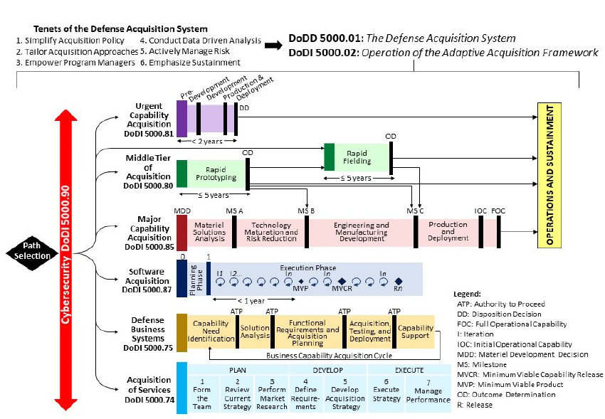
Figure 1-1. Adaptive Acquisition Framework .............................................................................................. 1
Figure 3-1. Major Capability Acquisition Life Cycle ................................................................................. 17
Figure 3-2. SoS SE Implementers’ View .................................................................................................... 18
Figure 3-3. Activities in Materiel Solution Analysis Phase ........................................................................ 23
Figure 3-4. Systems Engineering Activities in the Technology Maturation and Risk Reduction Phase .... 30
Figure 3-5. Systems Engineering Activities in the Engineering and Manufacturing Development Phase . 40
Figure 3-6. Systems Engineering Activities in the Production and Deployment Phase ............................. 51
Figure 3-7. Integration of Human Capability Considerations ..................................................................... 85
Figure 3-8. P&D and O&S HSI Challenges and Opportunities .................................................................. 87
Figure 3-9. MOSA and Modular System Interfaces ................................................................................. 101
Figure 3-10. Technical Reviews and Audits for the Major Capability Acquisition Life Cycle ................ 106
Figure 3-11. Software Acquisition Pathway Phase Illustration ................................................................ 137
Figure 3-12. Business Capability Acquisition Cycle ................................................................................ 152
Figure 3-13. HSI Opportunities in the Defense Business Systems Pathway ............................................ 153
Tables
40TUTable U40T2-1. Inputs Associated with Pre-MDD ................................................................................................ 4
40TUTable U40T2-2. Technical Outputs Associated with Pre-MDD ............................................................................ 6
40TUTable U40T3-1. Technical Maturity Points ......................................................................................................... 13
40TUTable U40T3-2. Key ME and SoS Considerations for Systems by Acquisition Phase ........................................ 20
40TUTable U40T3-3. Inputs Associated with MSA Phase ........................................................................................... 26
Contents
ENGINEERING OF DEFENSE SYSTEMS GUIDEBOOK
vii
40TUTable U40T3-4. Technical Outputs Associated with MSA Phase ....................................................................... 28
40TUTable U40T3-5. Inputs Associated with TMRR Phase ........................................................................................ 33
40TUTable U40T3-6. Technical Outputs Associated with TMRR Phase ..................................................................... 38
40TUTable U40T3-7. Inputs Associated with EMD Phase .......................................................................................... 45
40TUTable U40T3-8. Technical Outputs Associated with EMD Phase ....................................................................... 49
40TUTable U40T3-9. Inputs Associated with P&D Phase ........................................................................................... 54
40TUTable U40T3-10. Technical Outputs Associated with P&D Phase ...................................................................... 58
40TUTable U40T3-11. Inputs Associated with O&S Phase ......................................................................................... 61
40TUTable U40T3-12. Technical Outputs Associated with O&S Phase ...................................................................... 63
40TUTable U40T3-13. R&M Activities by Acquisition Phase .................................................................................... 70
40TUTable U40T3-14. M&Q Activities by Phase ........................................................................................................ 79
40TUTable U40T3-15. Minimum Points (When) to Assess Manufacturing Readiness ............................................... 82
40TUTable U40T3-16. System Safety Activities by Acquisition Phase ....................................................................... 91
This page is intentionally blank.
1 Purpose and Scope
ENGINEERING OF DEFENSE SYSTEMS GUIDEBOOK
1
1 32BPURPOSE AND SCOPE
The Engineering of Defense Systems Guidebook describes the activities, processes, and practices
involved in the development of Department of Defense (DoD) systems. The guidebook aligns
with the engineering disciplines covered in DoD Instruction (DoDI) 5000.88, Engineering of
Defense Systems, and focuses on recommended engineering best practices for the DoD Adaptive
Acquisition Framework (AAF) acquisition pathways (see Figure 1-1 and DoD Instruction
(DoDI) 5000.02, Operation of the Adaptive Acquisition Framework).
This guidebook is intended for Program Managers (PMs), Systems Engineers, and other defense
acquisition professionals and may be tailored for programs in any of the AAF pathways.
Programs can use the guidebook, along with other acquisition business resources, to plan and
execute program engineering activities across the system life cycle.
Source: DoDI 5000.02
0BFigure 1-1. Adaptive Acquisition Framework
Some of the information presented in this guidebook appeared previously in the Defense
Acquisition Guidebook (DAG) Chapter 3, Systems Engineering. DAG Chapter 3 has been
replaced by this document which expands on systems engineering (SE) and other engineering
guidance as applied to the acquisition pathways to support DoD acquisition programs. The DoD
Office of the Under Secretary of Defense for Research and Engineering (OUSD(R&E)), Deputy
Director for Engineering, prepared this guidebook in cooperation with subject matter experts
(SMEs) from the Military Services, defense agencies, industry, and academia.
2 Pre-Materiel Development Decision Engineering
ENGINEERING OF DEFENSE SYSTEMS GUIDEBOOK
2
2 33BPRE-MATERIEL DEVELOPMENT DECISION ENGINEERING
The objectives of the pre-Materiel Development Decision (MDD) effort are to obtain a clear
understanding of user mission capability needs, identify a range of technically feasible candidate
materiel solution approaches, consider near-term opportunities to provide a more rapid interim
response, and develop a plan for the next acquisition phase, including the required resources.
This knowledge supports the Milestone Decision Authority’s decision to:
1. Authorize entry into the acquisition life cycle to pursue a materiel solution.
2. Select the appropriate acquisition pathway and milestone dates.
3. Define the acquisition mandates that are to be tailored and waived based on schedule and
resources.
4. Define risk acceptance authorities for schedule, cost, performance, quality, security,
testing, training, maintenance, and human factors.
Programs achieve the pre-MDD objectives primarily through Mission Engineering (ME) and
other development planning activities. Development planning includes early engineering
analyses and technical planning that provide the foundation for informed investment decisions to
meet operational needs effectively, affordably, and sustainably. Programs should initiate
development planning activities in advance of the MDD, and continue throughout the Materiel
Solution Analysis (MSA) phase for Major Capability Acquisition (MCA) programs.
ME is an iterative analysis and multidisciplinary activity in the form of studies to analyze,
organize, and integrate current and emerging operational and system capabilities to achieve
desired warfighting mission effects. ME activities in the pre-MDD phase allow programs to
characterize trade space, risks, and mission interdependencies to support the start of the Analysis
of Alternatives (AoA).
Pre-MDD policy comes from two perspectives: the Joint Capabilities Integration and
Development System (JCIDS) defined in Chairman of the Joint Chiefs of Staff Instruction
(CJCSI) 5123 and the Defense Acquisition System (DAS) defined in DoD Directive (DoDD)
5000.01.
ME and Systems Engineering (SE) are essential during early phases in acquisition to ensure
programs ultimately deliver capabilities that meet the intended needs on time and on budget.
Mission understanding, design considerations, analyses, and associated activities during pre-
MDD are critical to determine feasibility and to characterize trade space (see the Systems
Engineering (SE) Guidebook for the definition of “design considerations”). During pre-MDD,
risks in mission concept and design may emerge that will need to be addressed before the MDD
and throughout the acquisition life cycle.
The pre-MDD effort has two important aspects: (1) Establish the ME reference materials that
guide materiel solution decisions throughout the life cycle, and (2) narrow the field of possible
2 Pre-Materiel Development Decision Engineering
ENGINEERING OF DEFENSE SYSTEMS GUIDEBOOK
3
solutions to a reasonable set that engineers analyze in the AoA. ME activities are critical to
refining the options. By defining and characterizing the mission(s), the capability gaps to be
addressed in the future fight, and potential warfighter concept solutions in a structured format,
the engineers and analysts help ensure the Service appropriately trades materiel solutions and
targets the evolving needs of the battlespace. ME studies help ensure a consistent understanding
of the constraints and technical feasibility so concept developers can eliminate initial ideas that
lack the potential to meet the need in a timely, sustainable, and cost-effective manner, while
ensuring the remaining range of alternatives is sufficiently broad for the AoA. The Systems
Engineer or Requirements Manager should engage with the end user or end user representatives
before the Joint Requirements Oversight Council (JROC) validates the Initial Capabilities
Document (ICD) or equivalent requirements document and associated operational architecture as
described in the SE Guidebook.
The Government Accountability Office (GAO) has found that “programs that considered a broad
range of alternatives tended to have better cost and schedule outcomes than the programs that
looked at a narrow scope of alternatives.” (See Government Accountability Office (GAO)-09-
665 Analysis of Alternatives, Page 6.) ME and AoA study teams can consider more alternatives
and design variations by using modeling and simulation tools.
The engineers performing pre-MDD work document all ME results so the PM and Systems
Engineer, when assigned, will benefit from an understanding of the basis of the mission, the
derived need (requirements), and the art of the possible (concepts/materiel solutions). In
addition, the program should continue to update the ME products to reflect the evolving mission
and threats. This ME analysis will then guide the PM and acquisition leadership at every
acquisition decision point to inform whether the materiel solution is still relevant to the
battlespace.
ME and SE personnel should use digital artifacts (models, simulations, etc.) from many
disciplines and across a hierarchy of perspectives that range from strategic, campaign, and
mission levels to analyze overall requirements, employment options, and battlespace efficacy.
The program should maintain, refine, and repurpose digital artifacts developed in early
acquisition phases for activities during later phases (e.g., engineering models can be used in
training simulations). Developing new digital artifacts can be costly. An option for new
development is to consider leveraging existing models and simulations, using various
interoperability standards to create needed capability. ME and SE personnel should consider how
to leverage models, simulations, and their interoperability as they plan for their use throughout a
program’s life cycle. Modeling and simulation can also support developmental test and
evaluation (DT&E) and operational test and evaluation (OT&E).
ME and SE personnel should continue to mature modeling and simulation tools used during the
pre-MDD phase and throughout the acquisition life cycle to represent the final system
configuration. Maintaining the models and simulations allows the program to perform additional
assessments as the system progresses.

2 Pre-Materiel Development Decision Engineering
ENGINEERING OF DEFENSE SYSTEMS GUIDEBOOK
4
Roles and Responsibilities
Often there is no assigned PM or Systems Engineer at this point in the system’s life cycle.
Instead, a designated Service representative (e.g., Requirements Manager) is leading the
activities prior to MDD. This leader is responsible for synthesizing the necessary information to
support a favorable decision. As a best practice, leadership should consider designating a Service
engineering representative to orchestrate or perform ME activities and support concept and
requirements definition and associated decisions in preparation for the MDD.
Digital engineering approaches including models and other digital representative products are
essential to understanding complex systems and interdependencies in this phase. Likewise, they
provide a means to explore concepts, system characteristics, and alternatives; open up the trade
space; facilitate informed decisions and assess overall system performance. Whether a program
adopts a robust digital engineering approach or not, ME analysis (see the ME Guide), models,
and simulations (SE Guidebook Section 2.2.1) are critical to quantitatively assess alternatives
and will also play a role throughout the program life cycle. The designated Service representative
should consider issuing a Request for Information to industry to help identify alternative
concepts, solutions, and their model equivalents.
Inputs
Table 2-1 summarizes the primary inputs associated with pre-MDD. Unlike the acquisition
pathways that follow, this period is the bridge between JCIDS and the DAS.
1BTable 2-1. Inputs Associated with Pre-MDD
Inputs for Pre-MDD
Mission definition artifacts:
Future time frame in which the mission is set
Future threats/adversary capabilities
Scenario details
Mission objectives, constraints, and measures of success
Expected and alternative force laydown(s)
Laws, mandates, policies, Executive Orders
Other program needs/failures
Lessons learned
Joint Warfare Capability definitions gaps; Service Component capability area definitions and gaps
USD(R&E) Technology Modernization roadmaps
Draft ICD or equivalent (See CJCSI 5123)
Product of Capability-Based Assessment or equivalent
Other analyses
Other prior analytic, experimental, prototyping and/or technology demonstration efforts may be provided by the
science and technology community
Results of market research: (1) to identify existing technologies and products; and (2) to understand potential
solutions, technologies and sources
Conference findings, federally funded research and development center input, strategy papers, 4-year outlooks
2 Pre-Materiel Development Decision Engineering
ENGINEERING OF DEFENSE SYSTEMS GUIDEBOOK
5
Activities
During pre-MDD, ME and SE activities include the following:
Achieve an in-depth understanding of the current and evolving operational capability
gaps defined in the ICD or equivalent requirements documentation, and identifying the
sources of the gap(s), which, if addressed by a materiel solution, could achieve the
needed capability
Identify an appropriate range of candidate materiel solutions from across the trade space
to meet the need
Identify near-term opportunities to provide a more rapid interim response to the
capability need
Work with the S&T community (across Government, industry, and academia) as well as
other collaborators to build the technical knowledge base for each candidate materiel
solution in the AoA Guidance including experimentation and prototyping
Analyze trade space to determine performance versus cost benefits of potential solutions
Plan for the technical efforts required during the next phase
Perform an early evaluation of risks associated with the alternatives to be analyzed in the
next phase
Work with requirements developers to ensure the quality of all operational requirements
Outputs and Products
The pre-MDD effort ends after a successful MDD review in which the Milestone Decision
Authority approves entry into the DAS.
The MDD review requires an ICD, or equivalent, that represents an operational capability need
validated in accordance with CJCSI 5123. The Joint Staff provides this document, which is
generally the output of a Capability-Based Assessment, ME analysis, or other studies. The
designated Service representative should have access to both the ICD and supporting studies.
Other technical information (such as models, simulations, etc.) may be useful for understanding
both the need and its context. The S&T community can contribute pertinent data and information
on relevant technologies, prototypes, experiments, or analysis.
The MDD is documented in an Acquisition Decision Memorandum (ADM) signed by the
Milestone Decision Authority. The ADM specifies the approved entry point, typically the MSA
phase for the MCA pathway. Pre-MDD outputs (Table 2-2) also include approved AoA
Guidance and an AoA Study Plan, which should be informed by ME and SE activities.

2 Pre-Materiel Development Decision Engineering
ENGINEERING OF DEFENSE SYSTEMS GUIDEBOOK
6
2BTable 2-2. Technical Outputs Associated with Pre-MDD
Technical Outputs from Pre-MDD
Configuration-controlled Mission Baseline including validated mission definition(s) the program will maintain and
use to measure mission efficacy of the materiel solution and a basis for future acquisition decision touchpoints.
Configuration controlled operational Concept Baseline including validated reference mission threads and
recommended candidate materiel solution concepts for further analysis/refinement in the next acquisition phase.
Validated mission threads:
o Of the mission if executed with expected forces in the future time frame. These are titled the “As-Is” mission
thread(s) and should highlight or illustrate the potential gap or shortfall.
o Of alternative concept (regardless of materiel solution) mission approaches. These are titled the “To-Be”
mission thread concept(s).
o Suggested Mission Engineering Threads that preliminarily incorporate promising Doctrine, Organization,
Training, Materiel, Leadership and Education, Personnel, Facilities, and Policy (DOTMLPF-P) considerations
and materiel solution concepts.
Informed advice to the ICD, or equivalent
Informed advice to the AoA Guidance and Study Plan (See AoA Guidebook (forthcoming).)
Informed advice to the plan and budget for the next phase, including support to the AoA and non-AoA technical
efforts required to prepare for the initial milestone review
Informed advice to the ADM
All potential materiel solutions pass through an MDD before entering the DAS; however, the
Milestone Decision Authority may authorize entry at any point in the acquisition life cycle based
on the solution’s technical maturity and risk. If the Service-recommended entry point into the
MCA pathway is beyond the MSA phase, for example, partway through the Technology
Maturation and Risk Reduction (TMRR) phase, the program should document evidence that all
MSA and TMRR phase-specific entrance criteria and statutory requirements are met and that the
solution’s technical maturity supports entry at the point in the phase being proposed. Technical
risk has several elements: mission risk, technology risk, engineering risk, and integration risk.
The Service or designated representative should ensure the soundness of supporting technical
information and plans in order to inform the Milestone Decision Authority’s decision. The
technical plan and budget presented at the MDD should reflect the full range of activities
required in the next phase.
2.1 35BPre-MDD Mission Engineering Reviews
2.1.1 43BMission Review
DoD Joint Publication 3-0 (Joint Operations) defines a “mission” as the task, together with the
purpose, that clearly indicates the action to be taken and the reason thereby. The mission
definitions (validated by the Joint Staff and Combatant Commands) are the fundamental basis for
evaluating materiel solutions and trades. The Mission Review should ensure that the definition of
the future mission(s), either today or in the future, and the desired mission outcomes (measured
2 Pre-Materiel Development Decision Engineering
ENGINEERING OF DEFENSE SYSTEMS GUIDEBOOK
7
by mission metrics) have been adequately established and are sufficiently defined in order to
conduct Mission Engineering (see the ME Guide). In accordance with DoDI 5000.88, a
USD(R&E) representative will chair Mission Reviews for joint missions and the applicable Service
representative will chair Mission Reviews for Service-specific missions.
The Mission Review should establish and place under configuration control a validated and well-
articulated set of Mission Baselines. The Mission Baselines should include mission definitions
and time frames of interest in which the missions are set. Mission definitions include scenario
setting, threats, allies/partners, mission assumptions, mission objectives, constraints, mission
measures of success, and expected force laydown (i.e., position and qualities of platforms or
systems). These terms and the ME methodology are further described in the ME Guide.
There may be multiple (or a family of) Mission Baselines but with varying elements of the
mission definition – for example a change in the time frame of interest (i.e., 2025, 2030, 2035),
or multiple vignettes. The family of Mission Baselines should evolve to reflect the changing
threats, Defense Planning Guide, and National Defense Strategy. The baseline(s) should be
updated and revised at a minimum every 2 years to support the Future Years Defense Program
(FYDP) cycle and in sufficient time to guide ME activities in support of OUSD R&E investment
and DAS-based decisions. The Mission Review should trace the mission definition to the Joint
Capability Areas and provide scenario details to guide analyses of potential concept,
technological, DOTMLPF-P and materiel solutions.
Roles and Responsibilities
Under Secretary of Defense for Research and Engineering (USD(R&E))
o Provide guidance for defining components and details of Mission Baselines and
associated mission definitions
o Coordinate access to appropriate data repository(ies) and instructions
(upload/download, tagging, configuration control, etc.) to share Mission Review
products (i.e., Mission Baseline artifacts and other relevant data/material). Products
may include architectures, models, etc.
o Provide, along with Joint Staff, guidance and criteria for conduct of the Mission Review
o Chair, or co-chair with Joint Staff, Mission Reviews for joint missions
Joint Staff – for joint missions
o Host, or co-host with OUSD(R&E), Mission Reviews
o Provide validated mission definitions and baselines with support of combatant
commands (COCOMs)
o Include representatives of OUSD(R&E) and OUSD for Acquisition and Sustainment
(OUSD(A&S))
o Provide for sharing Mission Review products across the Department following
instructions and repository guidance from OUSD(R&E)
2 Pre-Materiel Development Decision Engineering
ENGINEERING OF DEFENSE SYSTEMS GUIDEBOOK
8
Services/Components – for Service-specific missions
o Host Mission Review
o Derive mission definitions from joint mission definitions and baselines
o Provide validated mission definitions and baselines with support of COCOMs
o As needed, include representatives of OUSD(R&E) and OUSD(A&S) in Mission
Reviews
o Provide for sharing Mission Review products across the Department
Inputs and Review Criteria
Mission definition(s)
o Time frame of intended mission(s) (year of conflict)
o Known strategic gaps in capability
o Traceability to Defense Planning Guide, Joint Capability Areas, Joint Task Lists, or
Service tasks lists
o Environmental conditions, geopolitical setup, expected threat, etc.
Assumptions and constraints that should be used for analyses
Mission measures of success
o Objectives of the mission in quantifiable terms
o Definitions of measures of effectiveness (MOEs) or other measures of performance
(MOPs) as well as key target values for these measures
Trades that are needed to inform mission refinement
Other interrelated Mission Baseline(s)
Outputs and Products
Documented Mission Baseline(s) that encompass the agreements and final products to
address the inputs and review criteria of the Mission Review
Traceability to Defense Planning Guide, Joint Capability Areas, and Joint Tasks Lists
o Documented capability gaps
Data or products needed to guide concept exploration and DOTMLPF-P evaluations to
support maturation of the Concept Design
o Questions requested by leadership to inform trades and support decisions
o Analyses needed to refine the mission definition(s)
All products should be made readily available to the Office of the Secretary of Defense
(OSD) and other DoD Components for use and integration across mission definitions
2 Pre-Materiel Development Decision Engineering
ENGINEERING OF DEFENSE SYSTEMS GUIDEBOOK
9
2.1.2 44BConcept Design Review
In accordance with DoDI 5000.88, a Concept Design Review (CoDR) will be conducted before
the MDD where the initial Concept Baseline(s) will be established. The CoDR will be chaired by a
USD(R&E) representative for joint missions and by the applicable Service representative for
Service-specific missions. The review is the culmination of concept exploration and DOTMLPF-
P evaluations to address preliminary solution trades to meet mission needs. The CoDR should be
a multidisciplined review of the potential joint warfare concepts, Service-specific concepts, and
DOTMLPF-P considerations to address the needs of the Mission Baseline. The review should
evaluate the rigor used to identify the candidate alternatives (both materiel and non-materiel) that
should be further explored to address the baseline missions. The Service representative informs
the CoDR by performing top-level ME analyses of future concepts and exploring integrated joint
force possibilities. These analyses should provide balanced and quantifiable insight to help
leadership rank order candidate concepts, non-materiel, and likely materiel (integrated joint,
service agnostic, as well as partner alliance) solutions. The CoDR products will inform the MDD
or provide guidance for non-materiel action by COCOMs.
The CoDR should establish the operational Concept Baseline and include recommended
candidate materiel alternatives and an update to the Mission Baseline materials (i.e., the mission
definition(s)). The Service representatives document the Concept Baseline to depict the mission
definition, the future time frame in which it is set, threats, scenario specifics, mission objectives,
constraints, mission measures of success, and expected force laydown (see the ME Guide). The
CoDR should also include a review of the supporting technology roadmaps and prototyping or
experimentation efforts (plans and results) that enable each of the concepts and alternatives. The
Service presents these candidates at the MDD to shape what the SE and ME team will further
evaluate as part of the AoA. The CoDR should include a technical sufficiency evaluation of the
AoA Study Guidance to ensure it is grounded to the Mission Baseline, it equally considers
Service-specific and joint alternatives, and it addresses the candidate “To-Be” mission thread(s)
resulting from the CoDR.
Roles and Responsibilities
USD(R&E)
o Provide guidance and details for establishing the Concept Baseline
o Provide guidance and criteria on the conduct of the CoDR
o For non-delegated studies, perform ME analyses to inform the Concept Baselines and
alternatives to support the CoDR and MDD
o Update and provide technology and prototyping or experimentation roadmaps
o Provide procedures, infrastructure, or a repository to share elements of Concept
Baselines, candidate alternatives, and decisions
2 Pre-Materiel Development Decision Engineering
ENGINEERING OF DEFENSE SYSTEMS GUIDEBOOK
10
USD(A&S)
o Provide DAS portfolio capability performance and schedules
Joint Staff – for joint missions
o Provide updated validated mission definitions and baselines with support of CCMDs
o Provide Joint Warfighting Concept roadmaps/architectures
o Provide for sharing ME and CoDR products across the Department
o Perform a Capability Portfolio Review as part of the CoDR if it was not conducted
separately
Services or Components
o Perform ME analyses to inform the Concept Baselines and alternatives to support the
CoDR and MDD
o Provide updated validated mission definitions and baselines with support of CCMDs
o As needed, include representatives of OUSD(R&E) and OUSD(A&S)
o Provide for sharing ME and CoDR products across the Department
Inputs and Review Criteria
Mission Baseline(s), including updated mission definitions informed by evolving mission
and threats
Technology, Prototyping and Experimentation roadmaps, and Joint Warfighting Concept
architectures
Program of Record (DAS portfolio) capability performance projections and schedules
ME analyses
Outputs and Products
Updated Mission Baseline(s)
Initial Concept Baseline(s), including:
o Identification of candidate concepts and alternatives that could meet the mission
objectives (initial rank ordering of the most promising solutions)
o Framing assumptions
o Concept Design Trade Matrix
o Concept of Operations (CONOPS), or Operational Mode Summary/Mission Profile
o Mapping to contributing technology and prototyping/experimentation roadmaps
o Program risk assessment (with technology development and other risk mitigation
activities, appropriate affordability targets, and initial schedule basis)
2 Pre-Materiel Development Decision Engineering
ENGINEERING OF DEFENSE SYSTEMS GUIDEBOOK
11
o Initial Security/Cybersecurity/Protection Assessment (identification of Critical
Technical Parameters, etc.)
o Validated reference mission threads
The mission, if executed, with expected forces in the future time frame. These are
titled the “As-Is” mission thread(s) and should highlight or illustrate the potential
gap/shortfall.
Alternative concept (material solution agnostic) mission approaches. These are
titled the “To-Be” mission thread concept(s).
Suggested Mission Engineering Threads that preliminarily incorporate promising
DOTMLPF-P considerations and material solution concepts for further
analysis/refinement in the next acquisition phase.
ME-informed Capability-Based Assessment
ICD
Informed DAS alternative pathway selection (quantitatively linking the mission
definition, time frame, gap and potential solution maturity level to the appropriate
acquisition model)
Updated AoA study guidance that incorporates USD(R&E) and ME-based direction

3 Engineering Guidance for the Acquisition Pathways
ENGINEERING OF DEFENSE SYSTEMS GUIDEBOOK
12
3 34BENGINEERING GUIDANCE FOR THE ACQUISITION PATHWAYS
3.1 36BOverview
Engineering provides the technical foundation for all DoD acquisition activities regardless of
Acquisition Category (ACAT) or acquisition pathway. In addition to the Acquisition Strategy,
PMs and systems engineers should develop an engineering approach that matches the acquisition
pathway processes, reviews, documents, and metrics to the character and risk of the capability
being acquired. Although this guidance document employs some terminology mainly applicable
to the MCA pathway, the principles and practices should be applied, as appropriate and tailored,
to all DoD system development. While an MDAP or major system using the MCA pathway will
typically employ the majority of activities and events described in this document, it is prudent for
the PM and Systems Engineer to consider all of these activities and events for their respective
program regardless of pathway.
3.2 37BMajor Capability Acquisition
Major Capability Acquisitions (MCAs) follow a process designed to support MDAPs, major
systems, and other complex acquisitions. The MCA approach includes steps to analyze, design,
develop, integrate, test, evaluate, produce, and support. Programs tailor acquisition and product
support processes, reviews, and documentation (including digital artifacts and models as
representations of reality) depending on the program size, complexity, risk, urgency, and other
factors. Programs may acquire software-intensive components via the Software Acquisition
pathway and integrate the products and align dependencies into the MCA program.
3.2.1 45BSystems Engineering
3.2.1.1 Life Cycle Expectations
The SE described in this document spans the acquisition life cycle and is based on DoDD
5000.01, DoDI 5000.02; DoDI 5000.85, Major Capability Acquisition; and DoDI 5000.88.
Programs should tailor the SE content to fit the technology maturity, risks, interdependencies,
related characteristics, and context for the program or the system of interest. The following
sections identify the SE activities, processes, inputs, outputs, and expectations during each
acquisition phase and for each technical review and audit.
Acquisition milestones and SE technical reviews and audits serve as key points throughout the
life cycle to evaluate significant achievements and assess technical maturity and risk. Table 3-1
identifies the objectives of each SE assessment and the technical maturity point marked by each
review. The MDD review is the entry point into the MCA process and is mandatory for all
programs in accordance with DoDI 5000.85, Section 3.5.a. Depending on the maturity of the
preferred materiel solution, at the MDD review the Milestone Decision Authority officially
designates the MSA phase as the entry point or may designate the entry point as Milestone B, or
C as appropriate. The Milestone Decision Authority documents the decision in a signed ADM

3 Engineering Guidance for the Acquisition Pathways
ENGINEERING OF DEFENSE SYSTEMS GUIDEBOOK
13
published immediately after the MDD event. Since the review milestone must be consistent with
the maturity of the preferred materiel solution, entry at any milestone requires evidence of the
associated solution maturity, as summarized in Table 3-1.
Department experience (e.g., GAO Report 12-400SP) demonstrates that successful programs use
knowledge-based product development practices that include steps and techniques to gather and
curate knowledge to confirm the program’s technologies are mature, their designs are stable, and
their production processes are in control. Successful materiel developers ensure programs
acquire a high level of knowledge about a system at key junctures in development. Table 3-1
summarizes the concept of technical maturity points.
3BTable 3-1. Technical Maturity Points
Technical Maturity Points
DoD Acquisition
Milestone/Decision
Point and Technical
Review/Audit
Objective
Technical Maturity Point
Additional Information
Materiel Development
Decision (MDD)
Decision to assess
potential materiel
solutions and
appropriate phase for
entry into acquisition
life cycle.
Capability gap met by
acquiring a materiel
solution.
Technically feasible solutions
have the potential to effectively
address a validated capability
need. Technical risks understood.
Alternative Systems
Review (ASR)
Recommendation
that the preferred
materiel solution can
affordably meet user
needs with
acceptable risk.
System parameters
defined; balanced with
cost, schedule and risk.
Initial system performance
established and plan for further
analyses (e.g., assessing
technical maturity and associated
risks) supports Milestone A
criteria.
Milestone A
Decision to invest in
technology
maturation and
preliminary design.
Affordable solution found
for identified need with
acceptable technology risk,
scope, and complexity. 10
USC 2366a certification, if
applicable.
Affordability goals identified and
technology development plans,
time, funding, and other resources
match customer needs.
Prototyping and end-item
development strategy for TMRR
phase focused on key technical
risk areas.
System Requirements
Review (SRR)
Recommendation to
proceed into
development with
acceptable risk.
Level of understanding of
top-level system/
performance requirements
is adequate to support
further requirements
analysis and design
activities.
Government and contractor
mutually understand system
/performance requirements
including:
(1) the preferred materiel solution
(including its support concept)
from the MSA phase;
(2) plan for technology and
manufacturing maturation; and
(3) maturity of interdependent
systems.

3 Engineering Guidance for the Acquisition Pathways
ENGINEERING OF DEFENSE SYSTEMS GUIDEBOOK
14
Technical Maturity Points
DoD Acquisition
Milestone/Decision
Point and Technical
Review/Audit
Objective
Technical Maturity Point
Additional Information
System Functional
Review (SFR)
Recommendation
that functional
baseline satisfies
performance
requirements and to
begin preliminary
design with
acceptable risk.
Functional baseline
established and under
formal configuration
control. System functions
in the system performance
specification decomposed
and defined in
specifications for lower
level elements, that is,
system segments and
major subsystems.
Functional requirements and
verification methods support
achievement of performance
requirements. Acceptable
technical risk of achieving
allocated baseline. See SE
Guidebook Section 4.1.6,
Configuration Management
Process for a description of
baselines.
Capability
Development
Document (CDD)
Validation
Requirements
validation authority
action. Provides a
basis for preliminary
design activities and
the preliminary
design review (PDR).
Major cost and
performance trades have
been completed and
enough risk reduction has
been completed to support
a decision to commit to the
set of requirements (i.e.,
CDD or equivalent)
Support preparation for CDD
validation by performing systems
engineering trade-off analysis with
Modular Open Systems Approach
(MOSA) considerations
addressing relationships of cost,
requirements, design, and
schedule. Once validated, a
Configuration Steering Board
assumes responsibility to review
all requirements changes and any
significant technical configuration
changes for ACAT I and IA
programs in development,
production, and sustainment that
have the potential to result in cost
and schedule impacts to the
program.
Preliminary Design
Review (PDR)
Recommendation
that allocated
baseline satisfies
user requirements
and developer ready
to begin detailed
design with
acceptable risk.
Allocated baseline
established such that
design provides sufficient
confidence to proceed with
detailed design. Baseline
also supports 10 USC
2366b certification, if
applicable.
Preliminary design and
appropriate architecture products
support capability need and
affordability goals and/or caps
achievement. For MDAPs,
Secretary of Defense (SecDef)
approved program cost, fielding,
and performance goals are
achievable. See SE Guidebook
Section 4.1.6. Configuration
Management Process for a
description of baselines.

3 Engineering Guidance for the Acquisition Pathways
ENGINEERING OF DEFENSE SYSTEMS GUIDEBOOK
15
Technical Maturity Points
DoD Acquisition
Milestone/Decision
Point and Technical
Review/Audit
Objective
Technical Maturity Point
Additional Information
Development Request
for Proposal (RFP)
Release Decision
Point
Determination that
program plans are
affordable and
executable and that
the program is ready
to release RFPs for
Engineering and
Manufacturing
Development (EMD)
and/or for Low-Rate
Initial Production
(LRIP).
Systems engineering
trades completed and have
informed program
requirements. Competitive
and risk reduction
prototyping and the
development of the
preliminary design have
influenced risk
management plans and
should-cost initiatives.
The RFP reflects the program’s
plans articulated in the draft (as
defined in DoDI 5000.88, Section
3.9) Acquisition Strategy and
other draft, key planning
documents such as the Systems
Engineering Plan (SEP), Program
Protection Plan (PPP), Test and
Evaluation Master Plan (TEMP),
and Life Cycle Sustainment Plan
(LCSP). The RFP also includes a
MOSA Strategy that clearly
describes the modular open
system approach to be used for
the program (as described in
DoDI 5000.88, Section 3.7)
Milestone B
Decision to invest in
product development,
integration, and
verification as well as
manufacturing
process
development;
decision on LRIP
quantity.
Critical technologies
assessed able to meet
required performance and
are ready for further
development. Resources
and requirements match.
Maturity, integration, and
producibility of the preliminary
design (including critical
technologies) and availability of
key resources (time, funding,
other) match customer needs.
Should-cost goals defined. Clearly
define modular system interfaces
between the major system
platform and major system
components and between major
system components and modular
platforms. Ensure that the MOSA
Strategy ensures there are
standardized interfaces and
appropriate arrangements for
obtaining necessary IP rights
have been addressed and
implemented (as described in
DoDI 5000.88, Section 3.7).
Critical Design
Review (CDR)
Recommendation to
start fabricating,
integrating, and
testing test articles
with acceptable risk.
Product design is stable.
Initial product baseline
established.
Product baseline is initially
established by the system
detailed design documentation;
affordability/should-cost goals
confirmed. Government assumes
control of initial product baseline
as appropriate. See SE
Guidebook Section 4.1.6.
Configuration Management
Process for a description of
baselines.

3 Engineering Guidance for the Acquisition Pathways
ENGINEERING OF DEFENSE SYSTEMS GUIDEBOOK
16
Technical Maturity Points
DoD Acquisition
Milestone/Decision
Point and Technical
Review/Audit
Objective
Technical Maturity Point
Additional Information
System Verification
Review
(SVR)/Functional
Configuration Audit
(FCA)
Recommendation
that the system as
tested has been
verified (i.e., product
baseline is compliant
with the functional
baseline) and is
ready for validation
(operational
assessment) with
acceptable risk.
System design verified to
conform to functional
baseline.
Actual system (which represents
the production configuration) has
been verified through required
analysis, demonstration,
examination, and/or testing.
Synonymous with system-level
FCA. See SE Guidebook Section
4.1.6. Configuration Management
Process for a description of
baselines.
Production
Readiness Review
(PRR)
Recommendation
that production
processes are mature
enough to begin
limited production
with acceptable risk.
Design and manufacturing
are ready to begin
production.
Production engineering problems
resolved and ready to enter
production phase.
Milestone C and
Limited Deployment
Decision
Decision to produce
production-
representative units
for operational test
and evaluation
(OT&E) and/or
decision that
increment of
capability is ready for
Limited Deployment.
Manufacturing processes
are mature enough to
support LRIP (and/or
Limited Deployment) and
generate production-
representative articles for
OT&E. Increment of
capability has stable
design.
Production readiness meets cost,
schedule, and quality targets.
Begin initial deployment and/or
deploy increment of capability.
Physical
Configuration Audit
(PCA)
Recommendation to
start full-rate
production and/or full
deployment with
acceptable risk.
Product baseline
established. Verifies the
design and manufacturing
documentation, following
update of the product
baseline to account for
resolved OT&E issues,
matches the physical
configuration.
Confirmation that the system to be
deployed matches the product
baseline. Product configuration
finalized and system meets user’s
needs. Conducted after OT&E
issues are resolved. See SE
Guidebook Section 4.1.6.
Configuration Management
Process for a description of
baselines.
Full-Rate Production
Decision Review (FRP
DR) or Full
Deployment Decision
Review (FDDR)
Decision to begin full-
rate production
and/or decision to
begin full
deployment.
Manufacturing processes
are mature and support
full-rate production and/or
capability demonstrated in
operational environment
supporting full deployment
(i.e., system validated
through OT&E).
Delivers fully funded quantity of
systems and supporting materiel
and services for the program or
increment to the users.
3 Engineering Guidance for the Acquisition Pathways
ENGINEERING OF DEFENSE SYSTEMS GUIDEBOOK
17
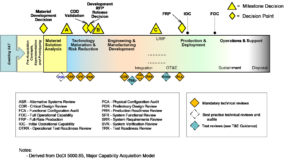
Figure 3-1 provides the end-to-end perspective and the integration of SE technical reviews and
audits across the system life cycle.
4BFigure 3-1. Major Capability Acquisition Life Cycle
The Systems Engineer supports the PM in developing and implementing a technical program
strategy. SE processes within this technical program strategy help deliver capabilities that meet
warfighter needs within cost and schedule by balancing end-user needs, design considerations,
resource constraints, and risk. The Systems Engineer uses technical reviews and audits to assess
whether the program reaches preplanned technical maturity points during the acquisition life
cycle as the system and system elements mature. The Systems Engineer facilitates the program’s
ability to achieve the entry criteria for these points by identifying and mitigating technical risks
leading up to reviews and audits (see the DoD Risk, Issue, and Opportunity Management Guide
for Defense Acquisition Programs.)
The Systems Engineer should strive to ensure consistency among analyses that support key
decision and transition points throughout a program’s life cycle. For instance, models,
simulations, tools, and data should be integrated into the SE activities and reused to the greatest
extent possible (see SE Guidebook Section 2.2.1. Models and Simulations and Section 2.2.2
Digital Engineering). This knowledge forms part of the authoritative source of truth for the
system, as well as the basis for the Systems Engineer’s recommendations to the PM regarding
how to technically proceed with the program.

3 Engineering Guidance for the Acquisition Pathways
ENGINEERING OF DEFENSE SYSTEMS GUIDEBOOK
18
3.2.1.2 Systems of Systems and Mission Engineering
Whether or not a system is acknowledged as a system of systems (SoS), nearly all DoD systems
function as part of an SoS to deliver a necessary capability to the user. SoS engineering is an
ongoing, iterative process, as shown in the SoS SE Implementers’ View in Figure 3-2. The
backbone of SoS SE implementation is a continuous ME analysis that considers changes from
the broader operational mission environment as well as feedback from the ongoing engineering
process.
As previously mentioned, ME is an iterative analysis and multidisciplinary activity to analyze,
organize, and integrate current and emerging operational and system capabilities to achieve
desired warfighting mission effects. Implementing a digital engineering technical approach at the
beginning of a program’s life cycle may greatly facilitate this iterative ME approach.
ME provides the quantitative basis for developing and evolving SoS architectures, evaluating
contributions of constituent systems within the SoS, and guiding changes to achieve mission
success. Ensuring a robust ME approach provides structure to the maturation of systems within
the SoS, which are typically on different life cycle timelines, and helps ensure systems and
Concept of Operations, Operational Mode Summaries, and Mission Profiles
(CONOPS/OMS/MP) adapt and integrate to meet the evolution of the mission.
5BFigure 3-2. SoS SE Implementers’ View
ME should address the end-to-end behavior of the ensemble of systems, addressing the key
issues that affect this end-to-end behavior with particular emphasis on integration and
interoperability. ME planning and implementation should consider and leverage the development
plans of the individual systems in order to balance SoS needs with individual system needs. ME
analyses help provide an input in the development of an architecture and balance the technical
management of the SoS. ME provides a basis for digital engineering, modeling and simulation,
and MOSA to rapidly adapt as adversaries change. Refer to the SE Guidebook, Section 3, for
additional information on SoS.
3 Engineering Guidance for the Acquisition Pathways
ENGINEERING OF DEFENSE SYSTEMS GUIDEBOOK
19
Consideration of SoS in SE for Individual Systems
Most acquisition programs address the development or major upgrade of individual systems (in
contrast to SoS). Understanding the SoS context(s) of the system (including use in multiple
operational environments) is critical to developing requirements for the system so, when
delivered, the system operates effectively in user operational environments. From the JCIDS
Capability-Based Assessment through sustainment activities, it is important to recognize how the
system context influences system requirements. An up-to-date CONOPS/OMS/MP for the
system is essential to understanding the system context, notably, mission and task threads and
data exchanges that have an impact on the system. Systems Engineers of individual systems
should collaborate to ensure the program addresses SoS considerations and risks throughout the
acquisition life cycle:
Identify system dependencies and interoperability needs (see SE Guidebook, Section
5.12. Interoperability and Dependencies) through ME analysis.
Factor these dependencies into the development of system concepts, requirements, and
risks.
Address these dependencies through trade analysis, system architecture and design,
interface development and management, and verification and validation.
Clearly define modular system interfaces between major system platform and major
system components, between major system components, and between major system
platforms (see DoDI 5000.88 Section 3.7).
From an individual system perspective and from the SoS perspective, PMs and Systems
Engineers may find it difficult to balance the acquisition objectives and strategies for a given
system with those of other systems.
DoD engineers have determined the following as best practice:
Closely monitor interdependent programs, with checkpoints at scheduled design reviews
to assess program progress, assess related risks and determine actions to mitigate
potentially negative impacts.
Allow technical representatives from each system participate in one another’s System
Functional Review (SFR), Preliminary Design Review (PDR), and Critical Design
Review (CDR).
Establish a senior governance body to provide a forum for discussion and decision. This
forum should address functional capabilities, technical plans, configuration management
and strategies with respect to interfaces, interdependences, risks, and risk mitigation. It is
critical that the program address all equities and make collective decisions that can be
implemented as changes to a system’s configuration.

3 Engineering Guidance for the Acquisition Pathways
ENGINEERING OF DEFENSE SYSTEMS GUIDEBOOK
20
In all cases the programs should support an ME methodology (as described in the ME Guide) to
fully examine the relationships and contributions of the system and SoS relative to a mission
context and in a selected mission thread(s).
Table 3-2 lists ME and SoS considerations for systems at each stage of acquisition. At each
phase, the SE approach to addressing SoS-related dependencies should be addressed in the SEP.
6BTable 3-2. Key ME and SoS Considerations for Systems by Acquisition Phase
Acquisition Phase
Considerations
Pre-Materiel
Development
Decision (Pre-MDD)
Role of the system in supporting a mission capability, including relationship to other
systems in the SoS that support that capability
Mission Architecture with various scenarios (e.g., mission thread) of capability gap in
context of specified mission
Mission threads that describe the flow of tasks/activities in relationship to other
systems and context
Identification of relevant Joint DOTMLPF-P
Identification of stakeholders
Provided by the ME analysis and the evidence provided at MDD
Materiel Solution
Analysis (MSA)
In the AoA, consider the alternatives in the context of the larger SoS supporting the
capability; use ME processes as part of the AoA
Include a SoS context for the ME analysis that includes the preferred materiel
solution: evaluate dependencies and relationships with other systems, modular
system interfaces, modular systems, and technical risks based on SoS considerations
to be addressed in TMRR
Identify non-materiel changes needed to implement a specific materiel solution, e.g.
changes to tools, techniques and procedures to enable the SoS capability
AoA criteria or results relevant to SoS dependencies or modular system interfaces
Identify and define system dependencies and modular system interfaces that
influence system requirements
Initial management plans with supporting memoranda of agreements (MOAs),
including draft Interface Control Agreements for collaborations with other systems in a
SoS
System Safety Engineering Activities (e.g. Physical Hazard Analysis (PHL), System
Safety Management Plan, etc.) to assess materiel solutions by identifying inherent
hazard risks and develop criteria to define key objectives for the SS Program
Risks associated with SoS dependencies (both programmatic and technical) and
interoperability requirements, including System Safety, environment, occupational
health, and security risks to be accepted by Joint Authorities
Modeling and simulation tools to support trade space analysis and manufacturing
feasibility evaluations
SoS-related requirements in draft system performance specification or pre-MS A RFP
MOAs with key parties in SoS dependencies or relationships

3 Engineering Guidance for the Acquisition Pathways
ENGINEERING OF DEFENSE SYSTEMS GUIDEBOOK
21
Acquisition Phase
Considerations
Technology
Maturation and Risk
Reduction (TMRR)
Assess the technical approaches and risks for addressing system requirements
including considerations for the system as a component operating in a SoS context
(including dependencies, interoperability and modular interfaces)
Address considerations of changes needed in other systems for the systems in
acquisition to meet capability objectives
An interface management plan, including MOAs and a schedule, that is a part of a
configuration management plan, including Interface Control Agreements
Risks associated with SoS dependencies (both programmatic and technical) and
interoperability requirements, including System Safety, environment, and
occupational health, and security risks to be accepted by Joint Authorities
Models and simulation tools used to support early assessment of requirement trade
space, performance specifications, operational suitability and affordability, and
manufacturing processes
Initiation of a digital engineering ecosystem with digital artifacts to support the
system’s life cycle and program decision making
Output of studies which validate the technical fit and operational suitability of the
system under development within the SoS
Final interface specifications
Progress with respect to schedule and plan milestones
Progress with respect to expected performance
Engineering and
Manufacturing
Development (EMD)
Develop, verify, and validate the detailed design that addresses system requirements,
considering the SoS context including recognized dependencies and modular system
interfaces
Interface documentation, digital artifacts, test plans and test reports
Update to MOAs with system’s dependencies
Risks associated with SoS dependencies (both programmatic and technical) and
interoperability requirements, including System Safety, environment, and
occupational health, and security risks to be accepted by Joint Authorities
Digital engineering ecosystem and implementation plan (models, simulations, etc.) to
support concurrent and collaborative engineering, reduce defects and rework costs,
accelerate the development schedule, improve system design, and software reliability
and quality
Successful development and test of interfaces
Verification and compliance of modular system interfaces with widely supported and
consensus-based standards (if available and suitable)
Progress with respect to SoS schedule and plan milestones
Progress with respect to expected performance
Production and
Deployment (P&D)
and Operations and
Support (O&S)
Verify the as-built system and interdependent systems’ interfaces meet standards and
specifications and support operational needs
Support effective system operation in a SoS context
Test reports
Digital artifacts (models, simulations, etc.) reflect the production configuration to
rapidly evaluate changing threats, explore solution space, and support design reuse
Mature digital engineering ecosystem to support future system enhancements and
upgrades, sustainment activities, decision making, and assessments such as mission
engineering
3 Engineering Guidance for the Acquisition Pathways
ENGINEERING OF DEFENSE SYSTEMS GUIDEBOOK
22
3.2.1.3 Systems Engineering Activities in Life Cycle Phases
This section describes the objectives and technical activities typically performed in each of the
five life cycle phases of the MCA pathway (MSA, TMRR, EMD, P&D, and Operations and
Support (O&S)). For each phase, the description includes the roles and responsibilities of a
Systems Engineer in the program office, inputs normally required to constrain the technical
activities, activities the Systems Engineer performs, and outputs and products of the phase.
Although this section mentions technical reviews and audits, more details are covered in the SE
Guidebook Section 3, Technical Reviews and Audits.
3.2.1.3.1 Materiel Solution Analysis Phase
The objective of the MSA phase is to select and adequately describe a preferred materiel solution
to satisfy the phase-specific entrance criteria for the next program milestone designated by the
Milestone Decision Authority. Before completing the MSA Phase, the Component Acquisition
Executive (CAE) selects a PM and establishes a program office to complete the necessary
actions associated with planning the acquisition program. Usually, but not always, the next
milestone is a decision to invest in technology maturation, risk reduction activities, and
preliminary design in the TMRR phase. During the MSA phase the SE team develops several
products including the following:
A system model or architecture that captures operational context and envisioned
concepts, describes the system boundaries and interfaces, and addresses operational and
functional requirements
Foundation of the program’s digital engineering ecosystem
Preliminary system performance specification that defines the performance of the
preferred materiel solution
Advice to the PM regarding what components of the system should be prototyped, why,
and how
The MSA phase has two major blocks of activity: (1) the AoA led by the Director, Cost Analysis
and Program Evaluation and conducted by a designated DoD Component and (2) the post-AoA
operational analysis and concept engineering to prepare for a next program milestone designated
by the Milestone Decision Authority (Figure 3-3).

3 Engineering Guidance for the Acquisition Pathways
ENGINEERING OF DEFENSE SYSTEMS GUIDEBOOK
23
7BFigure 3-3. Activities in Materiel Solution Analysis Phase
During the MSA phase, the program team identifies a materiel solution to address current and
evolving user capability gaps partially based on the AoA. Once the Service sponsor selects a
preferred materiel solution, the program team prepares for the next life cycle phase by focusing
engineering and technical analysis on this solution to ensure the development plans, schedule,
funding, and other resources match customer needs and the complexity of the preferred materiel
solution. The program should integrate SE activities with MSA phase-specific test, evaluation,
logistics, and sustainment activities identified in the T&E Enterprise Guidebook (forthcoming).
and Sustainment Guidebook (forthcoming).
The AoA team considers a range of alternatives and evaluates them from multiple perspectives
as directed by the AoA Guidance and AoA Study Plan. The guidance and plan should address
engineering considerations including technical risk. For MDAPs, the guidance and plan also
should include considerations of evolutionary acquisition, digital engineering, prototyping, and
MOSA, pursuant to 10 USC 2446b.(b).
The objective of the AoA is to analyze and characterize each alternative (or alternative approach)
relative to the others. The AoA does not result in a recommendation for a preferred alternative; it
provides information that the Service sponsor uses to select which materiel solution to pursue.
The Systems Engineer should participate in the AoA to conduct ME activities as indicated in the
ME Guide, including analyzing the impact of performance, technology, and manufacturing
feasibility on mission efficacy.
3 Engineering Guidance for the Acquisition Pathways
ENGINEERING OF DEFENSE SYSTEMS GUIDEBOOK
24
Using the AoA results, the Service sponsor may conduct additional engineering analysis to
support the selection of a preferred materiel solution. As the Milestone Decision Authority
selects preferred solutions, the Service sponsor will further mature them in preparation for the
next program milestone. After the AoA, Systems Engineers establish the technical performance
requirements consistent with the draft CDD, required at the next program milestone designated
by the Milestone Decision Authority. These requirements form the basis for the system
performance specification placed on contract for the TMRR phase; they also inform plans to
mitigate risk in the TMRR phase.
In the MSA phase, the DoD Component combat developer (e.g., Requirements Manager)
prepares a CONOPS/OMS/MP, consistent with the validated/approved capability requirements
document, typically an ICD. The CONOPS/OMS/MP includes the operational tasks, events,
durations, frequency, operating conditions and environment in which the recommended materiel
solution is to perform each mission and each phase of a mission. The CONOPS/OMS/MP
informs the MSA phase activities and the development of plans for the next phase.
During MSA, the program addresses several planning elements to frame the way forward for the
Milestone Decision Authority’s decision at the next program milestone. SE is a primary source
for addressing several of these planning elements (see SE Guidebook Section 4.1.1. Technical
Planning Process):
Capability need, architecture
System concept, architecture
Modular system interfaces
Acquisition approach
Engineering/technical approach
Program Protection approach
Manufacturing and Quality (M&Q) approach
Test and evaluation (T&E) approach
Program management approach
External dependencies/agreements
Schedule
Resources
Risks
The program documents the plans in the Acquisition Strategy, TEMP, PPP, next-phase RFP, and
the SEP. The SEP describes the SE efforts necessary to provide informed advice to these other
planning artifacts (see the SEP Outline).
3 Engineering Guidance for the Acquisition Pathways
ENGINEERING OF DEFENSE SYSTEMS GUIDEBOOK
25
SE provides, for example, the technical basis for TMRR phase planning and execution, including
identification of critical technologies, development of a competitive and risk reduction
prototyping strategy to include physical and digital prototyping considerations, and
establishment of other plans that drive risk-reduction efforts. This early SE effort lays the
foundation for the TMRR phase contract award(s) and preliminary designs, which confirm the
system’s architecture. The program should consider conducting the TMRR activities within a
digital engineering ecosystem, which will facilitate the digital infrastructure to transfer into the
program of record activities.
Roles and Responsibilities
In addition to the general responsibilities identified in SE Guidebook Section 2.3, Engineering
Resources, the PM is responsible for the following MSA activities, which rely on and support SE
efforts:
Prepare for and support source selection activities for the upcoming phase solicitation and
contract award.
Support the requirement community with the development of the draft CDD, assuming
the next phase is TMRR.
Develop the Acquisition Strategy, which incorporates necessary risk-reduction activities.
Staff the program office with qualified (trained and experienced) systems engineers.
In addition to the general roles and responsibilities described in SE Guidebook Section 2.3,
Engineering Resources, during this phase it is the Systems Engineer’s responsibility to:
Lead and manage the execution of the technical activities in this phase.
Measure and track the system’s technical maturity using digital artifacts, techniques, and
the authoritative source of truth, when possible.
Identify technologies that should be included in an assessment of technical risk.
Perform trade studies.
Support preparations for the RFP package and assist in structuring the evaluation teams
for technical aspects of the review.
Develop the system performance specification. See SE Guidebook Section 4.1.6,
Configuration Management Process. The SEP and other plans should capture a particular
program’s naming convention for specifications.
Ensure integration of key design considerations into the system performance specification.
Develop technical approaches and plans, and document them in the SEP.
Ensure the phase technical artifacts are consistent and support objectives of the next phase.

3 Engineering Guidance for the Acquisition Pathways
ENGINEERING OF DEFENSE SYSTEMS GUIDEBOOK
26
Inputs
Table 3-3 summarizes the primary inputs associated with this part of the life cycle (see DoDI
5000.85, Section 3.6). The table assumes the next phase is TMRR, but most of the technical
outputs would be applicable going into any follow-on phase.
8BTable 3-3. Inputs Associated with MSA Phase
Inputs for MSA Phase
ICD or equivalent (See CJCSI 5123)
Product of a Capability-Based Assessment or equivalent
Validated On-Line Life Cycle Threat (VOLT) Report (See the Adaptive Acquisition Framework Documentation
Identification Tool (AAFDIT)) and Intelligence Guidebook (forthcoming).)
AoA Guidance and AoA Study Plan (See AoA Guidebook (forthcoming).)
ADM (may contain additional direction)
Other analyses generated pre-MDD
Other prior analytic, prototyping and/or technology demonstration efforts conducted by the S&T community;
technology insertion/transition can occur at any point in the life cycle
Results of Market Research: (1) to identify existing technologies and products; and (2) to understand potential
solutions, technologies, and sources
The ICD, AoA Guidance, and AoA Study Plan should be available before the start of the MSA
phase. Results of other related analyses may be available, for example, from the Capability
Based Assessment (see SE Guidebook Section 4.2.1. Stakeholder Requirements Definition
Process) or other prior analytic or prototyping efforts conducted by the S&T community.
Activities
The MSA phase activities begin after a favorable MDD review (see Section 2. Pre-Materiel
Development Decision Engineering) and end when the program meets the phase-specific
entrance criteria for the next program milestone, designated by the Milestone Decision
Authority.
The major blocks of technical activities in the MSA phase include the following:
Conduct AoA. Includes all activities and analyses conducted by the AoA Study team
under the direction of the Senior Advisory Group/Executive Steering Committee and
Cost Analysis and Program Evaluation, or Service equivalent. Concludes with a final
Senior Advisory Group/Executive Steering Committee and AoA Report. Systems
Engineers should support this activity.
Perform Analysis to Support Selection of a Preferred Materiel Solution. Includes all
engineering activities and technical analysis performed to support Service selection of the
preferred materiel solution by balancing cost, performance, schedule and risk.
3 Engineering Guidance for the Acquisition Pathways
ENGINEERING OF DEFENSE SYSTEMS GUIDEBOOK
27
Perform Operational Analysis on Preferred Materiel Solution. Supports the definition
of the performance requirements in the operational context, Functional Capabilities
Board review and the development of the draft CDD (see CJCSI 5123 JCIDS and SE
Guidebook Section 4.2.1. Stakeholders Requirements Definition Process). The Systems
Engineer should support the operational requirement/user/operational test community to
ensure the CONOPS/OMS/MP is detailed enough to verify and validate system
performance and operational capability. This activity could include the development of
design reference missions/use cases that assist in the verification and validation process.
Through analysis, the Systems Engineer also helps to identify key technology elements,
determine modular system interfaces and establish interoperability requirements.
Perform Engineering and Technical Analysis on Preferred Materiel Solution.
Includes all engineering activities and technical analysis performed on the Service-
selected preferred materiel solution in support of the development and maturation of a
materiel solution concept, associated system performance specification and technical
plans for the next phase.
Establish Program Framework and Strategies. Assumes all activities converge on the
overarching strategies and plans for the acquisition of the system. Identify and document
agreements with external organizations. This documentation should include, for example,
the contributions of S&T organizations and plans for transitioning technology into a
program.
Prepare for Initial Review Milestone and Next Phase. Includes all activities to compile
technical and programmatic analysis and plans to meet the entrance criteria for the next
program milestone designated by the Milestone Decision Authority. See DoDI 5000.85,
Section 3.6 for phase objectives and exit criteria.
During the MSA phase the typical program review is the Alternative Systems Review (ASR)
(see SE Guidebook Section 3.1. Alternative Systems Review).
Outputs and Products
The knowledge gained during this phase, based on both the AoA and other analyses, should
provide confidence that a technically feasible solution approach matches user needs and is
affordable with reasonable risk (Table 3-4).

3 Engineering Guidance for the Acquisition Pathways
ENGINEERING OF DEFENSE SYSTEMS GUIDEBOOK
28
9BTable 3-4. Technical Outputs Associated with MSA Phase
Technical Outputs from MSA Phase
Informed advice to the draft CDD
Informed advice to ADM and, when applicable, 10 USC 2366a certification
Informed advice to the AoA Report (See AoA Guidebook (forthcoming))
Informed advice to the selection of the preferred materiel solution
Selection of the preferred materiel solution is documented in the ADM
SEP (See DoDI 5000.88, Section 3.4.a. and SE Guidebook Section 1.5. Systems Engineering Plan)
M&Q Plans (See SE Guidebook Section 5.14)
Attached to SEP
Reliability, Availability, Maintainability, and Cost Rationale Report (RAM-C Report) (See DoDI 5000.88, Section 3.6.b
and SE Guidebook Section 5.18.)
Attachment to SEP
Reliability Growth Curves (RGC) (See DoDI 5000.88, Section 3.6.b. and SE Guidebook Section 5.18.)
Included in SEP
PPP (See DoDI 5000.83, Section 3.4.c. and Technology & Program Protection (T&PP) Guidebook (forthcoming).)
Trade-off analysis results
Results could include knees-in-the-curves sensitivity analyses, product selections, etc.
Assumptions and constraints
Rationale for all assumptions, constraints and basis for trades
System Safety Engineering program and management planning, preliminary hazard analysis, Hazard Tracking
System (HTS), (See DoDI 5000.88, Section 3.6.e. and SE Guidebook Section 5.23.)
Digital engineering ecosystem planning
Model/simulation plans and initial set of digital artifacts
Environment, Safety, and Occupational Health (ESOH) planning (See DoDI 5000.88, Section 3.6.e. and SE
Guidebook Section 5.23.)
Assessment of technical risk and development of mitigation plans (See SE Guidebook Section 4.1.5. and the DoD
Risk, Issue, and Opportunity Management Guide for Defense Acquisition Programs.)
Manufacturing readiness (See DoDI 5000.88, Section 3.6.c. and SE Guidebook Section 5.14.5.)
Assessment of manufacturing feasibility and capability to produce in a lab environment
Ensure M&Q are in place and able to produce prototypes in TMRR phase
Consideration of technology issues
Initial identification of critical technologies
Interdependencies/interfaces/MOAs
Understanding of the unique program interdependencies, modular system interfaces, and associated MOAs
Life Cycle Mission Data Plan for Intelligence Mission Data (IMD)-dependent programs (See SE Guidebook Section
5.11. Intelligence (Life Cycle Mission Data Plan) and Intelligence Guidebook (forthcoming))
Initial LMDP
Draft system performance specification

3 Engineering Guidance for the Acquisition Pathways
ENGINEERING OF DEFENSE SYSTEMS GUIDEBOOK
29
Technical Outputs from MSA Phase
Other technical information generated during the MSA phase:
Architectures, system digital artifacts (models, simulations, etc.)
Results of Market Research: 1) to identify existing technologies and products; and 2) to understand potential
solutions, technologies, and sources appropriate for maturing the product in the next phase
Prototyping strategy (See DoDI 5000.85, Section 3.8 and the AAFDIT, Acquisition Strategy))
Relationship between draft system performance specification and prototyping objectives is established and plans
for next phase are consistent with it, both from a prototyping and preliminary system design perspective
Includes identification of key system elements to be prototyped before Milestone B
Documented in the Acquisition Strategy
Informed advice to Affordability and Resource Estimates (See SE Guidebook Section 2.2.7. Value Engineering, PM
Guidebooks (forthcoming), and AoA Guidebook (forthcoming))
Affordability goals are established and treated as Key Performance Parameters (KPPs) at the next program
milestone designated by the Milestone Decision Authority
Identify the likely design performance points where trade-off analyses occur during the next phase
Value engineering results, as appropriate
Informed advice to the SecDef approved program goals (See AAFDIT)
Informed advice to the LCSP (See Sustainment Guidebook (forthcoming))
Informed advice to the TEMP (See T&E Enterprise Guidebook (forthcoming))
Informed advice to the DMSMS Management Plan
Informed advice to the Security Classification Guide (SCG)
Informed advice to the DT&E planning including early operational assessments (EOAs) (See T&E Enterprise
Guidebook (forthcoming))
Informed advice to the RFP
Informed advice including system performance specification, Statement of Work (SOW), Contract Data
Requirements Lists (CDRLs) and source-selection criteria
Informed advice to the Acquisition Strategy (See PM Guidebook (forthcoming))
Informed advice on engineering approaches and strategies, external dependencies, resource requirements,
schedule and risks
Informed advice for the Spectrum Supportability Risk Assessment (See DoDI 4650.01 and SE Guidebook
Section 5.19.)
3.2.1.3.2 Technology Maturation and Risk Reduction Phase
The primary objective of the TMRR phase is to reduce technical risk and develop a sufficient
understanding of the materiel solution to support sound investment decisions at the pre-EMD
Review and at Milestone B regarding whether to initiate a formal acquisition program. The
Systems Engineer supports the production of a preliminary system design that achieves a suitable
level of system maturity for low-risk entry into EMD (Figure 3-4). Usually the Systems Engineer
implements a strategy of prototyping on a system element or subsystem level, balancing
capability needs and design considerations to synthesize system requirements for a preliminary
end-item design for the system. The prototyping may include physical or digital prototypes, and
the objectives should focus on risk reduction or competition.

3 Engineering Guidance for the Acquisition Pathways
ENGINEERING OF DEFENSE SYSTEMS GUIDEBOOK
30
The major efforts associated with the TMRR phase are:
Determine the appropriate set of technologies to integrate into a full system.
Mature the technologies and their associated representation in digital models, and
simulations, including demonstrating and assessing them in a relevant environment.
Conduct prototyping of the system and/or system elements.
Perform trade studies, refine requirements, and revise designs.
Develop the preliminary design, including functional and allocated baselines,
specifications, interface control drawings/documents, architectures and system models.
Perform developmental test activities as appropriate.
Develop a digital engineering ecosystem to transfer into the program of record.
10BFigure 3-4. Systems Engineering Activities in the Technology Maturation and
Risk Reduction Phase
SE activities should be integrated with TMRR phase-specific T&E and logistics and sustainment
activities identified in T&E Enterprise Guidebook (forthcoming) and Sustainment Guidebook
(forthcoming), respectively.
During the TMRR phase, the program develops and demonstrates prototype designs to reduce
technical risk, validate design approaches, validate cost estimates and refine requirements. In
addition, the TMRR phase efforts ensure the level of expertise required to operate and maintain
the product is consistent with the force structure. Technology development is an iterative process
of maturing technologies and refining user performance parameters to accommodate those
technologies that do not sufficiently mature (requirements trades). The ICD, the Acquisition
Strategy, the SEP, and the CDD guide the efforts of this phase. The CDD enters the TMRR
3 Engineering Guidance for the Acquisition Pathways
ENGINEERING OF DEFENSE SYSTEMS GUIDEBOOK
31
phase as a draft (as described in the AAFDIT and CJCSI 5123) and is validated during this phase
to support preliminary design activities and the PDR.
There are two key technical objectives in the TMRR phase: technical risk reduction and initial
system development activity, culminating in preliminary design. In the TMRR phase the Systems
Engineer manages activities to evaluate prototyped solutions (competitive and risk reduction
prototypes) against performance, cost, and schedule constraints to balance the total system
solution space. This information can then be used to inform the finalization of the system
performance specification as a basis for functional analysis and preliminary design.
Effective SE, applied in accordance with the SEP and gated by technical reviews, reduces
program risk, identifies potential management issues in a timely manner and supports key
program decisions. The TMRR phase provides the PM with a preliminary design and allocated
baseline that are realistic and credible. The TMRR phase also provides the opportunity to
establish the technical planning and digital engineering ecosystem needed during the design and
development phase.
Roles and Responsibilities
The program office team provides technical management and may employ industry, Government
laboratories, the Service S&T community, or Federally Funded Research and Development
Centers and universities to accomplish specific risk-reduction or prototype tasks as described in
the SEP.
In addition to the general responsibilities identified in SE Guidebook Section 2.3. Engineering
Resources, the PM focuses on the following TMRR activities, which rely on and support SE
efforts:
Awarding TMRR phase contract(s).
Providing resources for technical reviews.
Planning and executing the Technology Readiness Assessment (TRA) (MDAPs only).
Influencing development of the CDD.
Developing the Acquisition Strategy.
Developing the strategy and objectives for use of prototypes; considering both contracted
efforts and government sources.
Establishing the foundation for the program’s digital engineering ecosystem.
Supporting the Development RFP Release Decision Point.
Ensuring the Government preserves the rights needed to be consistent with the life cycle
acquisition and support strategy. During TMRR, proprietary development and design can
3 Engineering Guidance for the Acquisition Pathways
ENGINEERING OF DEFENSE SYSTEMS GUIDEBOOK
32
often lead to issues with intellectual property and associated data rights (see SE
Guidebook Section 4.1.7. Technical Data Management Process).
Supporting the Configuration Steering Board in accordance with DoDI 5000.88,
Appendix 3C.3.e. once the CDD has been validated. This board assumes responsibility to
review all requirements changes and any significant technical configuration changes for
ACAT I and IA programs in development, production and sustainment that have the
potential to result in cost and schedule impacts to the program.
In addition to the general roles and responsibilities described in SE Guidebook Section 2.3.
Engineering Resources, during this phase it is the Systems Engineer’s responsibility to:
Lead and manage the execution of the technical activities as documented in the SEP.
Establish a digital engineering ecosystem to support the design, develop, test, and
verification activities during the life cycle of the program.
Plan and execute technical reviews, including the SRR, SFR, and PDR.
Measure and track program maturity using Technical Performance Measures,
requirements stability and integrated schedules.
Support award of TMRR phase contract(s), as necessary.
Balance and integrate key design considerations.
Maintain the SEP, including generating the update in support of Milestone B.
Lead the initial development of the system including functional analysis, definition of the
functional and allocated baselines and preliminary design (see SE Guidebook Section
4.2.2. Requirements Analysis Process and SE Guidebook Section 4.2.3. Architecture
Design Process).
Ensure digital artifacts (models and simulations, etc.) are properly managed and
controlled as part of the program’s technical baseline.
Support configuration management of the baselines, since they are required in later
technical reviews, audits and test activities (e.g., functional baseline at the Functional
Configuration Audits (FCAs)).
Conduct technical activities in support of the Development RFP Release Decision Point.
Conduct a rigorous and persistent assessment of technical risk, determine risk mitigation
plans and work with the PM to resource the mitigation plans.
Develop the plan to proactively manage and mitigate Parts Management and Diminishing
Manufacturing Sources and Material Shortages (DMSMS) issues, across the life cycle
and identify technical data needs to support parts and DMSMS risk mitigation. Include
DMSMS resilience considerations in preliminary and build-to-print designs.

3 Engineering Guidance for the Acquisition Pathways
ENGINEERING OF DEFENSE SYSTEMS GUIDEBOOK
33
Support the TRA including creation of the plan, the pre-EMD preliminary TRA and the
TRA final report (MDAPs only).
Support requirements management, and monitor for unnecessary requirements growth
(e.g., derived versus implied requirements).
Manage all interfaces and dependencies.
Maintain oversight of the system (software and hardware) development processes, system
testing, documentation updates, and tracking of the system development efforts.
Support the PM’s interactions with the Configuration Steering Board.
Support execution of the System Safety Engineering program.
Inputs
Table 3-5 summarizes the primary inputs associated with the TMRR phase.
11BTable 3-5. Inputs Associated with TMRR Phase
Inputs for TMRR Phase
DoD Component combat developer (e.g., Requirements Manager) provides:
Draft CDD
CONOPS/OMS/MP
AoA Report and AoA Sufficiency Report (See AoA Guidebook (forthcoming))
Preferred materiel solution
Selection of preferred materiel solution is documented in the ADM
ADM (may contain additional direction)
SEP (See DoDI 5000.88, Section 3.4.a. and SE Guidebook Section 1.5. Systems Engineering Plan)
M&Q Plans (See SE Guidebook Section 6.14)
Attached to SEP
RAM-C Report (See DoDI 5000.88, Section 3.6.b. and SE Guidebook Section 5.18.)
Attachment to SEP
RGCs (See DoDI 5000.88, Section 3.6.b. and SE Guidebook Section 5.18.)
Included in SEP
PPP (See DoDI 5000.83, Section 3.4.c. and T&PP Guidebook (forthcoming))
Trade-off analysis results
Results could include knee-in-the-curve sensitivity analyses, product selections, results of automation trades, etc.
Assumptions and constraints
Rationale for all assumptions, constraints and basis for trades
Digital engineering ecosystem planning
Digital Artifacts (e.g. Models, simulations, etc.)
System Safety Engineering and management planning (See DoDI 5000.88, Section 3.6.e. and SE Guidebook
Section 5.23.)

3 Engineering Guidance for the Acquisition Pathways
ENGINEERING OF DEFENSE SYSTEMS GUIDEBOOK
34
Inputs for TMRR Phase
Environment, safety, and occupational health (ESOH) planning (See DoDI 5000.88, Section 3.6.e. and SE
Guidebook Section 5.23.)
Risk assessment (See SE Guidebook Section 5.1.5. and Section 6.14.5)
Key risks identified at Milestone A guide TMRR phase activities
Consideration of technology issues
Initial identification of critical technologies
MSA phase may have identified an initial list of critical technologies
Interdependencies/interfaces/MOAs
Life Cycle Mission Data Plan for IMD dependent programs (See SE Guidebook Section 5.11. Intelligence (Life Cycle
Mission Data Plan) and Intelligence Guidebook (forthcoming))
Draft system performance specification
Other technical information generated during the MSA phase
Architectures, system models and simulations
Results of Market Research: 1) to identify existing technologies and products; and 2) to understand potential
solutions, technologies, and sources appropriate for maturing the product in this phase
Prototyping strategy (See DoDI 5000.85, Appendix 3C.3.a. and AAFDIT, Acquisition Strategy))
Includes identification of key system elements to be prototyped before Milestone B
VOLT Report (See AAFDIT) and Intelligence Guidebook (forthcoming))
Affordability Assessment (See PM Guidebooks (forthcoming). and SE Guidebook Section 5.2.)
Affordability goals are established and treated as a KPP at Milestone A
Affordability goals drive engineering trade-offs and sensitivity analyses about capability priorities in the TMRR
phase
For MDAPs, there are SECDEF approved program goals at Milestone A.
AS (See PM Guidebook (forthcoming))
LCSP (See Sustainment Guidebook (forthcoming))
DMSMS Management Plan (See DoDI 4245.15)
TEMP (See T&E Enterprise Guidebook (forthcoming))
Draft and final RFP
SCG
Other analyses
Other prior analytic, prototyping and/or technology demonstration efforts done by the S&T community. Technology
insertion/transition can occur at any point in the life cycle
Spectrum Supportability Risk Assessment (See DoDI 4650.01 and SE Guidebook Section 5.19.)
Activities
The TMRR phase activities begin with a favorable Milestone A decision (see Section 3.2.1.3.1.
Materiel Solution Analysis Phase) and end with a successful Milestone B decision.
The TMRR phase addresses a set of critical activities leading to the decision to establish a
program of record. The SE activities aim to reduce technical risk and provide the technical
3 Engineering Guidance for the Acquisition Pathways
ENGINEERING OF DEFENSE SYSTEMS GUIDEBOOK
35
foundation for this decision. Depending on the nature of the technology development strategy,
the order and characteristics of these activities may change. During the TMRR phase, Systems
Engineers follow comprehensive, iterative processes to accomplish the following:
Mature the Technologies. The Acquisition Strategy identifies technologies requiring
further maturation before they can be implemented within a solution. Technology
maturation involves design, development, integration, and testing. The technologies
could present one or more risk areas related to hardware, software, or information
technology, and there may be multiple industry contracts or Government efforts for
maturing the technology. The TEMP should stipulate the T&E approach for assessing the
results of the technology maturation activities (see T&E Enterprise Guidebook
(forthcoming)). The Systems Engineer participates in the TRA. The TRA focuses only on
technology maturity as opposed to engineering and integration risk. (See OSD TRA
Guidance for TRA policy and guidance).
Perform Prototyping. Prototyping is an engineering technique employed for several
reasons: to reduce risk, inform requirements, and encourage competition. For example,
the primary objective for competitive prototyping is to acquire more innovative solutions
at better value by ensuring competition. Competitive prototyping is addressed in statute
for MDAPs (see P.L. 114-92 (Section 822 para (c))). Other prototypes should be
considered if they materially reduce engineering and manufacturing development risk at
an acceptable cost. At this point in the life cycle, the competitive prototyping strategy
should focus on mitigating key technical risk areas. The program office should have a
clear understanding of technical, engineering, and integration risks at Milestone A.
Current policy does not require full-up system prototypes; therefore, competitive
prototyping may include prototyping critical technologies, system elements, integration
of system elements, or full-up prototypes. Because a primary objective of this type of
prototyping is to support a follow-on award choice between developers, contract
incentives should be aligned with competitive prototyping strategy goals. These goals
most often emphasize cost, schedule, and performance realism and quantification but
may also consider a contractor’s digital engineering approach and implementation.
Contract goals should require that the contractor use the solutions demonstrated during
competitive prototyping in the subsequent PDR and CDR designs. The competitive
prototyping strategy should be identified in the SEP and Acquisition Strategy and related
tasks specified in RFPs and Task Orders. The program office should manage the strategy
and include it in the TEMP with specific test objectives. Risk reduction prototypes can be
at the system level or can focus on technologies, subcomponents, or components and may
or may not include objectives associated with competitive contracts. In nearly all cases,
prototypes can be extremely useful in assessing technical performance, supporting trade
studies, and updating requirements. Using a digital engineering and model-based systems
engineering (MBSE) approach assists with this endeavor.
3 Engineering Guidance for the Acquisition Pathways
ENGINEERING OF DEFENSE SYSTEMS GUIDEBOOK
36
Perform System Trade Analysis. The Systems Engineer assesses alternatives with
respect to performance, cost, schedule, and risk, and makes a recommendation to the PM.
The SE assessment should consider the full range of relevant factors, for example,
affordability goals and caps, technology maturity, development and deployment
constraints, modular open system approaches, and user-identified needs and shortfalls.
System trades should be used to inform and shape the CDD and cost and schedule
objectives to be documented in the Acquisition Program Baseline (APB).
Develop System Architecture. See SE Guidebook Section 4.2.3. Architecture Design
Process for additional information.
Develop Functional Baseline. See SE Guidebook Section 4.1.6. Configuration
Management Process for additional information.
Develop Allocated Baseline. See SE Guidebook Section 4.1.6. Configuration
Management Process for additional information.
Develop Preliminary Design(s). May involve competitive, preliminary design activities
up to and including PDRs. See SE Guidebook Section 3.4. Preliminary Design Review
for additional information.
Develop Allocated Technical Performance Measures. The allocated baseline establishes
the first physical and digital representation of the system as system elements with system-
level capabilities allocated to system element-level Technical Performance Measures.
Support CDD Validation. The purpose of this support is to inform the Milestone
Decision Authority and requirements validation authority about the technical feasibility,
affordability, and testability of the proposed requirements. The CDD (or an equivalent
requirements document) forms a basis for the set of requirements used for design
activities, development, and production. Systems Engineers carefully consider trade-off
analysis, showing how cost varies as a function of system requirements (including Key
Performance Parameters), major design parameters, and schedule. The results of trade-off
analyses should identify major affordability drivers.
Support Development RFP Release Decision Point. The purpose of the Milestone
Decision Authority-level review is to assess the Acquisition Strategy, RFP, and key
related planning documents and determine whether program plans are affordable and
executable and reflect sound business arrangements. Systems Engineers consider
engineering trades and their relationship to program requirements and risk management.
Typically, this decision point occurs after PDR to allow for feedback from the PDR into
the technical aspects of the RFP. The Development RFP Release event can come before
the PDR if the decision authority is confident the RFP will not need substantial changes.
Finalize Documents. The Systems Engineer updates the SEP and PPP and provides input
for updating the LCSP, TEMP, and other program documents.
3 Engineering Guidance for the Acquisition Pathways
ENGINEERING OF DEFENSE SYSTEMS GUIDEBOOK
37
The Systems Engineer uses technical reviews and audits to assess whether preplanned technical
maturity points are reached during the acquisition life cycle as the system and system elements
mature. A key method for doing this is to identify technical risks associated with achieving
entrance criteria at each of these points (See the DoD Risk, Issue, and Opportunity Management
Guide for Defense Acquisition Programs.) Technical reviews typically conducted in the TMRR
phase are:
System Requirements Review (SRR) (see SE Guidebook Section 3.2. System
Requirements Review).
System Functional Review (SFR) (see SE Guidebook Section 3.3. System Functional
Review).
Software Specification Review (SSR) for programs with significant software
development; a program typically performs the Software Specification Review before,
and in support of, a PDR. The Software Specification Review technical assessment
establishes the software requirements baseline for the system elements under review (e.g.,
computer software configuration items (CSCI)) to ensure their preliminary design and,
ultimately, the software solution has a reasonable expectation of being operationally
effective and suitable.
Preliminary Design Review (PDR) mandated (unless formally waived) to confirm the
development of the allocated baseline (see SE Guidebook Section 3.4. Preliminary
Design Review).
TMRR phase test activities that depend on SE support and involvement include DT&E of the
system or system element prototypes and EOAs. For example, the engineering and test
communities should coordinate closely on DT&E activities as these activities support:
Technical risk identification, risk assessment and risk mitigation
Providing empirical data to validate models and simulations
Assessing technical performance and system maturity (see T&E Enterprise Guidebook
(forthcoming))
Outputs and Products
Table 3-6 identifies some of the TMRR technical outputs necessary to support SE activities in
the following EMD phase. The outputs should support the technical recommendation at
Milestone B that an affordable solution has been found for the identified need with acceptable
risk, scope, and complexity. Technical outputs associated with technical reviews in this phase are
addressed later in this document.

3 Engineering Guidance for the Acquisition Pathways
ENGINEERING OF DEFENSE SYSTEMS GUIDEBOOK
38
12BTable 3-6. Technical Outputs Associated with TMRR Phase
Technical Outputs from TMRR Phase
Informed advice to the ADM and, when applicable, 10 USC 2366b certification
For MDAPs that use MOSA, see Section 3.2.4.
Preliminary system design
Updated functional and allocated baselines
Associated technical products including associated design and management decisions
SEP (updated) (See DoDI 5000.88, Section 3.4.a., and SE Guidebook Section 1.5. Systems Engineering Plan)
If programs enter the acquisition life cycle at Milestone B, this is their initial SEP
Updated Integrated Master Plan (IMP), Integrated Master Schedule (IMS) and MOAs/ memoranda of understanding
(MOUs)
RAM-C Report (updated) (See DoDI 5000.88, Section 3.6.b. and SE Guidebook Section 5.18.)
Attachment to SEP
If programs enter the acquisition life cycle at Milestone B, this is their initial RAM-C Report
RGC (updated) (See DoDI 5000.88, Section 3.6.b. and SE Guidebook Section 5.18.)
Included in SEP and TEMP
PPP (updated) (See DoDI 5000.83, Section 3.4.c. and T&PP Guidebook (forthcoming))
If programs enter the acquisition life cycle at Milestone B, this is their initial PPP
Trade-off analysis results
Updated results could include knees-in-the-curves sensitivity analyses, product selections, etc.
Updated results of automation trades: Informed advice for automation levels as related to system architecture or
software and personnel cost trades
Informed advice for CDD validation; showing how cost varies as a function of system requirements (including
KPPs), major design parameters and schedule; identify major affordability drivers
Assumptions and constraints
Rationale for all assumptions, constraints and basis for trades
Interdependencies defined
Digital engineering ecosystem established
System Safety Hazard Analyses (See DoDI 5000.88, Section 3.6.e.
Preliminary Hazard List/Analysis
Functional Hazard Analysis
Environment, safety and occupational health (ESOH) analyses (See DoDI 5000.88, Section 3.6.e.
Programmatic Environment, Safety and Occupational Health Evaluation (PESHE) and NEPA/EO 12114
Compliance Schedule
Assessment of technical risk (See SE Guidebook Section 4.1.5. and the DoD Risk, Issue, and Opportunity
Management Guide for Defense Acquisition Programs.)
Ensure key risks are adequately mitigated before exiting the TMRR phase
Include SoS risks associated with governance, interdependencies and complexity
Manufacturing readiness (See DoDI 5000.88, Section 3.6.c. and SE Guidebook Section 5.14.5.)
Assess contractor’s manufacturing capability to produce in a production relevant environment
Manufacturing processes have been defined and characterized
Manufacturing processes have been demonstrated in a production-relevant environment

3 Engineering Guidance for the Acquisition Pathways
ENGINEERING OF DEFENSE SYSTEMS GUIDEBOOK
39
Technical Outputs from TMRR Phase
Consideration of technology issues
TRA (MDAPs only) (See AAFDIT)
TRA Plan
Confirmation at the end of TMRR phase that critical technologies have been demonstrated in a relevant
environment
Preliminary TRA required at Development RFP Release Decision Point
TRA final report
Interdependencies/interfaces/MOAs
Understanding of the unique program interdependencies, all modular system interfaces and associated MOAs
Life Cycle Mission Data Plan for IMD-dependent programs (updated) (See Intelligence Guidebook (forthcoming) and
SE Guidebook Section 5.11. Intelligence (Life Cycle Mission Data Plan))
Updated system performance specification
System preliminary design including functional baseline and allocated baseline
Other technical information generated during the TMRR phase
Architectures, system models and simulations
Results of Market Research: 1) to identify existing technologies and products; and 2) to understand potential
solutions, technologies and sources appropriate for maturing the product in the next phase
Prototyping strategy and results of TMRR prototyping activities
Including identification of key system elements to be prototyped in EMD Phase and documented in the Acquisition
Strategy
PDR assessment (See DoDI 5000.88, Section 3.5.a., and SE Guidebook Section 3.4.)
For ACAT ID programs, USD(R&E) performs the assessment to inform the Milestone Decision Authority
For ACAT IC and IB programs, the CAE conducts the PDR assessment
Informed advice to APB
APB inputs include the SE affordability assessments, schedule inputs and performance inputs
Establishes technical information that is the basis of the cost analysis requirements description (CARD) and
manpower documentation (See AoA Guidebook (forthcoming) and HSI Guidebook (forthcoming))
Informed advice to Affordability and Resource Estimates (See SE Guidebook Section 2.2.7. Value Engineering, SE
Guidebook Section 5.2. Affordability – Systems Engineering Trade-Off Analyses, PM Guidebooks (forthcoming). and
AoA Guidebook)
Affordability caps continue to be treated as KPPs at Milestone B; results of engineering trade-off analyses
showing how the program established a cost-effective design point for cost/affordability drivers
Should-cost goals defined at Milestone B to achieve efficiencies and control unproductive expenses without
sacrificing sound investment in product affordability
Value engineering results, as appropriate
For MDAPs, provide informed advice to SECDEF approved program goals
Informed advice to Acquisition Strategy (See PM Guidebook (forthcoming))
Informed advice on engineering approaches and strategies, external dependencies, resource requirements,
schedule, and risks
Informed advice to LCSP (updated) (See Sustainment Guidebook (forthcoming))
System support and maintenance objectives and requirements established; updated will-cost values and
affordability goals and caps as documented in the LCSP, including Informed advice to manpower documentation

3 Engineering Guidance for the Acquisition Pathways
ENGINEERING OF DEFENSE SYSTEMS GUIDEBOOK
40
Technical Outputs from TMRR Phase
Informed advice to DMSMS Management Plan (updated)
Initial Information Support Plan (ISP) (See IT & Business Guidebook (forthcoming))
Informed advice to TEMP (See T&E Enterprise Guidebook (forthcoming))
Early DT&E assessments, including EOAs (See T&E Enterprise Guidebook (forthcoming))
Informed advice to draft and final Development RFP
Informed advice including system performance specification, SOW, CDRLs and source selection criteria
Support preparation for Development RFP Release Decision Point
Informed advice for the Spectrum Supportability Risk Assessment (See DoDI 4650.01 and SE Guidebook Section
5.19.)
Informed advice for Waveform Assessment Application (See DoDI 4630.09)
3.2.1.3.3 Engineering and Manufacturing Development Phase
The primary objective of the EMD phase is to develop the initial product baseline, verify it meets
the functional and allocated baselines, and transform the preliminary design into a producible
design, all within the schedule and cost constraints of the program. The program establishes the
initial product baseline at the CDR, the point at which the program first puts the product baseline
under formal official configuration control.
SE activities support development of the detailed design, verification that requirements are met,
reduction in system-level risk, and assessment of readiness to begin production or deployment
(Figure 3-5).
13BFigure 3-5. Systems Engineering Activities in the Engineering and
Manufacturing Development Phase
3 Engineering Guidance for the Acquisition Pathways
ENGINEERING OF DEFENSE SYSTEMS GUIDEBOOK
41
Primary SE focus areas in EMD include:
Completing the detailed build-to design of the system.
Establishing the initial product baseline.
Conducting the integration and tests of system elements and the system (where feasible).
Demonstrating system maturity and readiness to begin production for operational test
and/or deployment and sustainment activities.
The EMD phase includes technical assessment and control efforts to effectively manage risks
and increase confidence in meeting system performance, schedule, and cost goals. SE activities
should be integrated with EMD phase-specific T&E and with the logistics and sustainment
activities identified in the T&E Enterprise Guidebook (forthcoming) and Sustainment Guidebook
(forthcoming), respectively. The planning, scheduling, and conduct of event-driven technical
reviews (CDR, FCA, System Verification Review (SVR), and Production Readiness Review
(PRR)) are vital to provide key points for assessing system maturity and the effectiveness of risk-
reduction strategies.
A well-planned EMD phase SEP builds on the results of previous activities and significantly
increases the likelihood of a successful program compliant with the approved APB.
Programs should use digital artifacts (models, simulations, etc.) to support informed, data-driven
decisions throughout a program’s life cycle. During EMD, a program matures and implements
the digital engineering environment formed during the TMRR phase. Using a digital system
model can help ensure consistency and integration among SE and analytical tools and can
provide the program with a capability to assess potential design changes or system upgrades
throughout the life cycle. The digital environment supports collaboration among program
participants and enables stakeholders to interact with digital tools and technologies. Model and
simulation tools developed in early acquisition phases may be repurposed for activities during
later phases (e.g., engineering models can be used in training simulations).
A digital engineering acquisition framework is the set of disciplined, collaborative processes and
systems that plan for, acquire, and control an interoperable flow of product definition data and
product configuration information. The information includes systems engineering, product
engineering, design, test, procurement, manufacturing planning, operational, maintenance, and
sustainment information throughout the product and data life cycles. The framework defines and
incorporates the associated information used to manage, execute, and curate the life cycle of
product data from its conception through design, test, and manufacturing to service and eventual
disposal. The framework integrates definition and product development data, processes
(elements), tools, and business and analytical systems to provide users with a digital product
information backbone for defining product configuration information in support of programs.
3 Engineering Guidance for the Acquisition Pathways
ENGINEERING OF DEFENSE SYSTEMS GUIDEBOOK
42
The program should develop digital artifacts (models, and simulations, etc.) including metadata
and widely supported and consensus-based standards (if available and suitable) to maximize
opportunity for reuse and repurposing (both within the program and in support of other
acquisition efforts). The artifacts need to be properly managed and controlled as part of the
program’s technical baseline and should be included as part of the technical data package to be
transitioned into the next life cycle phase or into other efforts. Models, data, and artifacts should
be evident in the contents of the required program technical reviews and in the baselined
technical data needed to support major program reviews and program decisions.
During EMD, the program should consider developing a digital twin of the system under
development. A digital twin is a virtual representation (model) that serves as the real-time digital
counterpart of a physical object or process. It is also the conceptual model underlying product
life cycle management and creates opportunities to achieve higher productivity and rapid design
changes or enhancements during the Production and Deployment phase.
The Limited Deployment Decisions are the points at which an increment of capability is
reviewed to deploy a limited number of assets to the field. Approval depends in part on specific
criteria defined at Milestone B and included in the Milestone B ADM. Implementing the
technical planning as defined in the approved SEP guides the execution of the complex and
myriad tasks associated with completing the detailed design and integration, and supports DT&E
activities. The SEP also highlights the linkage among the TPM, risk management, and earned-
value management activities to support tracking of cost growth trends. Achieving predefined
EMD technical review criteria provides confidence that the system meets stated performance
requirements (including interoperability and supportability requirements) and that design and
development have matured to support the initiation of the P&D phase.
Roles and Responsibilities
In addition to the general responsibilities identified in SE Guidebook Section 2.3. Engineering
Resources, the PM focuses on the following EMD activities, which rely on and support SE
efforts:
Conducting activities to support the EMD contract award.
Resourcing and conducting event-driven CDR, FCA, SVR, and PRR, and assessing
whether review criteria are met.
Ensuring the Government preserves the rights they need, consistent with the life cycle
acquisition and support strategy.
Establishing and curating the initial product baseline (including digital artifacts)
established at the CDR.
Determining path forward on configuration changes to the initial product baseline after
CDR, to the extent the competitive environment permits (see SE Guidebook Section
4.1.6. Configuration Management Process).
3 Engineering Guidance for the Acquisition Pathways
ENGINEERING OF DEFENSE SYSTEMS GUIDEBOOK
43
Accepting system deliveries (i.e., DD-250), as appropriate.
Supporting the Configuration Steering Board in accordance with DoDI 5000.85,
Appendix 3C.3.e.
In addition to the general roles and responsibilities described in SE Guidebook Section 2.3.
Engineering Resources, during this phase it is the Systems Engineer’s responsibility to:
Manage the system design to satisfy the operational requirements, within the constraints
of cost and schedule, and to evaluate the system design, identify deficiencies, and make
recommendations for corrective action.
Conduct or support the technical evaluation in support of source selection for the EMD
contract award.
Maintain requirements traceability and linkage to the initial product baseline.
Conduct event-driven technical reviews, advising the PM on review criteria readiness.
Lead preparation and conduct of technical reviews.
Track and report initial product baseline changes after CDR and recommend the path
forward in accordance with the Configuration Management process, to the extent the
competitive environment allows (see SE Guidebook Section 4.1.6. Configuration
Management Process).
Implement a digital engineering ecosystem to support systems engineering activities and
program decision making across the stakeholders. This ecosystem should reflect the
design status throughout EMD and reflect the current baseline configuration as
appropriate.
Develop a digital twin to support program life management phase activities.
Develop digital artifacts (models, simulations, etc.) to support assessments, risk
identification and mitigation, program performance progress, verify functionality and
performance to specified needs, etc.,
Support determination of production rates and delivery schedules.
Support T&E activities: identify system evaluation targets driving system development
and support operational assessments as documented in the TEMP (see T&E Enterprise
Guidebook (forthcoming)).
Align the SEP with the TEMP on SE processes, methods, and tools identified for use
during test and evaluation.
Analyze deficiencies discovered from operational assessments and verification methods
(DT&E); develop and implement solutions, including but not limited to rebalancing
system requirements.
3 Engineering Guidance for the Acquisition Pathways
ENGINEERING OF DEFENSE SYSTEMS GUIDEBOOK
44
Support logistics and sustainment activities as documented in the LCSP (see Sustainment
Guidebook (forthcoming)).
Maintain the SEP, including generating the update in support of Milestone C.
Ensure the program has developed manufacturing processes and maturation efforts.
Develop approaches and plans to verify mature fabrication and manufacturing processes
and determine manufacturing readiness (see the Manufacturing Readiness Level (MRL)
Deskbook as one source for assessing manufacturing readiness).
Conduct a rigorous production risk assessment and determine risk mitigation plans.
Identify system design features that enhance producibility (efforts usually focus on
design simplification, fabrication tolerances and avoidance of hazardous materials).
Apply value engineering techniques to system design features to ensure they achieve their
essential functions at the lowest life cycle cost consistent with required performance,
reliability, quality, and safety.
Conduct producibility trade studies to determine the most cost-effective fabrication and
manufacturing process.
Assess Low-Rate Initial Production (LRIP) feasibility within program constraints (may
include assessing contractor and principal subcontractor production experience and
capability, new fabrication technology, special tooling, and production personnel training
requirements).
Identify long-lead items and critical materials.
Support update to production costs as a part of life cycle cost management.
Continue to support the configuration management process to control changes to the
product baseline during test and deployment.
Maintain oversight of the system (software and hardware) development processes, system
testing, documentation updates, and tracking of the system development efforts.
Support the PM’s interactions with the Configuration Steering Board.
Support the execution of the System Safety Engineering program.
Inputs
Table 3-7 summarizes the primary inputs associated with the EMD phase.

3 Engineering Guidance for the Acquisition Pathways
ENGINEERING OF DEFENSE SYSTEMS GUIDEBOOK
45
14BTable 3-7. Inputs Associated with EMD Phase
Inputs for EMD Phase
CDD and CONOPS/OMS/MP
ADM (may contain additional direction)
Preliminary system design including functional and allocated baselines (see SE Guidebook Section 4.1.6.
Configuration Management Process)
SEP (See DoDI 5000.88, Section 3.4.a. and SE Guidebook Section 1.5. Systems Engineering Plan)
If programs enter the acquisition life cycle at Milestone B, this is their initial SEP
M&Q Plans (See SE Guidebook Section 6.18)
Attachment to SEP
RAM-C Report (See DoDI 5000.88, Section 3.5.b. and SE Guidebook Section 5.18.)
Attachment to SEP
If programs enter the acquisition life cycle at Milestone B, this is their initial RAM-C Report
Digital artifacts (models, simulations, etc.) tools
RGCs (See DoDI 5000.88, Section 3.5.b. and SE Guidebook Section 5.18.)
Included in SEP and TEMP
PPP (See DoDI 5000.83, Section 3.4.c. and T&PP Guidebook (forthcoming))
If programs enter the acquisition life cycle at Milestone B, this is the initial PPP
Trade-off analysis results
Results could include knees-in-the-curves sensitivity analyses, product selections, etc.
Assumptions and constraints
Rationale for all assumptions, constraints and basis for trades
Interdependencies defined
System Safety
Subsystem Hazard Analysis
System Hazard Analysis
ESOH analyses (See DoDI 5000.88, Section 3.6.e.and SE Guidebook Section 5.23.)
PESHE and NEPA/EO 12114 Compliance Schedule
Assessment of technical risk (See SE Guidebook Section 4.1.5.)
Manufacturing Readiness (See SE Guidebook Section 6.14.5.)
Assess capability to produce in a production representative environment
Initial manufacturing approach has been developed
Critical manufacturing processes have been identified
Consideration of technology issues
TRA (MDAPs only) (See AAFDIT)
Confirmation that critical technologies have been demonstrated in a relevant environment
Interdependencies/interfaces/memoranda of agreement (MOAs)
Life Cycle Mission Data Plan for IMD-dependent programs (See SE Guidebook Section 5.11. Intelligence (Life Cycle
Mission Data Plan) and Intelligence Guidebook (forthcoming))
System performance specification, including verification matrix

3 Engineering Guidance for the Acquisition Pathways
ENGINEERING OF DEFENSE SYSTEMS GUIDEBOOK
46
Inputs for EMD Phase
Other technical information, such as architectures, and digital artifacts generated during the TMRR phase
Prototyping strategy (See DoDI 5000.83, Appendix 3C.3.a. and AAFDIT, Acquisition Strategy)
VOLT Report (See AAFDIT) and Intelligence Guidebook (forthcoming))
APB
Affordability Assessment (See PM Guidebook (forthcoming) and SE Guidebook Section 5.2.)
Affordability caps treated as KPPs; results of engineering trade-off analyses show cost/schedule/performance
trade space around affordability drivers
Should-cost goals designed to achieve efficiencies and control unproductive expenses without sacrificing sound
investment in product affordability
For MDAPs, there are SECDEF approved program goals at Milestone A.
Acquisition Strategy (See PM Guidebook)
LCSP (updated) (See Sustainment Guidebook (forthcoming))
DMSMS Management Plan (updated)
Initial ISP (See IT & Business Guidebook (forthcoming))
TEMP (See T&E Enterprise Guidebook (forthcoming))
System Test Objectives
Draft and final RFP
SCG (updated)
Other analyses
Other prior analytic, prototyping and/or technology demonstration efforts performed by the S&T community.
Technology insertion/transition can occur at any point in the life cycle
Spectrum Supportability Risk Assessment (See DoDI 4650.01 and SE Guidebook Section 5.19.)
Activities
The EMD phase activities begin with a favorable Milestone B decision (see Section 3.2.1.3.2.
Technology Maturation and Risk Reduction Phase) and end with a successful Milestone C
decision.
SE activities to support the EMD effort include:
Realization of the system architecture.
Perform system element trade-offs.
Use prototypes to mature system designs and drawings. If the program strategy includes
competitive development, this may include competitive prototyping during the EMD
phase.
Mature and implement the digital engineering ecosystem (including computational space,
tools, models, simulations, training, etc.) formed during the TMRR phase to design the
desired system and support program decision making.
3 Engineering Guidance for the Acquisition Pathways
ENGINEERING OF DEFENSE SYSTEMS GUIDEBOOK
47
Mature system model and simulation tools to be used in the verification of system
functionality and conformance to specified needs.
Conduct Human Systems Integration analysis such as task and functional analysis,
develop mission use and operational use scenarios, and establish initial human
performance thresholds.
Develop the initial product baseline and a stable design that conforms to program cost,
schedule, and performance requirements (see SE Guidebook Section 4.1.6. Configuration
Management Process).
Support the establishment of the DT&E environment and associated resources (e.g.,
people, equipment, test cases and test ranges).
Support materiel readiness and logistical support efforts.
Prepare for production by identifying critical manufacturing processes, key product
characteristics, and any manufacturing risks.
Build, integrate, and test system elements.
Fabricate and assemble the system elements and system to the initial product baseline.
Manage changes of software requirements, projected changes to software size, and
integration of software components.
Update the plan and continue to proactively manage and mitigate parts and DMSMS
issues throughout the life cycle and identify necessary and appropriate technical data
needs to support parts management processes and DMSMS risk mitigation. Include
DMSMS resilience considerations in critical designs.
Integrate the system and verify compliance with the functional and allocated baselines
through DT&E efforts (see T&E Enterprise Guidebook (forthcoming) for more on DT&E).
Update risk, issue, and opportunity plans. Identify, analyze, mitigate, and monitor risks
and issues; and identify, analyze, manage, and monitor opportunities. (See the DoD Risk,
Issue, and Opportunity Management Guide for Defense Acquisition Programs.)
Address problem/failure reports through the use of a comprehensive data-collection
approach, such as Failure Reporting, Analysis, and Corrective Action System
(FRACAS).
Refine the initial product baseline and support updates to the CDD.
Complete producibility activities supporting manufacturing readiness or implementation
and initial deployment activities for information systems.
Support initiation of materiel readiness and logistical support activities including
deployment options and training development.
3 Engineering Guidance for the Acquisition Pathways
ENGINEERING OF DEFENSE SYSTEMS GUIDEBOOK
48
Execute activities in the System Safety Engineering program to conduct System Safety
analyses to identify hazards, control measures and assess risks.
Perform environment, safety, and occupational health (ESOH) risk management analyses
and ESOH risk acceptance.
Produce NEPA/EO 12114 documentation.
Perform corrosion risk assessment.
Complete certifications as appropriate (see SE Guidebook Section 2.4. Certifications).
Evolve the system architecture to reflect EMD trade-off decisions and incorporate
stakeholder feedback.
Verify, validate, and accredit digital artifacts (models, simulations, etc.) to establish a trust level.
The Systems Engineer uses technical reviews and audits to assess whether the program meets
preplanned technical maturity points during the acquisition life cycle as the system and system
elements mature. To assess the status, the program should identify technical risks associated with
achieving entrance criteria at each of these points (see the DoD Risk, Issue and Opportunity
Management Guide for Defense Acquisition Programs available on the AC/Engineering website
https://ac.cto.mil/engineering/) Technical reviews and audits typically conducted in EMD
include the following:
CDR: Mandated; establishes initial product baseline (See SE Guidebook Section 3.5.
Critical Design Review)
SVR/FCA (See SE Guidebook Section 3.6. System Verification Review/Functional
Configuration Audit)
PRR (SE Guidebook Section 3.7. Production Readiness Review)
Test activities during the EMD phase that depend on SE support and involvement include Test
Readiness Reviews (TRRs), DT&E, and operational assessments. The Systems Engineer, in
collaboration with the Chief Developmental Tester, should identify system evaluation targets
driving system development and support operational assessments as documented in the TEMP.
Associated SE activities and plans should be in the SEP (see SE Guidebook Section 1.5. Systems
Engineering Plan, 3. Technical Reviews and Audits, and T&E Enterprise Guidebook
(forthcoming)).
Outputs and Products
The technical outputs and products identified in Table 3-8 are some of the inputs necessary to
support SE processes in the following phase, P&D. They should support the technical
recommendation at Milestone C that manufacturing processes are mature enough to support
LRIP and generate production-representative articles for OT&E. Technical outputs associated
with technical reviews in this phase are addressed later in this document.

3 Engineering Guidance for the Acquisition Pathways
ENGINEERING OF DEFENSE SYSTEMS GUIDEBOOK
49
15BTable 3-8. Technical Outputs Associated with EMD Phase
Technical Outputs from EMD Phase
Informed advice to CDD
Informed advice to ADM and 10 USC 2366b certification (if Milestone C is program initiation)
For MDAPs, informed advice to brief summary report for 10 USC 2366c certification (not later than 15 days after
granting Milestone C approval)
Verified system
Updated functional, allocated, and initial product baselines; verified production processes and verification results/
decisions
Associated technical products including associated design and management decisions
Digital Engineering Ecosystem
Digital Twin
Verified Models, simulations, tools
SEP (updated) (See DoDI 5000.88, Section 3.4.a. and SE Guidebook Section 1.5. Systems Engineering Plan)
Updated IMP, IMS, and MOAs/MOUs
RAM-C Report (updated) (See DoDI 5000.88, Section 3.6.b. and SE Guidebook Section 5.18.)
Attachment to SEP
RGC (updated) (See DoDI 5000.88, Section 3.6.b. and SE Guidebook Section 5.18)
Included in SEP and TEMP
PPP (updated) (See DoDI 5000.83, Section 3.4.c. and T&PP Guidebook (forthcoming))
Trade-off analysis results
Results could include knees-in-the-curves sensitivity analyses, product selections, etc.
Assumptions and constraints
Rationale for all assumptions, constraints and basis for trades
Interdependencies updated
ESOH analyses (See DoDI 5000.88, Section 3.6.e.)
Updated Programmatic Environment, Safety, and Occupational Health Evaluation (PESHE) and NEPA/E.O.
12114 Compliance Schedule
Human Systems Integration Analysis results (See HSI Guidebook (forthcoming))
Mapping of all tasks/functions to human and/or system,
Mission and Operational Use scenarios that support downstream testing and
Informed advice relative to crew/maintainer skill level and numbers of personnel required to support operations
Assessment of technical risk (See SE Guidebook Section 4.1.5. and the DoD Risk, Issue, and Opportunity
Management Guide for Defense Acquisition Programs.)
Risk assessment identifying mitigation plans for acceptable risks to allow the program to initiate production,
deployment and operational test and evaluation activities
Update system of systems (SoS) risks associated with governance, interdependencies and complexity
Manufacturing readiness (See DoDI 5000.88, Section 3.6.c. and SE Guidebook Section 5.14.5.)
Assessment of manufacturing readiness supports Milestone C and initiation of production
Manufacturing processes have been effectively demonstrated and are under control

3 Engineering Guidance for the Acquisition Pathways
ENGINEERING OF DEFENSE SYSTEMS GUIDEBOOK
50
Technical Outputs from EMD Phase
Interdependencies/interfaces/MOAs
Understanding of the unique program interdependencies, all modular system interfaces and associated MOAs
Life Cycle Mission Data Plan for IMD-dependent programs (updated) (See SE Guidebook Section 5.11. Intelligence
(Life Cycle Mission Data Plan) and Intelligence Guidebook (forthcoming))
System performance specification (updated if necessary), including verification matrix
System element specifications, including verification matrix
Initial product baseline
Other technical information, such as architectures, digital artifacts, (models, simulations, etc.) system models and
simulations generated during the EMD phase
Results of EMD prototyping activities
Manufacturing prototyping activities support P&D phase
CDR Assessment (See DoDI 5000.88, Section 3.5.a. and SE Guidebook Section 3.5.)
For ACAT ID programs, USD(R&E) performs the assessment to inform the Milestone Decision Authority
For ACAT IC and IB programs, the CAE conducts the CDR assessment
Informed advice to APB
Updated will-cost values and affordability caps as documented in the Acquisition Program Baseline and
Acquisition Strategy
Establishes technical information that is the basis of the updates to the CARD and manpower documentation (See
AoA Guidebook (forthcoming) and HSI Guidebook (forthcoming))
Informed advice to Affordability and Resource Estimates (See SE Guidebook Section 2.2.7. Value Engineering, SE
Guidebook Section 5.2. Affordability – Systems Engineering Trade-Off Analyses, PM Guidebooks (forthcoming) and
AoA Guidebook (forthcoming))
Should-cost goals updated to achieve efficiencies and control unproductive expenses without sacrificing sound
investment in product affordability
Value engineering results, as appropriate
For MDAPs, provide informed advice to SECDEF approved program goals.
Manufacturing, performance and quality metrics critical to program success are identified and tracked (See SE
Guidebook Section 6.14.4.)
Manufacturing drawings are sufficiently complete
First article testing validates production capabilities
Manufacturing processes and controls provide acceptable product
Production budget/cost model validated and resources considered sufficient to support LRIP and FRP
Inputs to Milestone C, LRIP, and FRP DR
Informed advice to Acquisition Strategy (See PM Guidebook (forthcoming))
Informed advice on engineering approaches and strategies, external dependencies, resource requirements,
schedule and risks
Informed advice to LCSP (updated) (See Sustainment Guidebook (forthcoming))
System Support and Maintenance Objectives and Requirements established
Updated will-cost values and affordability caps as documented in the LCSP, including Informed advice to
manpower documentation
Confirmation of logistics and sustainment needs (i.e., facilities, training, support equipment) and implementation
supporting initial deployment efforts

3 Engineering Guidance for the Acquisition Pathways
ENGINEERING OF DEFENSE SYSTEMS GUIDEBOOK
51
Technical Outputs from EMD Phase
Informed advice to the DMSMS Management Plan (updated)
ISP of Record (See IT & Business Guidebook (forthcoming))
Informed advice to TEMP (updated) (See T&E Enterprise Guidebook (forthcoming))
System test objectives
Informed advice to the DT&E assessments (See T&E Enterprise Guidebook (forthcoming))
System test objectives
Informed advice to draft & final RFP for LRIP
Informed advice, including system performance specification, SOW, CDRLs, and source selection criteria
Informed advice for the Spectrum Supportability Risk Assessment (See DoDI 4650.01 and SE Guidebook Section
5.19.)
Informed advice for Waveform Assessment Application (See DoDI 4630.09)
3.2.1.3.4 Production and Deployment Phase
The objective of the P&D phase is to validate the product design and to deliver the quantity of
systems required for full operating capability, including all enabling system elements and
supporting material and services. In the P&D phase, SE delivers the product baseline as validated
during operational testing, and supports deployment and transition of capability to all end users,
the warfighters, and supporting organizations. SE activities, for example, maintenance approach,
training and technical manuals, should be integrated with P&D phase-specific test and evaluation
and logistics and sustainment activities identified in T&E Enterprise Guidebook (forthcoming)
and Sustainment Guidebook (forthcoming), respectively. This phase typically includes several
major efforts as shown in Figure 3-6: LRIP, OT&E, Full-Rate Production (FRP) and Full
Deployment (FD), and deployment of capability in support of the Initial and Full Operational
Capabilities. The FRP DR and/or Full Deployment Decision Review (FD DR) serves as a key
decision point between LRIP (and OT&E) and FRP/FD.
16BFigure 3-6. Systems Engineering Activities in the Production and Deployment Phase
3 Engineering Guidance for the Acquisition Pathways
ENGINEERING OF DEFENSE SYSTEMS GUIDEBOOK
52
Manufacturing development should be complete at Milestone C, but improvements or redesigns
may require unanticipated, additional manufacturing process development and additional testing
(e.g., delta qualification or delta first article test). For example, the program may discover that
changing the product design may provide enhancements in manufacturing or other supporting
processes. At the conclusion of LRIP, all manufacturing development should be completed, with
no significant manufacturing risks carried into FRP. The dynamic nature of the varied production
elements requires a proactive approach to mitigate emerging risks.
The Systems Engineer plays a key role in assessing a system to ensure it is ready to enter OT&E
(see T&E Enterprise Guidebook (forthcoming)), and this assessment is significant. The program
will waste scarce resources if it has to halt or terminate an operational test early because of
technical problems the program team could have resolved before the start of OT&E.
During deployment, units attain Initial Operational Capability (IOC), then Full Operational
Capability (FOC).
Besides ensuring a successful FOC, SE activities include:
Mature manufacturing, production, and deployment procedures.
Respond to deficiencies and develop corrective actions.
Support validation of system performance associated with OT&E.
Validate the production configuration before FRP/FD. Revising digital artifacts (models,
simulations, etc.) to reflect the system’s production configuration.
Roles and Responsibilities
In addition to the general responsibilities identified in SE Guidebook Section 2.3. Engineering
Resources, the PM focuses on the following P&D activities, which rely on and support SE
efforts:
Conduct activities in support of the production contract award(s).
Ensure Government intellectual property and data rights information are captured in the
technical baseline.
Resource and conduct event-driven technical reviews (including the PCA, Post
Implementation Review, and FRP and/or FD DR) and ensure that criteria are met.
Update the digital engineering artifacts and models (as part of the authoritative source of
truth) to reflect the “as-is” built system in order to support sustainment activities and
future enhancements.
Manage and control the product baseline.
Manage risks, in particular the manufacturing, production, and deployment risks.
3 Engineering Guidance for the Acquisition Pathways
ENGINEERING OF DEFENSE SYSTEMS GUIDEBOOK
53
Accept system deliveries (i.e., DD-250).
Support the Configuration Steering Board in accordance with DoDI 5000.85, Appendix
3C.3.e.
In addition to the general responsibilities identified in SE Guidebook Section 2.3. Engineering
Resources, the Systems Engineer is responsible for:
Analyzing deficiencies discovered from OT&E, acceptance tests, production reports, and
maintenance reports and providing corrective actions.
Maintaining the digital engineering environment, digital artifacts, modeling and
simulation tools, etc., to support capability life cycle management activities.
Conducting rigorous production risk assessments; planning and resourcing effective risk
mitigation actions.
Continuing conducting producibility trade studies to determine the most cost-effective
fabrication/manufacturing process.
Developing approaches and plans to validate fabrication/manufacturing processes.
Assessing FRP feasibility within program constraints. This may include assessing
contractor and principal subcontractor production experience and capability, new
fabrication technology, special tooling, and production personnel training requirements.
Identifying long-lead items and critical parts and materials; manage DMSMS risks and
implement measures to mitigate impacts to production and sustainment.
Updating production costs as a part of life cycle cost management.
Supporting updates to the production schedules.
Supporting technical reviews and production decisions.
Supporting materiel readiness and logistical activities, including deployment and training.
Continuing to support the configuration management process to control changes to the
product baseline during test and deployment.
Updating and maintain system certifications and modular system interfaces, as necessary.
Maintaining oversight of the system (software and hardware) development processes,
system testing, documentation updates and tracking of the system development efforts.
Supporting the PM in his or her interactions with the Configuration Steering Board.
Supporting execution of the System Safety Engineering program activities. Providing
required Safety Confirmations and Certifications.

3 Engineering Guidance for the Acquisition Pathways
ENGINEERING OF DEFENSE SYSTEMS GUIDEBOOK
54
Inputs
Table 3-9 summarizes the primary inputs associated with this part of the life cycle.
17BTable 3-9. Inputs Associated with P&D Phase
Inputs for P&D Phase
CDD updates and CONOPS/OMS/MP
ADMs associated with Milestone C, LRIP and FRP DR and FD DR
ADMs may contain additional direction
Milestone C may not coincide with LRIP
FRP DR and FD DR ADMs are issued during P&D phase
SEP (See DoDI 5000.88, Section 3.4.a. and SE Guidebook Section 1.5. Systems Engineering Plan)
Updated functional, allocated and product baselines; verified and validated production processes and validation
results/decisions
Updated technical products including associated design and management decisions
M&Q Plans (See SE Guidebook Section 6.18)
Updated and attached to SEP
RAM-C Report (See DoDI 5000.88, Section 3.6.b. and SE Guidebook Section 5.18.)
Attachment to SEP
RGCs (See DoDI 5000.88, Section 3.6.b. and SE Guidebook Section 5.18.)
Included in SEP and TEMP
PPP (See DoDI 5000.83, Section 3.4.c. and T&PP Guidebook (forthcoming))
Updated at FRP DR and/or FD DR
Trade-off analysis results
Results could include knees-in-the-curves sensitivity analyses, product selections, etc.
P&D phase trade studies may support manufacturing or other system mods (technology insertion, technology
refresh, etc.)
Assumptions and constraints
Rationale for all assumptions, constraints, and basis for trades
Digital artifacts (models, simulations, digital twin(s) etc.) that represent the production configuration.
Digital engineering ecosystem that supports program decision making and life cycle support activities.
System Safety hazard analysis, control measures and assessment of risks. Update and maintain HTS
Environment, Safety and Occupational Health (ESOH) analyses (See DoDI 5000.88, Section 3.6.e. and SE
Guidebook Section 6.23.)
PESHE and NEPA/EO 12114 Compliance Schedule
Risk assessment (See SE Guidebook Section 4.1.5.)
Risk mitigation plans
Acceptable risks for achieving IOC and FOC
Manufacturing readiness (See DoDI 5000.88, Section 3.6.c. and SE Guidebook Section 5.14.5.)
Assessment of manufacturing readiness supports Low Rate and Full Rate production
Interdependencies/interfaces/MOAs
Understanding of the unique program interdependencies, all modular system interfaces and associated MOA
Life Cycle Mission Data Plan for IMD-dependent programs (See SE Guidebook Section 5.11. Intelligence
(Life Cycle Mission Data Plan) and Intelligence Guidebook (forthcoming))

3 Engineering Guidance for the Acquisition Pathways
ENGINEERING OF DEFENSE SYSTEMS GUIDEBOOK
55
Inputs for P&D Phase
System performance specification (updated if necessary) including verification matrix
System element specifications (updated if necessary) including verification matrix
M&Q activities and metrics critical to program success are identified and tracked (See SE Guidebook Section 6.18.4)
M&Q support program documentation
M&Q metrics provide evidence of successful production
Product baseline
Product acceptance test
Other technical information such as digital artifacts (architectures, models, simulations, etc.) generated during the
EMD phase
Results of EMD prototyping activities
VOLT Report (See AAFDIT) and Intelligence Guidebook (forthcoming))
Acquisition Program Baseline (APB)
Affordability and Resource Estimates (See SE Guidebook Section 2.2.7. Value Engineering, SE Guidebook Section
5.2. Affordability – Systems Engineering Trade-Off Analyses, PM Guidebook (forthcoming) and AoA Guidebook
(forthcoming))
Affordability goals treated as KPPs
Should-cost goals to achieve efficiencies and control unproductive expenses
Updated will-cost values and affordability caps as documented in the LCSP, including informed advice to
manpower documentation
Value engineering results, as appropriate
For MDAPs, there are SECDEF approved program goals at Milestone A.
Supply chain sources
Updated Manufacturing processes
Production budget/cost model validated and resources considered sufficient to support LRIP and FRP
Acquisition Strategy (See PM Guidebook (forthcoming))
LCSP (See Sustainment Guidebook (forthcoming))
DMSMS Management Plan
Human Systems Integration (HSI) analyses (See HSI Guidebook (forthcoming))
Manpower, personnel and training requirement updates
Refinement of HSI inputs to specifications, user centered design, multi-domain verification, testing and usability
evaluations
TEMP (See T&E Enterprise Guidebook (forthcoming))
System test objectives
DT&E assessments (See T&E Enterprise Guidebook (forthcoming))
System test objectives
Draft and final RFP
SCG
ISP of Record (See IT & Business Guidebook (forthcoming))
Other analyses
Other prior analytic, prototyping and/or technology demonstration efforts completed by the S&T community;
technology insertion/transition can occur at any point in the life cycle
Spectrum Supportability Risk Assessment (See DoDI 4650.01 and SE Guidebook Section 5.19.)
3 Engineering Guidance for the Acquisition Pathways
ENGINEERING OF DEFENSE SYSTEMS GUIDEBOOK
56
Activities
The P&D phase SE activities begin when a favorable Milestone C decision has been made (see
Section 3.2.1.3.3. Engineering and Manufacturing Development Phase) and end when FOC is
achieved. SE activities that occur throughout the P&D phase include:
Provide technical support to prepare for the O&S phase; review and provide input on the
maintenance approach, Acquisition Strategy, training, and technical manuals.
Maintain digital artifacts (models, simulations, etc.) to represent the current configuration
of the acquired system as part of the authoritative source of truth.
Update risk, issue, and opportunity plans. Identify, analyze, mitigate, and monitor risks
and issues; and identify, analyze, manage, and monitor opportunities. (See the DoD Risk,
Issue, and Opportunity Management Guide for Defense Acquisition Programs.)
Assess the impact of system requirements changes resulting from evolving threats,
changes to operational environment or in response to changes within the SoS or
interfacing systems.
Analyze system deficiencies generated during OT&E, acceptance testing, production, and
deployment.
Address problem/failure reports through the use of a comprehensive data collection
approach like a FRACAS.
Manage and control configuration updates (hardware, software and specifications) to the
product baseline.
Re-verify and validate production configuration.
SE provides inputs to OT&E readiness assessments including:
Assess of DT&E, coordinated with the Chief Developmental Tester, to support approval
to enter OT&E.
Analyze the system’s progress in achieving performance metrics (see SE Guidebook
Section 4.1.3. Technical Assessment Process).
Assess technical risk.
Assess software maturity and status of software trouble reports.
Identify potential design constraints affecting the system’s expected performance during
OT&E.
In the P&D phase, the Systems Engineer should identify and mitigate potential DMSMS and
parts management issues that may disrupt production. Since parts, material, and DMSMS issues
in production may have an impact on already deployed assets, the Systems Engineer should also
3 Engineering Guidance for the Acquisition Pathways
ENGINEERING OF DEFENSE SYSTEMS GUIDEBOOK
57
ensure that resolution is robust enough to mitigate impact on deployed assets. Furthermore, the
Systems Engineer should forecast future DMSMS and parts management issues and plan for
resolutions in conjunction with planned modifications.
The PCA is an SE audit typically conducted in the P&D phase (see SE Guidebook Section 3.8.
Physical Configuration Audit for additional information regarding the PCA). The Systems
Engineer should identify technical risks associated with achieving entrance criteria for this audit
(see the DoD Risk, Issue, and Opportunity Management Guide for Defense Acquisition Programs.)
Test activities during the P&D phase that depend on SE support and involvement include the
DT&E Assessment, Operational Test Readiness Reviews, initial and follow-on OT&E, and live-
fire test and evaluations (LFT&Es), as appropriate (see T&E Enterprise Guidebook
(forthcoming)). In addition, any corrective actions or design changes implemented in response to
test identified deficiencies require additional regression testing.
The Systems Engineer, in collaboration with the Chief Developmental Tester, should identify the
technical support needed for operational assessments and document it in the TEMP. Associated
SE activities and plans should be in the SEP (see SE Guidebook Section 1.5. Systems
Engineering Plan, SE Guidebook Section 3. Technical Reviews and Audits Overview, and T&E
Enterprise Guidebook (forthcoming)).
During P&D, digital artifacts (e.g., models, simulations, artifacts, etc.) need to represent the
current system configuration so they may be used to support supply chain management, monitor
performance and adjust product support, train users, conduct supportability assessments, validate
failures and examine root causes, determine system risk and hazard severity, and support
engineering change analysis efforts.
Outputs and Products
The technical outputs and products from the P&D phase identified in Table 3-10 are some of the
inputs necessary to support SE processes in the O&S phase. They should support the program’s
transition into full operations and sustainment. Technical outputs associated with technical
reviews in this phase are addressed later in this document.

3 Engineering Guidance for the Acquisition Pathways
ENGINEERING OF DEFENSE SYSTEMS GUIDEBOOK
58
18BTable 3-10. Technical Outputs Associated with P&D Phase
Technical Outputs from P&D Phase
Informed advice to CDD Update
CDD may be updated to justify system enhancements and modifications from the P&D phase
Informed advice to ADM
Updated IMP, IMS, and MOAs/MOUs
Validated system
Updated functional, allocated and product baselines; verified and validated production processes and validation
results/decisions
Associated technical products including associated design and management decisions
Validated models and tools representative of the current system configuration
PPP (updated) (See DoDI 5000.83, Section 3.4.c. and T&PP Guidebook (forthcoming))
Updated at FRP DR and/or FD DR
Trade-off analysis results
P&D phase trade studies may support manufacturing or other system mods (technology insertion, technology
refresh, etc.)
Assumptions and constraints
Rationale for all assumptions, constraints and basis for trades
System Safety hazard analyses, control measures and risk assessment. Update and maintain HTS.
ESOH analyses (See DoDI 5000.88, Section 3.6.e. and SE Guidebook Section 5.23.)
Updated PESHE and NEPA/EO 12114 Compliance Schedule
Assessment of technical risk (updated) (See SE Guidebook Section 4.1.5. and the DoD Risk, Issue, and Opportunity
Management Guide for Defense Acquisition Programs.)
Risk assessment identifying mitigation plans, acceptable risks for achieving FOC
Interdependencies/interfaces/MOAs
Understanding of the unique program interdependencies, all modular system interfaces and associated MOA
Life Cycle Mission Data Plan for IMD-dependent programs (updated) (See SE Guidebook Section 5.11. Intelligence
(Life Cycle Mission Data Plan) and Intelligence Guidebook (forthcoming))
System performance specification (updated if necessary) including verification matrix;
system element specifications (updated if necessary) including verification matrix
M&Q metrics (See SE Guidebook Section 6.14.4)
PCA results and an updated product baseline (See SE Guidebook Section 3.8.)
Acceptance test data to assess product conformance and to support DD250 of end items
Other technical information such as architectures, digital artifacts, (models, simulations, digital twin, etc.) generated
during the P&D phase
Digital engineering ecosystem to support program decision making
Technical information that is the basis of the updates to the CARD and manpower documentation (See T&E
Enterprise Guidebook (forthcoming) and HSI Guidebook (forthcoming))
Industrial base capabilities; updated manufacturing processes and supply chain sources

3 Engineering Guidance for the Acquisition Pathways
ENGINEERING OF DEFENSE SYSTEMS GUIDEBOOK
59
Technical Outputs from P&D Phase
Informed advice to LCSP (See Sustainment Guidebook (forthcoming))
Updated at FRP DR and/or FDDR
Updated will-cost values and affordability caps as documented in the LCSP, including informed advice to
manpower documentation
Value engineering results, as appropriate (see SE Guidebook Section 2.2.7.)
Updated list of production tooling and facilities that need to be retained post-production to support continued
operational and maintenance of the system
Informed advice to DMSMS Management Plan (updated)
HSI analyses (See HSI Guidebook (forthcoming))
Final manpower and personnel requirements
Training program implementation
HSI participation in Engineering Change Proposal (ECP) process
Human performance results (includes workload, situation awareness, time to perform tasks, errors)
Informed advice to TEMP (updated) (See T&E Enterprise Guidebook (forthcoming))
System Test Objectives
OT&E Assessments/Reports (See T&E Enterprise Guidebook (forthcoming))
System Test Objectives
Draft and final RFP(s) for production and SE support to O&S activities
Informed advice for Spectrum Supportability Risk Assessment (See DoDI 4650.01 and SE Guidebook Section 5.19.)
3.2.1.3.5
Operations and Support Phase
The objective of the O&S phase is to execute a support program that meets operational support
performance requirements and sustains the system in the most cost-effective manner over its
total life cycle. Planning for this phase begins in the MSA phase, matures through the TMRR and
EMD phases, and is documented in the LCSP. SE in the O&S phase assesses whether the
deployed system and enabling system elements continue to provide the needed capability in a
safe, sustainable and cost-effective manner in an evolving threat environment. SE efforts consist
of data collection, assessment, and corrective action cycles to maintain a system’s operational
suitability and operational effectiveness.
Sustainment activities supporting system operations begin in this phase and should address two
major efforts: life cycle sustainment and disposal. SE efforts during life cycle sustainment
include ESOH assessments, technology refresh, DMSMS, parts and material management issues,
functionality modification, and life-extension modifications. (See SE Guidebook Section 5.
Design Considerations for other technical factors needing continued attention during this phase.)
When the system no longer provides an effective or efficient capability to the warfighter, the
Department should make an informed decision to either modify or dispose of it; however, a
related proactive aspect in O&S is engineering analysis to identify and mitigate potential future
DMSMS, parts, and material impacts often in conjunction with planned modifications. Parts
3 Engineering Guidance for the Acquisition Pathways
ENGINEERING OF DEFENSE SYSTEMS GUIDEBOOK
60
management and DMSMS problems are an increasing concern as the service lives of weapon
systems are extended and the product life cycle for high-technology system elements decreases
(see SE Guidebook Section 5.8. Diminishing Manufacturing Sources and Material Shortages).
Roles and Responsibilities
In addition to general responsibilities identified in SE Guidebook Section 2.3. Engineering
Resources, the PM focuses on the following O&S activities, which rely on and support SE efforts:
Working with the user to document performance and sustainment requirements in
performance agreements, specifying objective outcomes, measures, resource
commitments and stakeholder responsibilities.
Employing effective Performance-Based Life Cycle Product Support implementation and
management.
Maintaining operational readiness.
Following acquisition program practices for major modifications or Service Life
Extension Program.
Supporting the Configuration Steering Board in accordance with DoDI 5000.85, Section
3C.3.e.
Assessing changing threat environment or new vulnerabilities to determine the
appropriate course of action to mitigate the loss of DoD’s technological advantage.
In addition to the general responsibilities identified in SE Guidebook Section 2.3. Engineering
Resources, the Systems Engineer is responsible for the following tasks:
Refining the maintenance program to minimize total life cycle cost while achieving
readiness and sustainability objectives.
Assessing end-user feedback and conducting engineering investigations as required.
Leading teams to translate end-user feedback into corrective action plans and
recommending technical changes.
Developing and implementing approved system changes to meet end-user needs.
Conducting ESOH risk assessments and maintaining oversight of critical safety item
supply chain management.
Conducting parts and DMSMS risk analysis to identify, prioritize, and mitigate near term
and future potential DMSMS and other adverse impacts.
Maintaining digital artifacts (models, simulations, etc.) as part of the authoritative source
of truth, to represent the current system configuration in support of program decision
making and sustainment activities.

3 Engineering Guidance for the Acquisition Pathways
ENGINEERING OF DEFENSE SYSTEMS GUIDEBOOK
61
Supporting implementation of follow-on development efforts in response to formal
decisions to extend the weapon system’s service life (e.g., through a Service Life
Extension Program) or to initiate a major modification (may be treated as a stand-alone
acquisition program).
Updating and maintaining system certifications and external SoS and modular interfaces.
Supporting the PM in his interactions with the Configuration Steering Board.
Inputs
Table 3-11 summarizes the primary inputs associated with this part of the life cycle.
19BTable 3-11. Inputs Associated with O&S Phase
Inputs for O&S Phase
ADMs associated with Milestone C and FDDR
ADMs may contain additional direction
O&S may start as early as Milestone C (e.g., software) and overlap P&D phase
FD DR would involve O&S
Trade-off analysis results
P&D phase trade studies may support manufacturing or other system modifications (technology insertion,
technology refresh, etc.)
System safety hazard analyses updated. Continue updating and maintaining HTS
ESOH analyses (updated) (See DoDI 5000.88, Section 3.6.e. and SE Guidebook Section 5.23.)
ESOH analyses continue during O&S including hazard analysis and supporting NEPA/EO 12114 compliance for
modifications and disposal
Risk assessment (See SE Guidebook Section 4.1.5.)
Manufacturing assessment (See SE Guidebook Section 5.14.5.)
Interdependencies/interfaces/MOAs
System performance specification
Field failures
Other technical information, such as architectures, system models and simulations generated during the P&D phase
LCSP (See CH 4–3.4.)
DMSMS Management Plan
ISP of Record (See IT & Business Guidebook (forthcoming))
TEMP (See T&E Enterprise Guidebook (forthcoming))
RFP for SE support to O&S activities
PPP (See DoDI 5000.83, Section 3.4.c. and T&PP Guidebook (forthcoming))
Other analyses
End-user feedback and trouble reports
Other prior analytic, prototyping, and/or technology demonstration efforts conducted by the S&T community
Technology insertion/transition studies can occur at any point in the life cycle
Spectrum Supportability Risk Assessment (See DoDI 4650.01 and SE Guidebook Section 5.19.)
Life Cycle Mission Data Plan for IMD-dependent programs (See SE Guidebook Section 5.11. Intelligence (Life Cycle
Mission Data Plan) and Intelligence Guidebook (forthcoming))
3 Engineering Guidance for the Acquisition Pathways
ENGINEERING OF DEFENSE SYSTEMS GUIDEBOOK
62
Activities
The O&S phase overlaps with the P&D phase, since O&S activities begin when the first system
is deployed. O&S ends when a system is demilitarized and disposed of.
SE activities should be integrated with O&S phase-specific test and evaluation and logistics and
sustainment activities identified in T&E Enterprise Guidebook (forthcoming) and Sustainment
Guidebook (forthcoming), respectively. The O&S activities in which the Systems Engineer
should participate include:
Update risk, issue, and opportunity plans; identify, analyze, mitigate, and monitor risks
and issues; and identify, analyze, manage, and monitor opportunities. (See the DoD Risk,
Issue, and Opportunity Management Guide for Defense Acquisition Programs).
Address problem/failure reports through the use of a comprehensive data collection
approach such as a FRACAS.
Process and analyze mission data.
Manage preplanned product improvements (P3I) and assess the impact of system
requirements changes resulting from evolving threats, changes to operational
environment or in response to changes within the SoS or interfacing systems.
Make changes to the system technical baseline to maintain it as the authoritative source;
changes may be due to PCAs, ECPs or changes to interfaces to external and modular
systems.
Update digital artifacts (models, simulations, architectures, etc.) to maintain them as the
authoritative source.
Maintain the digital engineering ecosystem to facilitate program decision making.
Develop and implement technology refresh schedules.
Conduct technology insertion efforts as needed to maintain or improve system
performance.
Update System Safety assessments.
Perform parts and DMSMS risk analysis to identify, prioritize, and mitigate near-term
and future potential DMSMS and other adverse impacts and develop resolutions as
appropriate.
Work with vendors and the general technical community to determine opportunities for
technology insertion to improve reliability and affordability.

3 Engineering Guidance for the Acquisition Pathways
ENGINEERING OF DEFENSE SYSTEMS GUIDEBOOK
63
The disposal activities in which the Systems Engineer should participate include:
Support demilitarizing and disposing of the system; in accordance with all legal and
regulatory requirements and policy relating to safety (including explosives safety),
security and the environment.
Document lessons learned.
Archive data.
Outputs and Products
The technical outputs and products identified in Table 3-12 are necessary to support SE
processes to sustain the system, including modifications.
20BTable 3-12. Technical Outputs Associated with O&S Phase
Technical Outputs from O&S Phase
Safe, sustainable, and reliable system that meets operational needs
Trade-off analysis results
O&S phase trade studies support system modifications and/or disposal efforts
Assessment of technical risk (See SE Guidebook Section 4.1.5. and the DoD Risk, Issue, and Opportunity
Management Guide for Defense Acquisition Programs.)
Interdependencies/interfaces/memoranda of agreement (MOAs)
ISP of Record (See IT & Business Guidebook (forthcoming))
In-service performance and failure data
Value engineering results, as appropriate (See SE Guidebook Section 2.2.7. Value Engineering)
Validated models and simulations representing the fielded system
ECP packages
3.2.2 46BSoftware Engineering
3.2.2.1 Overview
The AAF provides multiple pathways and allows programs to combine pathway approaches to
increase the flexibility and efficiency needed to capitalize on accelerated acquisition methods
and benefit from modern commercial software development practices (e.g., Agile/Development,
Security, and Operations (DevSecOps), continuous integration/continuous delivery (CI/CD)).
Software is a main cause of system complexity, and software performance is critical to
dominating the battlefield and maintaining operational advantage in an environment of change.
Accordingly, software development and sustainment frequently require a major portion of total
system life cycle cost, schedule, and risk and should be considered throughout the acquisition
life cycle.
3 Engineering Guidance for the Acquisition Pathways
ENGINEERING OF DEFENSE SYSTEMS GUIDEBOOK
64
3.2.2.2 Software Acquisition within the MCA Decision and Process Model
Programs following the MCA pathway may incorporate software into the MCA pathway or may
choose to implement a hybrid acquisition approach, especially for software-intensive
components. In this case the program uses the software acquisition pathway in parallel with the
MCA, so outputs and dependencies are integrated with the overall development. While software
depends on the hardware being procured for most cyber-physical weapon systems, a digital
engineering environment for the hardware and a robust software factory for the software will
help streamline the overall acquisition of both. Whether using a hybrid or single pathway, the
program should document its planned approach in the Acquisition Strategy.
3.2.2.2.1 MSA Phase Software Engineering Considerations
In the MSA phase, the PM, Systems Engineer, and Software Engineer should identify system
requirements that map directly to software requirements to facilitate trade-offs and studies to
optimize design and reduce vulnerabilities, risks, and life cycle cost.
Mission-driven capability analysis informs the sequencing of software capabilities. An
incremental approach will focus on specific content in a first build or increment, followed by
additional builds that add or refine capability. The PM, Systems Engineer, and Software
Engineer should emphasize mission understanding to set the stage for good systems and software
architecture and capability-based releases.
For an integration-intensive system that relies substantially if not completely on non-
developmental item/commercial off-the-shelf/government off-the-shelf (NDI/COTS/GOTS)
software, trade-space analysis can provide important information to understand the feasibility of
capability and mission requirements. The program should consider software and system
alternatives to refine the system concept and prevent vendor “lock-in.” To discover and mitigate
risks, the program should consider materiel solutions opportunities for early software
development prototyping, integration, and reuse of NDI/COTS/GOTS software. To the extent
possible at this early stage, the program should ensure MSA contracts reduce technical and
programmatic risk related to software, particularly for high-risk components. The MSA phase
should factor software sustainment considerations to inform cost and Acquisition Strategy,
including government technical data rights.
3.2.2.2.2 TMRR Phase Software Engineering Considerations
In the TMRR phase, the program may use competitive prototyping to identify and mitigate
technical risks. System prototypes may be physical or math models and simulations that emulate
expected performance. High-risk concepts may require scaled models to reduce uncertainty too
difficult to resolve purely by mathematical emulation. Software prototypes that reflect the results
of trade-off analyses should be demonstrated during the TMRR phase. These demonstrations will
provide software performance data (e.g., latency, security architecture, integration of legacy
services and scalability) to inform decisions as to maturity; furthermore, EMD estimates
3 Engineering Guidance for the Acquisition Pathways
ENGINEERING OF DEFENSE SYSTEMS GUIDEBOOK
65
(schedule and life cycle cost) often depend on reuse of software components developed
in TMRR.
Hardware-dominant programs may conduct a Software Specification Review during TMRR to
assess requirements and interface specifications for CSCIs in support of the system PDR.
Software programs typically conduct a Software Specification Review to assess the software
requirements and interface specifications for CSCIs in support of the PDR. Programs focused on
a given build, release, or increment may produce artifacts only for that limited scope, but the
chief engineer may need a more comprehensive system-level architecture or design in order to
handle capabilities across multiple releases. A PDR or its equivalent needs to maintain this
system-level and longer-term, end-state perspective, as one of its functions is to provide data for
the Milestone Decision Authority to assess before Milestone B.
In an integration-intensive environment, software and system models may be difficult to develop
and fully explore if many software or system components come from proprietary sources or
commercial vendors with restrictions on data rights. Validating end-to-end system and internal
software performance assumptions may be difficult or even impossible. The program should
work proactively with commercial vendors to support developing the models. To the extent
possible at this early stage, the program should ensure TMRR contracts reduce technical and
programmatic risk related to software, particularly for high-risk components. When feasible, the
TMRR phase should factor software sustainment considerations to inform cost and the
Acquisition Strategy, including government technical data rights.
The PM, Systems Engineer, and Software Engineer should carefully establish and manage
criteria for technical reviews in order to properly focus the scope and purpose of the reviews.
Increasing knowledge and definition of elements of the integrated system design should include
details of support and data rights. The program should establish initial Service-Level Agreements
with the user community and vendor community as an important tool for understanding and
managing the details of support requirements in a diverse system environment.
3.2.2.2.3 EMD Phase Software Engineering Considerations
Software documentation at the CDR or its equivalent should represent the design, performance,
and test requirements, along with development and integration facilities for coding and
integrating the deliverable software. Software engineers should validate and verify software and
systems used for CSCI development (e.g., simulations and emulations) so they are ready to begin
coding upon completion of the CDR or its equivalent. Software engineers should select problem
report metadata so the reports are relevant to tracking and assessments in development, test, and
operation. The program can use legacy problem report tracking information to generally profile
and predict which types of software functions may accrue what levels of problem reports.
Assessments of patterns of problem reports among software components of the system can
provide valuable information to support program progress decisions.
3 Engineering Guidance for the Acquisition Pathways
ENGINEERING OF DEFENSE SYSTEMS GUIDEBOOK
66
For a program using an incremental software development approach, technical debt may accrue
within a given build or increment, or across multiple builds or increments. Technical reviews,
both at the system and build or increment levels, should have a baseline of minimum viable
requirements and architecture at the system level, and the review should fulfill a build- or
increment-centric set of review criteria and requirements. For build or increment content that
may need to evolve across builds or increments, the PM, Systems Engineer, and Software
Engineer should ensure system-level risks are captured and mitigated to ensure any related
development or risk reduction activities occur in a timely manner. Configuration management
and associated change control/review boards can facilitate the recording and management of
build/increment information.
For an integration-intensive system, the program may need to emphasize implementation and test
more than development. The Software Engineer should install system components in a System
Integration Lab (SIL) and evaluate the components continuously (i.e., shifting all levels of
testing as far left as possible) through EMD. The Software Engineer should disclose and validate
the details regarding the use of modular system interfaces to ensure the interfaces are scalable
and suitable for use. The program should require progressive levels of integration, composition,
and use to evaluate ever higher levels of system performance, ultimately encompassing end-to-
end testing based on user requirements and expectations. As needed, the Software Engineer may
pursue the use of “glue” code and other extensions to the system environment to provide
capability. Software engineers should address glue code in as rigorous a manner as any
developed software (i.e., the program should keep the code configuration management, and
review and inspect the code; updates should be properly regression-tested and progressively
integrated and tested).
3.2.2.2.4 P&D Phase Software Engineering Considerations
During the P&D phase, the program may refine software as needed in response to OT&E
activities and in support of the FRP/FDD and IOC. To reduce overall cost and schedule, the
program should consider shifting OT&E activities as far left as possible (i.e., performing
operational assessments in the SIL during development/rework).
For a program using an incremental software development approach, OT&E activities are
generally associated with a given build or increment delivery. In Agile/DevSecOps-based
software processes, collaboration between the test community and the development community
increases understanding of system performance and verification requirements. Development and
operational test may occur in phases or continuously (preferably as frequent integrated tests and
operational assessments) as the program updates the system.
The program may opt for progressive deployment of an integration-intensive system to provide
infrastructure, services, and higher-level capabilities as the program validates and verifies each
release. A rigorous release process includes configuration management and a mature software
factory, with a high degree of automation, toolchain integration, and automated high-fidelity
testing. The PM, Systems Engineer, and Software Engineer should involve users to gain
3 Engineering Guidance for the Acquisition Pathways
ENGINEERING OF DEFENSE SYSTEMS GUIDEBOOK
67
understanding and concurrence with changes to form, fit, and functions. As much as possible,
programs should synchronize, test, and support builds in units to avoid forced upgrades or other
problems at end-user sites. End-user sites that perform their own customization or tailoring of the
system installation should provide feedback to the integrator or developer, so the program teams
responsible for reporting problems and resolving issues fully understand the operational and
performance implications of site-specific changes. Such customizations may also serve as
leading indicators of user community preferences or needs when considering future system
upgrades and enhancements.
3.2.2.2.5 O&S Phase Software Engineering Considerations
A program uses a defined block change or follow-on increment to deliver new or evolved
capability, maintenance, safety, or urgent upgrades to the field in a controlled manner.
Procedures for updating and maintaining software on fielded systems often require individual
user action and may require specific training. Procedures should be in place to facilitate and
ensure effective configuration management and control. There are inherent risks involved in
modifying software on fielded weapon systems in use in frontline activities; software updates to
business and IT systems can also pose risks to operational availability. PMs and systems and
software engineers should maintain vigilance as part of supply chain risk management (see
Section 3.2.3.2.5 Assessing Manufacturing Readiness and Risk), since maliciously altered
devices or inserted software can infect the supply chain, creating unexpected changes to systems.
In an integration-intensive environment, security upgrades, technical refreshes, and maintenance
releases can proliferate, causing confusion and problems at end-user sites. System upgrades or
updates should be timed and coordinated to limit the proliferation of releases and maintained
baselines, to conserve maintenance and support resources. Problem reporting and associated
severity should track impacts on other system elements to help establish the true priority of
upgrades and updates. The program should use configuration management and regression testing
to ensure system coherence. The program should focus on automating testing to enable cycle
time improvements and reduce fielding risk and escapes.
3.2.2.3 “Shift Left” Test Activities
As part of the DoD goal to “shift engineering and software development left” (FY 2020 NDAA
Section 255 report to Congress, DoD Software S&T Strategy, OUSD(R&E), 2021), the
Department advocates conducting all test activities (e.g., CSCI, integration, system,
developmental test, operational test) as early in the acquisition life cycle as possible and in closer
collaboration with development. The goal promotes a collaborative teaming and pairing of the
DoD’s research scientists with the engineering community. Connecting S&T with weapon
systems program to insert new technology quickly requires engineering rigor during the ideation
phase of R&D and shifting development and test left with the pervasive use of automation.
The term “shift left” is in reference to distinct sequential phases that move left to right, with the
test phase just before the deployment phase. In an Agile/DevSecOps environment, “shift left”
3 Engineering Guidance for the Acquisition Pathways
ENGINEERING OF DEFENSE SYSTEMS GUIDEBOOK
68
does not mean just moving testing earlier in the delivery cycle. Rather, it brings test into close
collaboration with development and inserts it into every step of every iteration. From a cost and
effort perspective alone, it makes sense to shift deficiency discovery as early in the cycle as
possible. Defects found out of phase and late within a system’s life cycle are much more
expensive to address and can incur significant schedule impacts due to unplanned work.
The test and software development teams should collaborate and integrate software information
as early as possible in the life cycle to allow the teams to incorporate appropriate test equities
into the CI/CD pipelines. This information should also include the acceptance criteria (e.g.,
definition of “done”) for each feature or capability. The program should detail in the feature or
capability acceptance criteria any equities that cannot be automated (manual) and integrated into
the CI/CD pipelines, to prevent them from being overlooked in the pursuit of speed. This
documentation is particularly important when the equities are security related. Without creation
of the feature or capability acceptance criteria, it is more likely that software developers will
stray (e.g., unintentionally due to lack of information, lack of subject matter expertise) from the
desired functionality or capability. As noted in the Section 255 report, it is the pervasive use of
automation that enables the CI/CD pipelines to deliver speed without sacrificing quality.
3.2.3 47BSpecialty Engineering
DoD Specialty Engineering encompasses several focused disciplines including Reliability and
Maintainability (R&M) engineering, Manufacturing and Quality (M&Q), Human Systems
Integration (HSI), System Safety Engineering, and Parts Management.
3.2.3.1 Reliability and Maintainability Engineering
The purpose of R&M engineering (Maintainability includes Built-In-Test (BIT)) is to influence
system design in order to increase mission capability and availability and decrease logistics
burden and cost over a system’s life cycle. Properly planned, R&M engineering reduces cost and
schedule risks by allowing the program to prevent or identify R&M deficiencies early in
development. This early action results in increased acquisition efficiency and higher success
rates during operational testing and can even occur in the development process as early as the
EMD phase.
DoDI 5000.88, Sec 3.6.b. requires PMs to implement a comprehensive R&M engineering
program as an integral part of the SE process. The Systems Engineer should understand that
R&M parameters have an impact on the system’s performance, availability, logistics
supportability, and total ownership cost. To ensure a successful R&M engineering program, the
Systems Engineer should as a minimum integrate the following activities across the program’s
engineering organization and processes:
3 Engineering Guidance for the Acquisition Pathways
ENGINEERING OF DEFENSE SYSTEMS GUIDEBOOK
69
Providing adequate R&M staffing, resources, and funding.
Ensuring R&M engineering is fully integrated into SE activities, Integrated Product
Teams (IPTs), engineering processes, the digital representation of the system being
developed, and other activities (i.e., Logistics, T&E, and System Safety). A best practice
is to develop an R&M engineering program plan to ensure that this integration occurs.
Ensuring specifications contain realistic quantitative R&M requirements translated from
the ICD and CDD. Note: The ICD may not contain quantitative user threshold
requirements. The draft CDD is the first opportunity to review the Sustainment Key
Performance Parameter and supporting R&M Key System Attributes (KSAs). The
Systems Engineer conducts a RAM-C analysis to determine whether the KPPs and KSAs
are valid and feasible (see RAM-C Rationale Report Outline Guidance). Once the
program determines them to be valid and feasible, the Systems Engineer then translates
the R&M KSA threshold requirements to design specification requirements and allocates
the requirements to subsystems.
Ensuring that R&M engineering activities and deliverables in the RFP are appropriate for
the program phase and product type.
Ensuring that R&M Data Item Descriptions (DIDs) that will be placed on contract are
appropriately tailored (see the Guidance for Tailoring R&M Engineering Data on the
Engineering website).
Integrating R&M engineering activities and reliability growth planning curve(s) in the
SEP at Milestones A and B and at the Development RFP Release Decision Point.
Planning verification methods for each R&M requirement.
Ensuring the TEMP describes the verification methods for each R&M requirement, along
with a reliability growth planning curve beginning at Milestone B.
Planning for system and system element reliability growth (i.e., Highly Accelerated Life
Test, Accelerated Life Test or conventional reliability growth tests for newly developed
equipment).
Ensuring data from R&M analyses, demonstrations, and tests are properly used to
influence life cycle product support planning, availability assessments, cost estimating
and other related program analyses.
Identifying and tracking R&M risks and Technical Performance Measures.
Assessing R&M status during program technical reviews.
Including consideration of R&M in all configuration changes and trade-off analyses.
As part of the SE process, the R&M engineer should be responsible for the R&M activities by
the acquisition phase outlined in Table 3-13.

3 Engineering Guidance for the Acquisition Pathways
ENGINEERING OF DEFENSE SYSTEMS GUIDEBOOK
70
21BTable 3-13. R&M Activities by Acquisition Phase
Acquisition Phase
R&M Activities
Materiel Solution Analysis (MSA)
Phase. During the MSA Phase, the
R&M engineer, as part of the
program SE team, should:
Analyze conceptual design approaches and estimate the feasibility with
respect to R&M ICD performance capabilities.
Perform AoA trade-off studies among R&M, availability and other system
performance parameters to arrive at a preferred system alternative. The
studies should be performed in conjunction with product support, cost and
design personnel, using the DoD RAM-C Rationale Report Manual.
Develop an R&M engineering program plan. The plan should address the
full life cycle of the program. Planning activities typically commence in the
MSA phase and continue through the O&S phase.
o A properly tailored R&M engineering program ensures that all elements
are cost-effectively implemented and properly conducted, evaluated,
reported, and integrated in a timely manner for design, analysis,
development, testing, and manufacturing.
o Planning the early stages should include the approach and procedures
by which the contractor will ensure compliance with the proposed
contractual requirements. The approach should also provide results of
R&M design analyses and test results needed to support all major
design reviews, program reviews, and milestones. These planning
activities should be documented in the appropriate DoD acquisition
component program plans and IMS.
Conduct RAM-C analysis. For MDAP, prepare a preliminary RAM-C
Rationale Report and attach the report to the SEP for Milestone A.
Translate ICD performance capabilities and draft CDD thresholds to R&M
specification requirements based on the CONOPS/OMS/MP, failure
definitions, and utilization rates.
Develop a system reliability growth planning curve and include it in the
SEP. Reliability growth curves should be stated in a series of intermediate
goals and tracked through fully integrated, system-level test and evaluation
events until the reliability threshold is achieved. If a single curve is not
adequate to describe overall system reliability, curves for critical
subsystems, with rationale for their selection, should be provided.
Use data from the RAM-C Rationale Report to provide the following for
logistics design support:
o The initial failure mode assessment, including effects of failure on
system performance and the probable manner in which each failure
mode would be detected to provide guidance to planning and the
conceptual design of the diagnostics concept and maturation process.
o Failure rate and removal rate estimates, for both corrective and
preventive maintenance, to provide a realistic basis for equipment and
replaceable unit spares provisioning planning.
o Define contractor R&M engineering activities in the RFP and contract
Statement of Work for the TMRR phase, which should include:
a. Allocations
b. Block diagrams and modeling
c. Predictions
d. FMECA
e. Subsystem and system-level reliability growth planning activities
f. R&M tests and demonstrations
g. FRACAS

3 Engineering Guidance for the Acquisition Pathways
ENGINEERING OF DEFENSE SYSTEMS GUIDEBOOK
71
Acquisition Phase
R&M Activities
Technology Maturation and Risk
Reduction (TMRR) Phase. During
the TMRR phase, the R&M
engineer, as part of the program
SE team, should:
Participate in trade studies during requirements analysis and architecture
design.
Review results of R&M engineering analyses, verification tests, design
approach, availability assessments and maintenance concept optimization
to verify conformance to requirements, and to identify potential R&M
problem areas.
Contribute to integrated test planning to avoid duplication and afford a
more complete use of all test data for R&M assessment. Comprehensive
test planning should include subsystem reliability growth and
maintainability and BIT demonstrations as appropriate.
Understand schedule and resource constraints, and adjust the reliability
growth planning curve based on more mature knowledge points. Include
updated reliability growth planning curve in the SEP at the Development
RFP Release Decision Point and at Milestone B, and in the TEMP at
Milestone B.
Integrate R&M engineering analyses with logistics design support in the
following areas: requirements and functional analysis; test planning;
Reliability Centered Maintenance and Condition Based Maintenance Plus;
and refinement of the maintenance concept, including the Level of Repair
Analysis and maintenance task analysis.
Verify that plans have been established for the selection and application
criteria of parts, materials and processes to limit reliability risks.
Define contractor R&M engineering activities in the RFP and contract SOW
for the EMD phase, during which R&M quantitative requirements and
verification methods are incorporated.
Update the RAM-C analysis to support the Development RFP Release
Decision Point ensuring the JCIDS Sustainment Thresholds in the CDD are
valid and feasible. For MDAPs, attach the updated RAM-C Rationale
Report to the SEP for Milestone B.
Engineering and Manufacturing
Development (EMD) Phase.
During the EMD phase, the R&M
engineer, as part of the program
SE team, should:
Perform evaluations to assess R&M status and problems.
Update the RAM-C analysis, ensuring the JCIDS Sustainment Thresholds
are valid. For MDAPs, attach the updated RAM-C Rationale Report to the
SEP for Milestone C.
Ensure that the product baseline design and required testing can meet the
R&M requirements.
Ensure the final FMECA identifies failure modes, and their detection
methods, that could result in personnel injury and/or mission loss, and
ensure they are mitigated in the design.
Ensure that the detailed R&M prediction to assess system potential to meet
design requirements is complete.
Verify through appropriate subsystem/equipment-level tests the readiness
to enter system-level testing at or above the initial reliability established in
the reliability growth planning curve in both the SEP and the TEMP.
Verify system conformance to specified R&M requirements through
appropriate demonstration and test.
Implement a FRACAS to ensure feedback of failure data during test and to
apply and track corrective actions.

3 Engineering Guidance for the Acquisition Pathways
ENGINEERING OF DEFENSE SYSTEMS GUIDEBOOK
72
Acquisition Phase
R&M Activities
Coordinate with the Chief Developmental Tester (T&E Lead) and
Operational Test Agencies to ensure that the program office and OTA data
collection agree on R&M monitoring and failure definitions, and that R&M
and BIT scoring processes are consistent in verification of requirements
through all levels of testing.
Define contractor R&M engineering activities in the RFP and contract SOW
for the P&D phase to ensure adequate R&M engineering activities take
place during P&D and the RFP and contract SOW provide adequate
consideration of R&M in re-procurements, spares and repair parts.
Verify that parts, materials and processes meet system requirements
through the use of a management plan detailing reliability risk
considerations and evaluation strategies for the intended service life.
Include flow of requirements to subcontractors and suppliers. See MIL-
STD-1546 (Parts, Materials, and Processes Control Program for Space
and Launch Vehicles) and MIL-STD-1547 (Electronic Parts, Materials, and
Processes for Space and Launch Vehicles) and MIL-STD-11991 (General
Standard for Parts, Materials, and Processes).
Production and Deployment
(P&D) Phase. During the P&D
phase, the R&M engineer, as part
of the programs SE team should:
Verify initial production control of R&M degradation factors by test and
inspection, production data analysis, and supplemental tests.
Verify R&M characteristics, maintenance concept, repair policies,
Government technical evaluation and maintenance procedures by T&E.
Identify R&M and production-related BIT improvement opportunities via
FRACAS and field data assessment.
Review ECP, operational mission/deployment changes, and variations for
impact on R&M.
Update R&M predictions and FMECAs based on production tests,
demonstration tests, operational evaluation and field results and apply
them to the models previously developed to assess impacts on
maintenance procedures, spares, manpower, packaging design, test
equipment, missions and availability.
Verify engineers use parts, materials and processes management
requirements for limiting reliability risk and lessons learned during all
design change efforts including change proposals, variations, substitutions,
product improvement efforts or any other hardware change effort.
Operations and Support (O&S)
Phase. During the O&S phase, the
R&M engineer, as part of the
program SE team should:
Assess operational data to determine the adequacy of R&M and BIT
characteristics performance; maintenance planning, features and
procedures; provisioning plans, test equipment design; and maintenance
training.
Identify problem areas for correction through ongoing closed-loop FRACAS
and field data assessment.
Monitor availability rates and respond to negative trends and data
anomalies.
3.2.3.2 Manufacturing and Quality
M&Q management share common characteristics. All programs should include the concept of
producibility in their M&Q plans and strategies. The Government develops a Manufacturing
3 Engineering Guidance for the Acquisition Pathways
ENGINEERING OF DEFENSE SYSTEMS GUIDEBOOK
73
Strategy and Quality Strategy. The contractor develops a Manufacturing Plan and Quality Plan.
The program should integrate these plans into the SEP.
A Manufacturing Strategy should be tied to the program’s Acquisition Strategy and focus
on how the resources of the manufacturing system can be used to support critical business
and technical objectives. For example, a business strategy may be to use an existing
facility with standard, stable processes to reduce costs and risks.
A Manufacturing Plan addresses, in detail, how the company and manufacturing facility
will meet contract requirements and deliver the product as requested. The plan should be
linked to the Work Breakdown Structure and Bill of Materials and describe steps
necessary to fabricate and assemble the end item. Specific data deliverables that should
be considered include: Manufacturing Plan, DI-MGMT-81889.
Three important parts of execution include the following:
The contractor should be required to develop and implement a Manufacturing
Management System (MMS) and a Quality Management System (QMS). Program
Management Offices (PMOs) should not dictate in the contract specific MMS or QMS
systems, but these systems should share common elements or framework with industry
best practices.
The PMO team should include members of the Defense Contract Management Agency
(DCMA) to help support contractor surveillance and oversight.
o Note: There are 78 Contract Administration Service functions that PMOs need to
accomplish. Many of these can be partially transferred to DCMA for onsite
performance based on the development and execution of a MOA or MOU. PMOs
need to recognize that DCMA resources are limited, thus the MOA/MOU should
focus on specific M&Q requirements and negotiate a level of oversight
commensurate with risks.
Assessment of Risks and development of risk mitigation strategies.
3.2.3.2.1 Manufacturing Management Program
The Manufacturing Management Program describes the proven manufacturing management
practices. The DoD has adopted the Society of Automotive Engineers (SAE) standard for
Manufacturing Management, SAE AS6500, “Manufacturing Management Program” and
implements it as detailed in MIL-HDBK-896A, “Manufacturing Management Program Guide.”
The PMO team should identify the appropriate contract manufacturing requirements.
AS6500 and MIL-HDBK-896A address many requirements including:
Design and Producibility Analysis
Variability Reduction and Key Characteristics
3 Engineering Guidance for the Acquisition Pathways
ENGINEERING OF DEFENSE SYSTEMS GUIDEBOOK
74
Process Capability and Continuous Improvement
Manufacturing Planning and Control
Manufacturing Surveillance and Risk Assessments
Supply Chain Management
Manufacturing Modeling and Simulation
Facilities, Tooling, and Test Equipment (Special Tooling, Test, and Inspection
Equipment)
Manufacturing Workforce
Cost Estimating, Tracking, Management, and Cost Reduction
A Manufacturing Management Program provides a system to promote the timely development,
production, and fielding of affordable and capable weapon systems by addressing manufacturing
risks and issues throughout the program acquisition cycle. PMs of programs with a
manufacturing component should ensure contractors have a robust manufacturing management
system.
Manufacturing management is closely linked to the SE process and the SEP in several ways. The
manufacturing organization should provide representation to the design function and ensure
producibility and inspectability are addressed as design considerations. Manufacturing engineers
should provide process capability data to the designers and compare proposed tolerances,
materials, and assemblies to current capabilities. Typically, a representative from the
manufacturing function must coordinate on designs to ensure the design takes manufacturing
considerations into account. Because of the close linkage to SE, manufacturing personnel should:
Support all design reviews, and system engineering technical reviews, to ensure
manufacturing considerations are addressed early.
Support the development of the SEP with planned manufacturing management activities
and metrics. In addition, previous and subsequent phases should be summarized in the
SEP.
Provide information for the SEP to support efficient and cost-effective manufacturing,
mapping key design considerations into contracts as a key design consideration.
Support the identification, tracking, and management of technical risks.
Manufacturing should be a TPM for the program, and the program’s Manufacturing Strategy
should be incorporated into the program’s SEP. Typical TPMs for manufacturing include:
Capacity Utilization Rates
Overall Operating Efficiency
3 Engineering Guidance for the Acquisition Pathways
ENGINEERING OF DEFENSE SYSTEMS GUIDEBOOK
75
Overall Equipment Effectiveness
Inventory Turns and Accuracy
On-Time Delivery
Quality (First Pass Yield, Scrap, Rework and Repair, Cost of Quality, Customer
Returns, etc.)
3.2.3.2.2 Quality Management Program
A Quality Management Program includes the overall approach to meet customer quality
requirements to include proven quality management practices, often documented in the
contractor’s Quality Plan. To meet program quality objectives, DoD has adopted standards such
as SAE AS9100, “Quality Management Systems,” and ISO 9001, “Quality Management Systems
Requirements” to guide Quality Management Programs on individual defense acquisition
programs. A QMS details processes, policies, goals, measurement, reporting, organization,
resources, and functions involved in the determination and achievement of quality (i.e. customer
satisfaction). The PMO team should identify the appropriate quality requirements per FAR 46
Quality Assurance and 52 Contract Provisions. Quality planning should include the development
of a Quality Strategy (government) and a Quality Plan (contractor).
A Quality Strategy is the government’s approach to meet required quality objectives and
should be tied to the program’s Acquisition Strategy. As an example, the strategy may
include use of commercial standards (e.g.; ISO 9001) or DoD unique quality management
processes, or other agency standards (e.g. FAA).
A Quality Plan is the contractor’s plan that addresses, in detail, how the company and
facility will meet contract requirements and deliver the product as requested. The plan
should address fabrication and assembly, and describe how in process and end item
inspection will lead to lower costs and better reliability. Specific data deliverables that
should be considered include a Quality Assurance Program Plan, DI-QCIC-81794.
The quality standards identified above focus on these areas of concern:
First Article Inspection
Variation Reduction of Key Characteristics
Non-conformance Documentation
Qualification Procedure for Aerospace Standard Parts (Supplier Quality)
Advanced Product Quality Planning and Production Part Approval Process
To ensure consistency in applying quality planning and process control, the program should
establish a QMS early, ideally at Milestone A (see PM Guidebooks (forthcoming) for more
information on Quality Management). The QMS should be defined and documented in the
3 Engineering Guidance for the Acquisition Pathways
ENGINEERING OF DEFENSE SYSTEMS GUIDEBOOK
76
Acquisition Strategy. Quality should be integrated into the Acquisition Strategy as an SE practice
that supports the successful transition of a capability from development, through LRIP, and
ultimately FRP and delivery of systems to support warfighter missions.
The primary focus of the QMS should be to ensure the effectiveness of processes; a best practice
is to employ Statistical Process Control (SPC) techniques to eliminate defects and control
variation in production.
The PM and Systems Engineer should take into consideration that process capability goes
beyond machine capability. The process should include the effects of change in workers,
materials, fabrication methods, tooling and equipment, setup, and other conditions. Process
capability data should be collected throughout the process and product development.
Two more valuable tools to assist in creating quality in design are Lean/Six Sigma and Quality
Function Deployment. Lean/Six Sigma techniques strive to identify and reduce all sources of
product variation and waste — machines, materials, methods, measurement system, the
environment, and the people in the process. Quality Function Deployment is a structured
approach to understanding customer requirements and translating them into products that satisfy
those needs.
Quality of Design
Quality of design focuses on the concurrent development of product and manufacturing
processes, leading to a producible, testable, sustainable, and affordable product that meets
defined requirements. The design phase is critical because product life cycle costs are established
at this point. The Manufacturing Management Program and Quality Management Program
should aid the transition from development to production by controlling and reducing life cycle
cost by reducing complexities that are often found when quality and producibility are not
integrated as a function of the design. Therefore, to achieve high-quality (product characteristics
meet specification requirements), an end product should be designed so that:
Processes to produce the end product are in statistical control (uniformity in
manufacturing and production).
Design specifications align with manufacturing process capabilities.
Functional design integrates producibility requirements (measure of relative ease of
manufacturing) with no significant compromises to quality and performance.
The objectives of quality design efforts are to:
Achieve effective and efficient manufacturing with necessary process controls to meet
system requirements.
Transition to production with no significant manufacturing process and reliability risks
that could breach production thresholds for cost and performance.
3 Engineering Guidance for the Acquisition Pathways
ENGINEERING OF DEFENSE SYSTEMS GUIDEBOOK
77
Quality of Conformance
Quality of conformance is the degree to which a product or service meets or exceeds its design
specifications and is free of defects or other problems that could degrade its performance. The
fabricating, processing, assembling, finishing, and review of early production units (i.e., “first
articles”) is the first opportunity to measure effectiveness of the quality of conformance efforts.
Any operation that causes a product characteristic to deviate from the specified target renders the
configuration of the product different from that which was originally intended, which can have
an impact cost, schedule, and performance.
3.2.3.2.3 Producibility
Producibility can be defined as, “the relative ease by which a product can be manufactured in
terms of yield, cycle times, and the associated costs of options in product designs, manufacturing
processes, production and support systems, and tooling” NAVSO-P-3687, Producibility System
Guidelines, provides best practices for producibility (Department of the Navy, Best
Manufacturing Practices Center of Excellence, NAVSO-P-3687, Producibility System
Guidelines, December 1999).
Producibility is a design accomplishment focused on ensuring the program considers
manufacturing cost and capability during trade-offs. Like manufacturing and other key system
design functions, producibility is integral to delivering capability to the warfighter effectively
and efficiently. Producible designs are lower risk, more cost-effective, and more repeatable and
enhances product reliability and supportability. The program should assess producibility at both
a product and enterprise (i.e., organizational, prime contractor facility) level. The PM should
implement producibility engineering and planning efforts early and should regularly assess the
integrated processes and resources needed to successfully achieve producibility.
To assess producibility on a product level, the program should assess both the product and its
manufacturing processes. The contractor should monitor and control manufacturing processes
through measurement to ensure the processes can repeatedly produce accurate, high-quality
products, which helps the program meet objectives for limiting process variability to a
tolerable range.
The PM should ensure that contractor’s producibility activities focus on the following elements:
1. Establish a producibility infrastructure:
o Organize for producibility
o Integrate producibility into the program’s risk management program
o Incorporate producibility into the new product strategy
o Employ producibility design guidelines
3 Engineering Guidance for the Acquisition Pathways
ENGINEERING OF DEFENSE SYSTEMS GUIDEBOOK
78
2. Define manufacturing requirements early along with methods to ensure the verification
and validation of requirements to be met:
o Determine Process Capability (Process Capability Index (Cp) and Process Capability
Centering Index (Cpk)) and Process Performance (Process Performance Index (Pp)
and Process Performance Centering Index (Ppk)) as appropriate
o Understand and document contractor requirements and processes
o Verify and validate requirements can be and are met by production processes
o Plan for future process capabilities and performance
3. Address producibility during initial design efforts:
o Identify design objectives
o Identify key characteristics of the design
o Perform trade studies on alternative product and process designs
o Develop a manufacturing plan
o Perform complexity analysis
4. Address producibility during detailed design:
o Address producibility measurements at PDR, CDR, PRR, and FRP DR
o Optimize manufacturing plans as the design matures
5. Measure producibility processes, products, and systems.
Producibility should be the basis of a TPM for the program. The SEP should include the
program’s strategy for producibility and should summarize completed and planned producibility
engineering activities. The SEP should note producibility as a key design accomplishment,
mapping key design considerations into the RFP and subsequently into the contract.
3.2.3.2.4 Manufacturing and Quality Activities
M&Q considerations begin early in the acquisition process and continue through all acquisition
phases. Often M&Q activities are driven by other functions. For example, the procuring
contracting officer in developing the contract and RFP may look to M&Q personnel for Section
L and M criteria. Financial personnel may ask M&Q personnel to support government
independent cost estimates, evaluate contractor cost proposals, or monitor production costs.

3 Engineering Guidance for the Acquisition Pathways
ENGINEERING OF DEFENSE SYSTEMS GUIDEBOOK
79
22BTable 3-14. M&Q Activities by Phase
Acquisition Phase
Typical Manufacturing and Quality Activities
Materiel Solution
Analysis (MSA)
Participate in AoA and provide inputs to the draft CDD.
Provide inputs to the draft Acquisition Strategy and SEP, and develop
Manufacturing/Quality Plan/Strategy.
Support development of the draft RFP, review contractor proposals, support cost
estimating and tracking.
Review and provide inputs to trade studies, LCSP, TEMP, IMP, and IMS.
Support all Program/Technical Reviews and Audits (ASR, MRA, and ITRA).
Technology Maturation
and Risk Reduction
(TMRR)
Participate in prototyping and design development through the IPT structure to identify
and mitigate M&Q risks in the product to be developed in the next phase.
Inputs to Acquisition Strategy, SEP, final CDD, TEMP, LCSP, IMP/IMS, and draft RFP.
Develop, implement, and monitor M&Q plans.
Support Prototype build/testing, assess manufacturing readiness (MRL 6).
Support all Program and Technical Reviews and Audits (SRR, SFR, TRA, MRA, ITRA,
and PDR) and trade studies.
Support development of the draft RFP, review contractor proposals, support cost
estimating and tracking.
Engineering and
Manufacturing
Development (EMD)
Participate in trade studies and design development activities through the IPT structure.
Provide inputs to the Acquisition Strategy, SEP, Corrosion Prevention and Control
(CPC) planning, LCSP, IMP/IMS, and draft RFP. Develop, implement, and monitor M&Q
plans.
Support build/testing, assess manufacturing readiness (MRL 7 and 8).
Support all Program and Technical Reviews and Audits (CDR, TRR, TRA, MRA,
SVR/FCA, PRR, and ITRA).
Support development of the draft RFP, review contractor proposals, support cost
estimating and tracking.
Production and
Deployment (P&D)
Participate in initial Configuration Control Board process.
Support LRIP and FRP, assess manufacturing readiness (MRL 9 and 10).
Support Initial and Full Operational Capability (IOC and FOC).
Provide inputs to the LCSP and PBL Plan. Develop, implement, and monitor M&Q
plans.
Support development of the draft RFP, review contractor proposals, support cost
estimating and tracking.
Operations and
Support (O&S)
Support FRP decision.
Provide inputs to the Acquisition Strategy, SEP, TEMP, LCSP. Develop, implement, and
monitor M&Q plans.
Analyze system use data such as deficiency reports, hazard reports, regulatory
violations, etc.
Support build and text activities, along with P3I and block updates.
Support development of the draft RFP, review contractor proposals, support cost
estimating and tracking.
Additional information on required M&Q tasks and activities can be found at
https://ac.cto.mil/maq/.
3 Engineering Guidance for the Acquisition Pathways
ENGINEERING OF DEFENSE SYSTEMS GUIDEBOOK
80
3.2.3.2.5 Assessing Manufacturing Readiness and Risk
The National Defense Authorization Act for FY11, Section 812 and DoDI 5000.85 establish
policy on the requirement to address manufacturing risks over the entire life cycle of a program.
The Program Manger is responsible to assess manufacturing feasibility. to ensure the
program integrates manufacturing readiness and risk as part of design activities.
PMs should consider use of existing contractor manufacturing processes whenever
practical to support low-risk manufacturing. When the design requires new
manufacturing capability, the PM may need to consider new manufacturing technologies
or process flexibility (e.g., rate and configuration insensitivity), which introduces risk.
DoDI 5000.88, Section 3.6.c. defines the requirements for manufacturing processes and
manufacturing risks. DFARS Subpart 207.105 – Contents of Written Acquisition Plans)
provides specific guidance on manufacturing actions the PM can plan in order to execute
the approach in the Acquisition Strategy and to guide the implementation of the contract.
The PM should:
Consider the requirements for efficient manufacture during the design and production of
the system.
Assess the availability of raw materials, special alloys, composite materials, components,
tooling, and production test equipment.
Use advanced manufacturing technology, processes, and systems.
Use contract solicitations that encourage competing offerors to acquire modern
technology, production equipment and production systems (including hardware and
software).
Encourage investment in advanced manufacturing technology, production equipment and
processes.
During source selection, emphasize the efficiency of production.
Expand the use of commercial manufacturing processes rather than processes specified
by DoD.
Low-risk manufacturing readiness includes early planning and investments in
producibility requirements, manufacturing process capabilities, and quality management
to ensure effective and efficient manufacturing and transition to production. It also
includes assessments of the industrial base. M&Q personnel should assess manufacturing
risk through manufacturing readiness assessments, and integrate the results into existing
program assessments. The PM should assess manufacturing readiness in the program’s
earliest phase and regularly throughout the life cycle. The PM should report on the
program’s manufacturing readiness progress and status during each SE technical review
and before each milestone decision.
3 Engineering Guidance for the Acquisition Pathways
ENGINEERING OF DEFENSE SYSTEMS GUIDEBOOK
81
Successful manufacturing has many dimensions. Industry and Government have identified best
practices in the following nine manufacturing risk categories. A program should tailor
implementation of these best practices according to product domains, complexity, maturity of
critical technologies, manufacturing processes, and specific risks that have been identified
throughout the assessment process. These categories should help frame the risk assessment and
focus mitigation strategies:
Technology and the Industrial Base: assess the capability of the national technology and
industrial base to support the design, development, production, operation, uninterrupted
maintenance support and eventual disposal (environmental impacts) of the system.
Design: assess the maturity and stability of the evolving system design and evaluate any
related impact on manufacturing readiness.
Cost and Funding: examine the risk associated with reaching manufacturing cost targets.
Materials: assess the risks associated with materials (including basic/raw materials,
components, semi-finished parts, and subassemblies).
Process Capability and Control: assess the risks that the manufacturing processes are able
to reflect the design intent (repeatability and affordability) of key characteristics.
Quality Management: assess the risks and management efforts to control quality and
foster continuous improvement.
Manufacturing Workforce (Engineering and Production): assess the required skills,
certification requirements, availability, and required number of personnel to support the
manufacturing effort.
Facilities: assess the capabilities and capacity of key manufacturing facilities (prime,
subcontractor, supplier, vendor, and maintenance/repair).
Manufacturing Management: assess the orchestration of all elements needed to translate
the design into an integrated and fielded system (meeting program goals for affordability
and availability).
As part of the manufacturing strategy development effort, the PM needs to understand the
contractor or vendor business strategy and the impacts to Government risk identification and
mitigation efforts, such as the Make/Buy decisions and supply chain risks assessments.
Additional guidance on assessing manufacturing risks can be found in the Manufacturing
Readiness Levels Guide.
Assessment and mitigation of manufacturing risk should begin as early as possible in a
program’s acquisition life cycle — including conducting a manufacturing feasibility assessment
as part of the AoA. The PM and SE technical team should consider the manufacturing readiness
and manufacturing-readiness processes of potential contractors and subcontractors as a part of
the source selection for MDAPs, see DFARS (Subpart 215.304).

3 Engineering Guidance for the Acquisition Pathways
ENGINEERING OF DEFENSE SYSTEMS GUIDEBOOK
82
The PM and SE technical team should assess manufacturing readiness during the acquisition life
cycle, as described in Table 3-15.
23BTable 3-15. Minimum Points (When) to Assess Manufacturing Readiness
Key Assessment Points
Considerations
1. Materiel Solution Analysis
Phase supporting Milestone A
Decision.
As the program approaches the
Milestone A decision,
manufacturing risks should have
been assessed for each of the
competing alternatives and
preferred system concept.
Note: Manufacturing Readiness
Levels Deskbook and MRL Users
Guide are one source of specific
assessment factors.
Assess manufacturing feasibility and capability to produce in a lab
environment.
Program critical technologies are ready for the Technology Maturation and
Risk Reduction phase.
Required investments in Manufacturing Technology development have
been identified (Manufacturing Technology Program (DoDI 4200.15
Manufacturing Technology Program) focuses on the development and
application of advanced manufacturing technologies and processes that
will reduce the acquisition and sustainment manufacturing/repair cycle
times and cost http://www.dodmantech.com).
Processes to ensure manufacturability, producibility and quality are in
place and are sufficient to produce prototypes.
Manufacturing risks and mitigation plans are in place for building
prototypes.
Cost objectives have been established and manufacturing cost drivers
have been identified; draft Key Performance Parameters have been
identified as well as any special tooling, facilities, material handling, and
skills required.
Producibility assessment of the preferred system concept has been
completed, and the industrial base capabilities, current state of critical
manufacturing processes, and potential supply chain sources have all
been surveyed.
2. Technology Maturation and
Risk Reduction Phase supporting
Milestone B and Development
RFP Release Decision.
As the program approaches the
Development RFP Release
Decision and the Milestone B
decision, critical technologies and
manufacturing processes should
have been sufficiently matured and
demonstrated in a relevant
environment. The overall
assessment should consider:
Assess contractor’s manufacturing capability to produce in a production-
relevant environment. An initial manufacturing approach has been
developed.
Manufacturing processes have been defined and characterized, but there
are still significant engineering or design changes in the system itself;
manufacturing processes that have not been defined or that may change
as the design matures should be identified.
The program should be nearing acceptance of a preliminary system
design. Preliminary design, producibility assessments, and trade studies of
key technologies and components should have been completed.
Prototype manufacturing processes and technologies, materials, tooling,
and test equipment, as well as personnel skills have been demonstrated
on systems and/or subsystems in a production-relevant environment.
Cost, yield, and rate analyses have been performed to assess how
prototype data compare with target objectives, and the program has in
place appropriate risk reduction to achieve cost requirements or establish
a new baseline, which should include design trades.
Producibility considerations should have shaped system development
plans, and the Industrial Base Capabilities assessment (in the Acquisition
Strategy for Milestone B) has confirmed the viability of the supplier base.

3 Engineering Guidance for the Acquisition Pathways
ENGINEERING OF DEFENSE SYSTEMS GUIDEBOOK
83
Key Assessment Points
Considerations
3. Engineering and
Manufacturing Development
(EMD) Phase, Critical Design
Review.
As the program approaches the
CDR, the system should have been
sufficiently matured to start
fabrication, demonstration, and
testing of pre-production articles
with acceptable risk. A rule of
thumb is that 75-90 percent of
product drawings and associated
instructions should be complete,
and 100 percent of the safety-
critical components are complete.
Production should be demonstrated
in a relevant environment. The
overall assessment should
consider:
Assess contractor’s manufacturing capability to produce in a production
representative environment. An initial manufacturing approach has been
developed.
Critical manufacturing processes that affect the key product characteristics
have been identified, process control plans have been developed, and the
capability to meet design tolerances has been determined.
Detailed design is producible and assessed to be within the production
budget.
Detailed producibility trade studies using key design characteristics and
related manufacturing process are completed. Materials and tooling are
available to meet the pilot line schedule.
Long-lead procurement plans are in place; supply chain assessments are
complete.
Verify configuration control of the initial product baseline as demonstrated
by the completion of build-to documentation for hardware and software
configuration items, production models, drawings, software design
specifications, materials lists, manufacturing processes, and qualification
plans/procedures.
4. Engineering and
Manufacturing Development
(EMD) Phase, Milestone C.
As the program approaches a
Milestone C Decision, a series of
PRRs should have been conducted
to identify the risks of transitioning
from development to production
(LRIP). It is important that key
processes have been considered
and evaluated during the PRRs.
Production should be demonstrated
on a pilot line. The overall
assessment should consider:
Assess contractor’s manufacturing capability to produce on a pilot line.
The detailed system design is complete and stable to support LRIP.
Technologies are mature and proven in a production environment, and
M&Q processes are capable, in control, and ready for low-rate production.
All materials, manpower, tooling, test equipment, and facilities have been
proven on pilot lines and are available to meet the planned low-rate
production schedule.
Cost and yield and rate analyses are updated with pilot line results.
Known producibility risks pose no significant challenges for low-rate
production.
Supplier qualification testing and first article inspections have been
completed.
Industrial base capabilities assessment for Milestone C has been
completed and shows that the supply chain is adequate to support LRIP.
5. Production and Deployment
Phase, Full Rate Production
(FRP) Decision Review.
As the program approaches the Full
Rate Production (FRP) Decision,
Manufacturing readiness should
have been assessed and there
should be no significant
manufacturing risks remaining.
Manufacturing readiness results
should include recommendations
for mitigating any remaining low
(acceptable) risk, based on
assessment of manufacturing
readiness for FRP. The overall
assessment should consider:
Assess LRIP and FRP environments.
LRIP learning curves that include tested and applied continuous
improvements have been assessed and validated.
Meeting all systems engineering and design requirements.
Evidence of a stable system design demonstrated through successful test
and evaluation.
Evidence that materials, parts, manpower, tooling, test equipment and
facilities are available to meet planned production rates.
Evidence that manufacturing processes are capable, in control, and have
achieved planned FRP objectives.
Plans are in place for mitigating and monitoring production risks.
LRIP cost targets data have been met; learning curves have been
analyzed and used to develop the FRP cost model.
3 Engineering Guidance for the Acquisition Pathways
ENGINEERING OF DEFENSE SYSTEMS GUIDEBOOK
84
3.2.3.2.6 Assessing Industrial Capabilities
DFARS 207.105, Contents of Written Acquisition Plans, provides guidance on manufacturing
actions the PM should take to execute the approach established in the Acquisition Strategy.
Current legislation and policies governing industrial base capabilities are intended to ensure that
the PM and technical team address:
The industrial needs of acquisition program.
The impacts of acquisition programs on industrial capabilities.
The manufacturing needs of acquisition programs.
PMs should be interested in three broad risk areas from an industrial base perspective that go
beyond classical supply chain considerations:
The Capability to Produce (one unit).
The Capacity to Produce (all units required over the life of the program).
The Financial Stability (the company will endure long enough to complete all
production).
Industrial Capabilities Planning
Industrial capabilities planning should address current and future status of unique manufacturing
capabilities. The planning should:
Adequacy of industrial capabilities to meet acquisition needs.
Ability to cost-effectively design, develop, produce, maintain, support, and restart the
program (if necessary).
Approach to meeting required production rate and quantity changes in response to
contingency and support objectives.
Planning and infrastructure considerations, including prime and sub-tier contractors.
o Vulnerable suppliers
o Component obsolescence
Identify unique items projected to go out of production. For each item, planning should
address:
o Product/technology obsolescence
o Replacement of life-limited items
o Production line re-start

3 Engineering Guidance for the Acquisition Pathways
ENGINEERING OF DEFENSE SYSTEMS GUIDEBOOK
85
M&Q personnel in the program office should identify all unique manufacturing capabilities. In
addition to identifying unique items, any facilities or corporations that provide unique services or
products also need to be identified.
3.2.3.3 Human Systems Integration
The PM has overall responsibility for integrating the HSI effort into the program. The HSI
Guidebook (forthcoming) provides more detail regarding PM responsibilities and tailoring HSI
activities to each AAF pathway.
The Systems Engineer supports the PM by leading HSI efforts with the HSI practitioner. The
Systems Engineer should work with the HSI practitioner and, when necessary, the HSI domain-
level SMEs (e.g., manpower, personnel, training, safety, occupational health, habitability,
personnel survivability, and human factors engineering) and stakeholders to develop the HSI
effort. The Systems Engineer translates and integrates those human capability considerations, as
contained in the capabilities documents, into quantifiable system requirements (Figure 3-7).
24BFigure 3-7. Integration of Human Capability Considerations
SE addresses the three major elements of each system through HSI: hardware, software, and the
human. SE integrates human capability considerations with the other specialty engineering
disciplines to achieve total system performance requirements by factoring into the system design
the capabilities and limitations of the human operators, maintainers, and users.
Throughout the acquisition life cycle, the Systems Engineer should apply HSI design criteria,
principles, and practices such as those described in MIL-STD-1472 (Human Engineering) and
MIL-STD-46855 (Human Engineering Requirements for Military Systems, Equipment and
Facilities).
9
1
Human Factors
Human-Computer Interaction
User Interface
KSAs
QTY of
people
Various TNG
products
Resulting
System
design
CONOPS
MSN context
BOK outputs Tool
recommendations:
• By domain
• By Acq phase
BOK outputs HSI
Assessment status
+
-
HFE Design
impact
HSI Person expertise
BOK proposes relevant
domain(s), ‘D’
3 Engineering Guidance for the Acquisition Pathways
ENGINEERING OF DEFENSE SYSTEMS GUIDEBOOK
86
The HSI effort assists the PM and Systems Engineer to minimize ownership costs and ensure the
system is built to accommodate the human performance characteristics of users who operate,
maintain, and support the total system. The total system includes not only the mission equipment
but also the users, training and training devices, and operational and support infrastructure.
Requirements for conducting HSI efforts should be required in the Statement of Work and
contract, along with appropriate DIDs. The PM and Systems Engineer should address HSI in the
SEP, specifications, TEMP, Software Development Plan, LCSP, and other appropriate program
documentation. The SEP Outline requires that programs address HSI as a design consideration.
An effective HSI effort, described in HSI Guidebook (forthcoming), should:
Provide a better operational solution to the warfighters.
Lead to the development or improvement of all human machine interfaces.
Achieve required effectiveness of human performance during system testing, operation,
maintenance, support, transport, demilitarization, and disposal.
Ensure the demands upon personnel resources, skills, training, and costs are planned and
accounted for at every stage in the system life cycle.
Ensure that overall human performance is within the knowledge, skills, abilities, and
other attributes of the designated user population (i.e., target audience description) to
support mission tasking.
The MCA pathway requires the greatest level of HSI involvement with the earliest consideration
for total ownership cost affordability to the PM, and it allows the greatest opportunity for
requirements addressing human performance. The different AAF pathways require differing
approaches to the HSI activities and functions to gain total ownership cost return on investment.
HSI practitioners should be involved in each phase of development. The requirements for HSI
practitioner engagement to accomplish the intended activities are described in more detail in the
HSI Guidebook (forthcoming).
HSI practitioners should be involved in testing events in which operators, maintainers, and
supporters are going to use the system to meet the mission need. Since training devices and
training materials that were previously developed are now in use, HSI practitioners should assess
the efficacy of those products and obtain user feedback to articulate whether users are achieving
the expected levels of performance and if the sustainment and support activities in place are
adequate (Figure 3-8).

3 Engineering Guidance for the Acquisition Pathways
ENGINEERING OF DEFENSE SYSTEMS GUIDEBOOK
87
25BFigure 3-8. P&D and O&S HSI Challenges and Opportunities
In the O&S phase, HSI practitioners should stay engaged because program offices will be
collecting performance metrics on the system usage. The HSI practitioners should be analyzing
the collected data in terms of the HSI domains and making recommendations for improvements
with respect to total ownership cost reductions:
Is the manpower sufficient for the system?
Is there evidence of workload being too high or too low?
Do the operator, maintainer, and support personnel seem to have the requisite knowledge,
skills, and abilities?
Has the training prepared those personnel for what they need to do with or on the system?
Are the working conditions hampering their performance?
Are the operating conditions hazardous in any way?
Finally, when it is time for the system to be decommissioned, HSI practitioners are active in the
disposal process, particularly as it relates to identifying the personnel who will have the
responsibility for disposal.
3.2.3.4 System Safety Engineering
System Safety is a key element of SE that provides a standard, generic method for the
identification, classification, and mitigation of hazards. MIL-STD-882 defines System Safety as
“The application of engineering and management principles, criteria, and techniques to achieve
acceptable risk within the constraints of operational effectiveness and suitability, time, and cost
3 Engineering Guidance for the Acquisition Pathways
ENGINEERING OF DEFENSE SYSTEMS GUIDEBOOK
88
throughout all phases of the system life cycle.” It defines System Safety Engineering as “An
engineering discipline that employs specialized knowledge and skills in applying scientific and
engineering principles, criteria, and techniques to identify hazards and then to eliminate the
hazards or reduce the associated risks when the hazards cannot be eliminated.”
DoDI 5000.88, Section 3.6.e., requires a strategy for the System Safety Engineering program to
be documented in the SEP in accordance with MIL-STD-882. MIL-STD-882 reinforces
integration of other functional disciplines into SE to ultimately improve consistency of hazard
management practices across programs. To fully integrate System Safety into SE activities, IPTs,
and other stakeholder organizations (i.e., Logistics, T&E, and Software, Software Quality), the
PM must establish a safety and risk management program through which the PM communicates
the process for managing uncertainty and safety risks that the program determines it must
eliminate or control, as well as the rationale for accepting certain risks as appropriate, while
observing cost, schedule, and performance objectives (DoDI 5000.85, subsection 3.C.3.d.(2)(a).
DoD expands the objective and use of the System Safety methodology to integrate risk
management into the overall SE process. MIL-STD-882 defines System Safety Management as
“All plans and actions taken to identify hazards; assess and mitigate associated risks; and track,
control, accept, and document risks encountered in the design, development, test, acquisition,
use, and disposal of systems, subsystems, equipment, and infrastructure.” System Safety
management consists of general engineering requirements and design criteria for safety risk
management during system design and development. It identifies safety risk management
requirements, including procedures for test, O&S, and disposal. MIL-STD-882 provides a matrix
and defines probability and severity criteria to categorize risks. Before exposing people,
equipment, or the environment to known system-related hazards, the risks shall be accepted by
the appropriate authority as defined in DoDI 5000.85. The system configuration and associated
documentation that support the formal risk acceptance decision shall be provided to the
Government for retention through the life of the system.
MIL-STD-882 covers hazards as they apply to systems, products, equipment, and infrastructure,
including both hardware and software, throughout design, development, test, production, use,
and disposal. Hazards, control measures, and risks as they apply to autonomy, artificial
intelligence (AI), and unmanned systems, including autonomous weapon systems, need to be
assessed as part of the System Safety process. The System Safety Engineering program identifies
safety certification such as the Airworthiness Release, Fuse Safety Reviews, Hazard of
Electromagnetic Radiation to Ordnance Classification and Certification, Energetic Material
Qualification, Hazard Classification, Ignition Safety Review, Health Hazard Assessment and
Joint Weapon Safety reviews and assessments, and Environment, Safety and Occupational
Health.
3.2.3.4.1 Environment, Safety, and Occupational Health
ESOH analyses are an integral, ongoing part of the SE process throughout the life cycle. DoDI
5000.88, Section 3.6.e., requires programs to use the System Safety methodology in MIL-STD-
3 Engineering Guidance for the Acquisition Pathways
ENGINEERING OF DEFENSE SYSTEMS GUIDEBOOK
89
882 to manage their ESOH considerations as an integral part of the program’s overall SE
process. This starts with including ESOH management planning in the Milestone A SEP to cover
TMRR activities and continues throughout the system’s life cycle.
ESOH is defined in MIL-STD-882 as “the combination of disciplines that encompass the
processes and approaches for addressing laws, regulations, EOs, DoD policies, environmental
compliance, and hazards associated with environmental impacts, System Safety (e.g., platforms,
systems, system-of-systems, weapons, explosives, software, ordnance, combat systems),
occupational safety and health, hazardous materials management, and pollution prevention.”
The PM should use the System Safety methodology for the identification, documentation, and
management of environmental, occupational, and health hazards and their associated risks during
the system's development and sustainment. The PM, with support from the Systems Engineer
and System Safety SMEs, eliminates hazards where possible, and manages environmental,
occupational, and health risks where hazards cannot be eliminated.
The PM, Systems Engineer, and System Safety SMEs should also identify and integrate
environmental, occupational, and health hazards requirements into the SE process including, but
not limited to, complying with NEPA, EO 12114, and applicable environmental quality
requirements, which will require assessing the system’s operation and maintenance pollutant
emissions, prohibiting or strictly controlling the use of banned or restricted hazardous materials,
such as hexavalent chrome and ozone-depleting substances. Results of environmental,
occupational, and health hazards and concerns are documented in the PESHE and their
NEPA/EO 12114 Compliance Schedule. The PESHE consists of the environmental, occupational
and health hazard data, hazardous materials management data and any additional environmental,
occupational and health compliance information required to support analyses at test, training,
fielding, and disposal sites.
3.2.3.4.2 Software System Safety
Software System Safety (SSS) as defined in MIL-STD-882 is “the application of System Safety
principles to software.” DoDI 5000.88, Section 3.6.e., requires the SEP to be used to document a
strategy for the System Safety Engineering program including SSS in accordance with MIL-
STD-882. The standard provides a structured, yet flexible and tailorable, framework for hazard
analysis and risk assessment for a specific system application (including system hardware and
software). The System Safety Engineering program and activities include the SSS activities (e.g.
Hazard Analyses: PHA, FHA, Hazard Tracking System (HTS), etc.) to identify SSS constraints
to input into the development of critical and new technologies including AI, autonomy, and
unmanned capabilities and functionality. As an example for software, SMEs use the MIL-STD-
882 process for assessing the assessments of software contribution to system risk. The
assessment of risk for software, and consequently software-controlled or software-intensive
systems, considers the potential risk severity and degree of control the software exercises over
the hardware, and dictates the analysis and the level of rigor (LOR) tasks needed to reduce the
risk level. The LOR tasks and analyses specify the depth and breadth of software analysis and
3 Engineering Guidance for the Acquisition Pathways
ENGINEERING OF DEFENSE SYSTEMS GUIDEBOOK
90
verification and validation activities and analyses (e.g. Design, Requirements, Architecture, and
Code Analysis, Software Quality, T&E V/V, Safety Specific testing, etc.) necessary to provide a
sufficient level of confidence and safety assurance that a safety-significant software function will
perform as required. The System Safety and SSS hazard analysis processes and the successful
execution of LOR tasks are key elements to increase the confidence that the software will
perform as specified to software performance requirements, while reducing the number of
contributors to hazards that may exist in the system. All software contributions to system risk are
documented in the HTS.
The Joint Services Software Safety Authorities’ “Software System Safety Implementation
Process and Tasks Supporting MIL-STD-882” is a concise implementation guide to assist in the
implementation of the software System Safety requirements and guidance contained in MIL-
STD-882. The Joint Software System Safety Engineering Handbook process descriptions
complement MIL-STD-882 for these analyses. Allied Ordnance Publication (AOP) 52,
“Guidance on Software Safety Design and Assessment of Munitions Related Computing
Systems” provides additional guidance on how to conduct required software analyses.
The Unmanned System Safety Engineering Precepts Guide for DoD Acquisition is intended to
support the development and design of safe Unmanned System (UxS), associated safety
significant software, support hardware and firmware, and Service safety reviews. The guide is
directed toward UxS System Safety Engineers as well as UxS PMs, Systems Engineers, system
designers, and T&E managers. The precepts are intended to be general, to be complemented by
systems specific to a program office. The guide is intended to provide the PM with a point of
initiation for precepts that can aid the development of a System Safety Engineering program. The
guide includes a summary of the three types of safety precepts (Programmatic, Design, and
Operational), an analysis of the major UxS safety concerns, and an assessment of the state of the
art of AI and autonomous capabilities, which, when integrated properly, can enable the desired
performance of UxS autonomy, human-machine interaction, and command and control.
3.2.3.4.3 Hazard Tracking System
A closed-loop HTS is used to document, track, and maintain hardware and software-related
hazards and their associated risks data. The HTS includes subcontractor, vendor, and supplier
hazard tracking data. The minimum data elements for the tracking system are hazard, system,
subsystem, applicability, requirements references, system mode, causal factor, effects, mishap,
initial risk, event risk, target risk, control measures, hazard status, verification and validation
method, acting person(s), record of risk acceptance(s), and hazard management log. The HTS is
maintained throughout the system’s life cycle.
The following minimum data for each hazard is included with the HTS identification number:
Identified hazards (including descriptions)
Associated mishaps (potential mishaps resulting from the hazard)

3 Engineering Guidance for the Acquisition Pathways
ENGINEERING OF DEFENSE SYSTEMS GUIDEBOOK
91
Risk assessments (including the initial, target, and event(s) Risk Assessment Codes and
risk levels)
Identified risk mitigation measures
Selected (and funded) control measures
Hazard status (current risk assessment code and risk level based on any control actions
that have been implemented, verified, and validated)
Verification of risk reductions (i.e., status of assessments of mitigation effectiveness)
Risk acceptances (records of each risk acceptance decision including the names of the
risk acceptance authority and user representative(s)
Dates of risk acceptance and user concurrence(s))
26BTable 3-16. System Safety Activities by Acquisition Phase
Acquisition Phase
Typical System Safety (including ESOH) Activities
Materiel Solution Analysis
(MSA)
Participate in AoA.
Provide inputs to the SEP, draft CDD, corrosion prevention and control
planning, Acquisition Strategy, LCSP, draft RFP, and SOW.
Develop System Safety Engineering activities (e.g. Preliminary Hazard
Analysis, System Safety Management Plan, etc.) to assess materiel
solutions by identifying inherent hazard risks and develop criteria to
define key objectives for the System Safety Program.
Technology Maturation and
Risk Reduction (TMRR)
Participate in prototyping and design development through the IPT
structure to identify and mitigate ESOH risks in the product to be
developed in the next phase.
Prepare initial PESHE and NEPA/EO 12114 Compliance Schedule.
Ensure NEPA/EO 12114 compliance, ESOH risk acceptance, PDR risk
reporting, and safety releases.
Develop inputs to SEP, CPC Planning, final CDD, TEMP, LCSP, and
draft RFP.
Develop System Safety Engineering activities (e.g. Hazard Analyses:
PHA, FHA, HTS, etc.) to identify safety constraints to input into the
development of critical and new technologies including AI, Autonomy,
and Unmanned capabilities.
Engineering and
Manufacturing Development
(EMD)
Participate in trades and design development activities through the IPT
structure.
Evaluate T&E results, including assessment of ESOH risk mitigations.
Develop/Update System Safety Engineering activities (e.g. Hazard
Analysis: System Safety HA, SHA, Safety Assessment Report, HTS,
Software System Safety Assessment, etc.) in accordance with MIL-
STD-882 to define requirements and implementation through
verification and provide assessment in preparation for product
baselining.
Update NEPA/EO 12114 Compliance Schedule and PESHE; support
NEPA/EO 12114 compliance activities, ESOH risk acceptance.
Obtain required ESOH approvals, endorsements and releases; provide
inputs to the SEP, CPC Planning, LCSP, and draft RFP.

3 Engineering Guidance for the Acquisition Pathways
ENGINEERING OF DEFENSE SYSTEMS GUIDEBOOK
92
Acquisition Phase
Typical System Safety (including ESOH) Activities
Production and Deployment
(P&D)
Participate in initial Configuration Control Board process.
Evaluate T&E results, including assessment of ESOH risk mitigations.
Analyze deficiency reports.
Review the PCA.
Update NEPA/EO 12114 Compliance Schedule and PESHE.
Support NEPA/EO 12114 compliance activities and ESOH risk
mitigations.
Obtain required ESOH approvals, endorsements, and releases.
Support IOC and FOC.
Provide inputs to the LCSP, CPC Planning, and product support
package.
Develop/Update System Safety Engineering activities (e.g. Hazard
Analysis: O&SHA, HTS, etc.) in accordance with MIL-STD-882 to
ensure risks have been accepted and minimize impact to safety and
continuously monitor systems for new or updated hazards. Obtain
Safety Confirmation and Safety Certification.
Operations and Support
(O&S)
Participate in mishap investigations and the Configuration Control
Board process.
Analyze system use data such as deficiency reports, hazard reports,
regulatory violations, etc.
Keep the PESHE data current; support NEPA/EO 12114 compliance
activities and ESOH risk acceptance.
Provide inputs to draft JCIDS documents and CPC Planning.
3.2.3.5 Parts Management
In accordance with DoDI 5000.88, section 3.6.f Parts Management, “The PM will ensure that a
parts management process is used for the selection of parts during design to consider the life
cycle application stresses, standardization, technology (e.g., new and aging), reliability,
maintainability, supportability, life cycle cost, and diminishing manufacturing sources and
material shortages.”
Parts management is an essential element of SE during the early design phase of the acquisition
process. It serves a fundamental role in achieving many SE and manufacturing objectives,
influences cost, schedule, and performance; and impacts acquisition technical reviews. Parts
management remains a vital element of the acquisition process through the O&S phases for
system sustainment. Implementing parts management early in the engineering and design phase
of a system has multiple benefits:
Reduced Costs. Robust parts management during design and production saves design and
life cycle costs of equipment by promoting the application of commonly used or
preferred parts.
3 Engineering Guidance for the Acquisition Pathways
ENGINEERING OF DEFENSE SYSTEMS GUIDEBOOK
93
Enhanced Logistics Readiness and Interoperability. Using common components
simplifies logistics support, enhances substitutability, and translates to savings in
procuring, testing, warehousing, and transporting parts.
Reduced Acquisition Lead-Time. When using preferred parts, government and industry
avoid the expenses and delays of designing and developing parts.
Increased Supportability and Safety of Systems and Equipment. Preferred parts reduce
risk, improve the likelihood that equipment will perform reliably, and reduce mission
failure or loss of life.
Enhanced Reliability and Maintainability Engineering. Ensuring that parts meet
contractual requirements and proper design results in enhanced reliability, availability,
and maintainability.
Implementing DMSMS management early in the life cycle contributes to these benefits.
DMSMS management contributes toward reducing the cost and impact on schedule and
performance of a system by ensuring DMSMS design resilience in design, minimizing the scope
of out-of-cycle redesigns, eliminating DMSMS-related production schedule impacts, and
eliminating readiness degradation due to DMSMS issues.
In addition, since the reliability, maintainability, and supportability of the end item are dependent
on hardware stability and readiness, selecting, and applying an effective parts management
program is key to achieving systems engineering and manufacturing objectives. DMSMS
management assists in a program’s parts management efforts.
The parts management and DMSMS management processes should be tailored to meet the needs
of the program and acquisition pathway. Parts management applies to three of the six acquisition
pathways—MCA, Urgent Capability Acquisition (UCA), and Middle Tier of Acquisition
(MTA)—while DMSMS management applies to five of the six acquisition pathways—MCA,
UCA, MTA, Software Acquisition, and Defense Business Systems (DBS). Regardless of the
chosen pathway, all program offices should implement parts management and DMSMS
management during the early design phase of the program when systems engineering design
considerations are addressed. These considerations include standardization, technology,
reliability, maintainability, supportability, DMSMS resilience, cyber weaknesses and
vulnerabilities, and cost in the selection of parts. Parts management considerations should also
address legacy issues throughout the life of the system, including availability, logistics support,
and DMSMS.
Major Capability Acquisition
Parts Management and DMSMS resilience are some of the many considerations informing
design and redesign decisions. The parts management of a system or product design provides the
opportunity to design out items that are high risk, for example, if parts are near their end of life,
replacing them would be difficult or complex after they are part of the design, and requalifying
3 Engineering Guidance for the Acquisition Pathways
ENGINEERING OF DEFENSE SYSTEMS GUIDEBOOK
94
the system after replacing the items would be costly. DMSMS resilience in a system’s design
delays the occurrence of DMSMS issues and reduces the need for out-of-cycle redesigns. A
program office’s DMSMS management activities should assist in its parts management efforts.
Contractual requirements for parts management and DMSMS management are the most
important factors in ensuring the implementation of an effective parts management program and
ensuring that there is DMSMS resilience in the design, obsolete items are not designed into the
system, and an approach is in place to monitor for and resolve DMSMS issues before they
impact the system. Parts management and DMSMS management requirements should be
specified in the RFP’s Statement of Work for the TMRR, EMD, P&D, and O&S phases.
To ensure successful parts management and DMSMS management programs, the PM should, at
a minimum, integrate the following activities into each of the following phases of the program’s
engineering processes:
Materiel Solution Analysis (Pre-Milestone A)
The program should address parts selection and DMSMS resilience in the SEP and LCSP and
should identify risks to inform plans to mitigate parts management issues, including DMSMS
management, in the TMRR phase and in the later phases of the acquisition process.
Technology Maturity and Risk Reduction Phase (Milestone A)
The program should include the requirement for a parts management plan and a DMSMS
management plan in the RFP statement of work, in accordance with MIL-STD-3018, DoDI
4245.15, SD-22, or other applicable standards. Before system development, program offices
should begin DMSMS management activities (often performed by a contractor) to ensure
DMSMS resilience in design, conduct DMSMS risk analyses, and develop mitigation strategies
and plans for technology refreshment.
Engineering and Manufacturing Development Phase (Milestone B)
The program office should implement a government-approved parts management plan and
DMSMS management plan, in accordance with MIL-STD-3018, DoDI 4245.15, SD-22, and/or
other applicable standards. Parts management plan and DMSMS management plan requirements
should flow down to subcontractors, and the prime contractor should review subcontractors’
processes for approval and implementation.
During the EMD phase, the program office identifies and documents its processes for proactively
monitoring and resolving DMSMS issues throughout the life of the system. Program offices
should program and budget for the DMSMS activities outlined in the DMSMS management
plan. Depending on the availability of preliminary parts lists, monitoring should help the
program ensure DMSMS resilience, prevent the inclusion of obsolete items in system designs,
and identify resolutions and/or technology refresh plans to mitigate the impact of any obsolete
items.
3 Engineering Guidance for the Acquisition Pathways
ENGINEERING OF DEFENSE SYSTEMS GUIDEBOOK
95
Production and Deployment Phase (Milestone C)
The program should continuously monitor for obsolete items continues during the P&D phase.
Long-lead time items and critical materials are examples of indicators that the program may need
to mitigate risks. When the program identifies obsolete items that present risk to the system,
engineers should identify and implement resolutions to support production and, to the extent
possible, sustainment. Parts management is necessary for changes or modifications to the design,
such as engineering changes or parts obsolescence issues.
Operations and Support Phase
Monitoring for obsolete items continues during the O&S phase. As a system ages, the risk of
DMSMS issues may increase. Program offices should identify and implement resolutions for
DMSMS issues before those issues affect the ability to sustain the system and ultimately
readiness. The program should identify long-lead items and critical materials, plan for
obsolescence, and implement DMSMS measures to mitigate impacts to production and
sustainment. Avoiding the extremely high cost of resolving DMSMS problems helps control life
cycle costs.
Chapters 2-7 of the SD-22 outline best practices for implementing DMSMS management for the
MCA pathway.
3.2.4 48BModular Open Systems Approach
Pursuant to Section 2446a of Title 10, U.S.C., PMs are responsible for evaluating and
implementing MOSA to the extent feasible and cost-effective. In accordance with Section 2446a
of Title 10, U.S.C., the term “modular open system approach” means, with respect to an MDAP,
an integrated business and technical strategy that:
(A) employs a modular design that uses modular system interfaces between major systems,
major system components and modular systems;
(B) is subjected to verification to ensure that relevant modular system interfaces
(i) comply with, if available and suitable, widely supported and consensus-based standards;
or
(ii) are delivered pursuant to the requirements established in subsection (a)(2)(B) of
section 804 of the William M. (Mac) Thornberry National Defense Authorization Act for
Fiscal Year 2021, including the delivery of—
(I) software-defined interface syntax and properties, specifically governing how values
are validly passed and received between major subsystems and components, in machine-
readable format;
(II) a machine-readable definition of the relationship between the delivered interface
and existing common standards or interfaces available in Department interface
repositories; and
(III) documentation with functional descriptions of software-defined interfaces,
conveying semantic meaning of interface elements, such as the function of a given
interface field;
3 Engineering Guidance for the Acquisition Pathways
ENGINEERING OF DEFENSE SYSTEMS GUIDEBOOK
96
(C) uses a system architecture that allows severable major system components and modular
systems at the appropriate level to be incrementally added, removed, or replaced throughout the
life cycle of a major system platform to afford opportunities for enhanced competition and
innovation while yielding-
(i) significant cost savings or avoidance;
(ii) schedule reduction;
(iii) opportunities for technical upgrades;
(iv) increased interoperability, including system of systems interoperability and mission
integration; or
(v) other benefits during the sustainment phase of a major weapon system; and
(D) complies with the technical data rights set forth in section 2320 of this title. Refer to the
SE Guidebook, Section 2.2.5, for additional information regarding data rights.
This approach integrates technical requirements with contracting mechanisms and legal
considerations to support a more rapid evolution of capabilities and technologies throughout the
product life cycle. MOSA is an acquisition and design strategy consisting of a technical
architecture that uses modular system interfaces compliant with widely supported and consensus-
based standards (if available and suitable). MOSA supports a modular, loosely coupled, and
highly cohesive system structure that allows severable major system components at the
appropriate level to be incrementally added, removed, or replaced throughout the life cycle of a
major system platform to afford opportunities for enhanced competition and innovation.
As part of the implementation of MOSA, the program should include identifying, defining, and
publishing modular system interfaces along with providing relevant design disclosure. Interface
definition for modular system interfaces includes defining the internal interfaces between system
components and the external interfaces with other systems. Relevant design disclosure is
necessary for systems interfaces, along with the interface requirement specifications necessary
for system operation, and interface standards and standards profiles, and other documentation
that fully describes the physical and functional interfaces needed to ensure compatibility between
interfacing components, systems, and platforms. In addition, the program should ensure all
interfaces (including external, internal, key, and modular system interfaces) are clearly defined,
documented, and controlled. Interface documentation should include interface requirement
specifications necessary for system operation, interface standards and standards profiles, and
other documentation that fully describe the physical and functional interfaces needed to ensure
compatibility between interfacing components, systems and platforms.
PMs should ensure they adopt of an open business model that requires doing business in a
transparent way that leverages the collaborative innovation of numerous participants across the
enterprise, permitting shared risk, maximized reuse of assets and reduced total ownership costs.
The combination of using an open systems architecture and an open business model permits the
acquisition of systems that are modular and interoperable, allowing for system elements to be
added, modified, replaced, removed and/or supported by different vendors. Moreover, MOSA is
not an end result sought by the warfighter or end-item user; it is an approach to system design
that can enable additional characteristics in the end item.
3 Engineering Guidance for the Acquisition Pathways
ENGINEERING OF DEFENSE SYSTEMS GUIDEBOOK
97
DoD identifies the primary benefits of MOSA as:
Increased interoperability, including system of systems interoperability and mission
integration
Enhanced competition
Facilitation of technology refresh and evolutionary upgrades
Increased innovation
Potential cost savings or cost avoidance
Reduced time to field capability to the warfighter
MOSA applies a general set of principles to help the program manage system complexity by
breaking up complex systems into discrete pieces, which can then communicate with one another
through well-defined interfaces.
Acquisition programs adopting MOSA may benefit from:
Reduced life cycle costs without sacrificing capability
Reduced reliance on single-source vendors (“vendor lock”)
Shortened program acquisition timeline
Enhanced rapid and Agile development
Accelerated transition from science and technology into acquisition due to modular
insertion
Increased ability and flexibility to retrofit or upgrade system elements for new and
evolving capability
Enhanced incremental approach to capabilities
Increased competition and innovation
Enhanced ability to create security structures within a design to reduce security risk
MOSA may also benefit warfighters by:
Reducing operator learning curves by using systems that have similar functions and are
operated in similar ways, thereby reducing costs
Increasing interchangeability
Reducing support and sustainment costs
Although acquisition programs may employ MOSA to achieve some or all of these benefits, the
methods used, and the associated business implications, can vary widely and may drive different
3 Engineering Guidance for the Acquisition Pathways
ENGINEERING OF DEFENSE SYSTEMS GUIDEBOOK
98
techniques and additional responsibilities into programs. The implementation strategy chosen
should consider both impacts to the program and to the system’s performance (e.g., its
effectiveness and feasibility). These factors underpin DoD policy for MOSA in acquisition.
DoDI 5000.88, Section 3.7.a. directs PMs to evaluate and implement MOSA where feasible and
cost-effective. MDAPs that receive Milestone A or B approval after January 1, 2019 are required
to be designed and developed with MOSA to the maximum extent practicable, pursuant to 10
U.S.C. 2446a. The overarching business case for DoD is increasing the level of competition by
enabling small and large businesses to participate in competition for new or upgraded
capabilities. Programs should develop a business model, documenting the strategy for use of
MOSA and associated data rights.
In addition, the DoD Open Systems Architecture Contract Guidebook for Program Managers
contains guidance regarding contract language that programs should leverage to acquire data
rights in support of a program’s MOSA strategy. Additional information and supporting details
amplifying each aspect of MOSA are available on the DDRE(AC)/Engineering website.
The PM should:
Establish supportive requirements; business practices; and technology development,
acquisition, test and evaluation, and product support strategies for effective development
of open systems.
Ensure data deliverables support the Intellectual Property Strategy (see Acquisition
Strategy template) and secure the necessary data rights to support and sustain the system.
Map modular open systems strategy and functional architecture to SOW requirements,
DIDs, and CDRL items consistently across the enterprise.
Ensure compliance.
Consider including MOSA as one of the evaluation criteria for contract proposals.
Determine the appropriateness of MOSA by considering software constraints, security
requirements and procedures, availability and cost of data rights, life cycle affordability,
and reliability of widely supported and consensus-based standards, as well as other
relevant factors such as environmental constraints (e.g., temperature, humidity) and
ESOH considerations.
The Systems Engineer should:
Employ an overall plan for MOSA that supports the system functional architecture and
uses prescribed USD(R&E) business case analyses.
Ensure the system functional architecture is structured to accommodate open systems
architecture where feasible to take advantage of the potential to reduce risk and cost.
3 Engineering Guidance for the Acquisition Pathways
ENGINEERING OF DEFENSE SYSTEMS GUIDEBOOK
99
Assess performance.
Balance current implementation of MOSA with performance and evolving technology at
the physical level. MOSA establishes a technical baseline that may support modular
architecture but formally constrains interfaces between modules, where interfaces close
to current performance limits may quickly become obsolete.
Evaluate the technical appropriateness of MOSA by considering software constraints,
security requirements and procedures, availability and cost of data rights, life cycle
affordability, and reliability of widely supported and consensus-based standards, as well
as other relevant factors, such as environmental constraints (e.g., temperature, humidity)
and ESOH considerations.
The program may not realize the benefits of open systems without deliberate planning and
guidance at the Program Executive Office level. Reuse may be challenging if the program does
not develop and modularize open systems and software in a common way with other systems
(even other open systems). As an example, an aviation platform may develop an Automatic
Dependent Surveillance-Broadcast (ADS-B) software application that is MOSA conformant, but
that application may never be reused by a sister platform that may have its ADS-B and Tactical
air navigation software combined in a single module.
For MDAPs that use a MOSA, the program may not receive Milestone B approval under 10 USC
2366b until the MDA determines in writing that:
The program incorporates clearly defined modular system interfaces between major
systems and between major system components and major systems;
Such modular system interfaces are consistent with the widely supported and consensus-
based standards that exist at the time of the milestone decision, unless such standards are
unavailable or unsuitable for particular modular system interfaces; and
The Government has arranged to obtain appropriate and necessary intellectual property
rights with respect to such modular system interfaces upon completion of the
development of the modular system platform.
In the case of an MDAP that does not use a MOSA, the program is required to justify in
writing that the use of a MOSA is not practical.
PMs and Systems Engineers should analyze modular open system designs, developed from the
system architecture, at each design review because there is a link between MOSA and the level
and type of technical data, computer software, and data rights the Government needs for life
cycle support. Programs using MOSA system elements may find increased opportunities for
competitive sourcing for a system during life cycle sustainment and a lesser need for detailed
design data and associated data rights. This benefit enables the program to employ an
incremental approach to capability adaptation in MOSA-enabled systems and is a benefit of the
modularity originally specified in the functional architecture.
3 Engineering Guidance for the Acquisition Pathways
ENGINEERING OF DEFENSE SYSTEMS GUIDEBOOK
100
The AoA for an MDAP should include considerations of each alternative’s use of MOSA (see
AoA Guidebook (forthcoming) for more information). As the solution matures before Milestone
A, the Program Manager and Systems Engineer should continue to assess the MOSA strategy.
The engineering trade analyses conducted before Milestone B help the PM determine which
system elements can be adapted to MOSA in order to reduce program cost and development time
lines. Programs that correctly apply MOSA principles and practices will have developed modular
system elements having well-defined functions and modular system interfaces compliant with
widely supported and consensus-based standards. Threat analyses, functional criticality analyses,
technology opportunities, and evolved capability assessments are examples of assessments
against the functional architecture to determine which system elements should be MOSA-
enabled. When these system elements require an upgrade, replacement should be competitive,
faster, and cheaper because the MOSA-enabled system elements are modular.
Because system functional architecture maps from the higher-level enterprise architecture,
engineering trade analyses and assessments supporting MOSA should be completed, and MOSA-
enabled system elements specified, before contracts are let for technology development of those
system elements. The Milestone Decision Authority for an MDAP that uses a MOSA should
ensure that an RFP for the EMD or P&D phase of the program describes the MOSA and the
minimum set of major system components that must be included in the design of the MDAP, in
accordance with 10 USC 2446b. Successful implementation of MOSA approaches requires the
synchronized acquisition of data rights for modular open systems and interfacing architecture
elements. These data rights are initially structured to support acquisition of modular open system
designs but also should address life cycle support.
Figure 3-9 depicts an example architectural approach for mapping and identifying modular
system interfaces. The figure presents a top-level system view of the MOSA characteristics of
system elements. Not all modular system interfaces need to be open, only those that are required
to meet anticipated incremental capability updates, changes in threat, or technology insertion. A
system view such as this can include a record of the data rights that are required to enable the
planned MOSA design. The levels of data rights that need to be required for each MOSA-
enabled system element are determined in order to assert the requisite contract requirements to
obtain them. The accompanying Intellectual Property/Data Rights strategy addresses enterprise-
level data rights that support the system architecture (see IP Guidebook (forthcoming)).
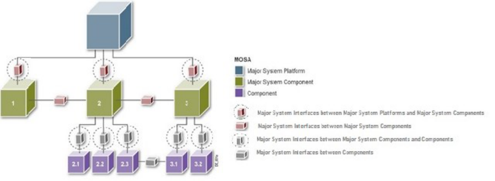
3 Engineering Guidance for the Acquisition Pathways
ENGINEERING OF DEFENSE SYSTEMS GUIDEBOOK
101
27BFigure 3-9. MOSA and Modular System Interfaces
Programs successfully implementing a MOSA strategy will benefit from the identification of
required technical data and software deliverables necessary to field and maintain weapon
systems and their logistics support. The Acquisition Strategy should be updated throughout the
system’s life cycle to reflect changes in the MOSA approach resulting from technology and
software evolutionary developments. In accordance with DoDI 5000.85, Section 3C.3.a.(5) for a
MDAP that uses a MOSA, the program’s Acquisition Strategy should:
Describe the modular open system approach to be used for the program;
Differentiate between the major system platform and major system components being
developed under the program, as well as major system components developed outside the
program that will be integrated into the MDAP;
Describe the evolution of major system components that are anticipated to be added,
removed, or replaced in subsequent increments;
Identify additional major system components that may be added later in the life cycle of
the major system platform;
Describe how intellectual property and related issues, such as technical data deliverables,
that are necessary to support a modular open system approach, will be addressed; and
Describe the approach to systems integration and systems-level configuration
management to ensure the system can operate in the applicable cyber threat environment.
The SEP is also updated to reflect the MOSA-related updates and modifications employed
throughout the system and its system elements.
Specific MOSA-related data deliverables that should be considered include:
Open Systems Management Plan (DI-MGMT-82099)
Software Development Plans (DI-IPSC-81427)
3 Engineering Guidance for the Acquisition Pathways
ENGINEERING OF DEFENSE SYSTEMS GUIDEBOOK
102
Software Development Status Reports (DI-MCCR-80459)
Software Development Summary Reports (DI-AVCS-80902)
Software Design Descriptions (DI-IPSC-81435)
Hardware development plans and Hardware Design Descriptions
In addition, the PM should maintain an open systems management plan. The plan describes the
offeror’s approach for:
OSA, modularity and open design
Inter-system element dependencies
Design information documentation
Technology insertion
Life cycle sustainability
Interface design and management
Treatment of proprietary or vendor-unique elements
Reuse of preexisting items, including all COTS/NDI system elements, their functionality
and proposed function in the system
Copies of license agreements related to the use of COTS/NDI system elements for
Government approval
The open system management plan should also include a statement explaining why each
COTS/NDI system element was selected for use.
Program products typically used in making decisions regarding MOSA include:
System Requirements
Acquisition Strategy
PPP
SEP
AoA
Enterprise Architecture
Modular open systems approaches and requirements should be addressed at design reviews, e.g.,
SRR, PDR, and CDR.
3 Engineering Guidance for the Acquisition Pathways
ENGINEERING OF DEFENSE SYSTEMS GUIDEBOOK
103
See DoDM 5010.12-M for data deliverables, and DoDM 4120.24 for DoD procedures pertaining
to development and distribution of defense specifications and standards, e.g., MOSA-enabling
standards, DIDs. PMs and systems engineers should use ASSIST, formerly known as
Acquisition Streamlining and Standardization Information System, to gain access to data item
deliverables (e.g., DIDs), MOSA-enabling standards, and other defense standardization
documents (e.g., MIL-STD-188, MIL-STD-1472, STANAG-5616) that may be appropriate for
each specific program.
3.2.5 49BDigital Engineering
The DoD Digital Engineering Strategy (https://ac.cto.mil/wp-content/uploads/2019/06/2018-
Digital-Engineering-Strategy_Approved_PrintVersion.pdf) defines digital engineering as an
“integrated digital approach using authoritative sources of system data and models as a
continuum across disciplines to support life cycle activities from concept through disposal.”
Digital engineering updates traditional systems engineering practices to take advantage of
computational technology, modeling, analytics, and data sciences. As evidenced across the
Services and industry, digital engineering is a necessary practice to support acquisition in an
environment of increasing global challenges and dynamic threat environments. As such,
programs are highly encouraged to implement digital engineering.
Benefits of Digital Engineering
The overall vision of DoD digital engineering is to “modernize how the Department designs,
develop, delivers, operates, and sustains systems” (The DoD Digital Engineering Strategy
(https://ac.cto.mil/wp-content/uploads/2019/06/2018-Digital-Engineering-
Strategy_Approved_PrintVersion.pdf)). The expected benefits of adopting a digital engineering
approach to system design/development are:
Informed decision making and greater insight through increased transparency
Enhanced communication
Increased understanding for greater flexibility and adaptability in design
Increased confidence that the capability will perform as expected
Increased efficiency in engineering and acquisition practices
Project/Program Office Digital Engineering Roles, Responsibilities, and Activities
The extent to which a project or program office will need to embrace digital engineering will
depend on multiple factors including but not limited to the following:
Where the development is in its life cycle
What previous investments were made in digital engineering during prior stages of the
life cycle
3 Engineering Guidance for the Acquisition Pathways
ENGINEERING OF DEFENSE SYSTEMS GUIDEBOOK
104
For an acquisition program, which of the adaptive acquisition framework pathways of the
new DoD 5000 acquisition policy and guidance this program falls under
The respective organization’s experience and lessons learned in implementing DE within
similar or adjacent projects/programs (e.g., organizationally adjacent; functionally
adjacent)
The remaining activities to be performed (e.g. design, testing, sustainment, retirement,
reuse, etc.,)
Considerations for Implementing Digital Engineering
Models and simulations are integral to digital engineering as they capture data and help the PM
make informed, data-driven decisions throughout a project’s life cycle. The goals of the DoD
Digital Engineering Strategy are to “promote the use of digital representations and components
and the use of digital artifacts as a technical means of communication across a diverse set of
stakeholders.” As such, activities embracing digital engineering depend upon a well-defined plan
for what models and simulations are needed at various way points along the life cycle. The
opposite is not true, however. A project does not need to fully embrace a digital engineering
approach to be able to make good use of models and simulations throughout its life cycle.
Digital Threads
The digital thread is a term for the lowest level design and specification for a digital
representation of a physical item. The digital thread is a critical capability in model-based
systems engineering (MBSE) and the foundation for a digital twin. The digital thread refers to
the communication framework that allows a connected data flow and integrated view of the
asset’s data throughout its life cycle across traditionally siloed functional perspectives.
Digital Twins
A digital twin is a virtual representation that serves as the real-time digital counterpart of a
physical object or system that spans its life cycle, is updated from real-time data, and uses
simulation, machine learning, and reasoning to help decision making. The object could be a
missile system, a building, a ship, a sensor, or a jet engine. Connected sensors on the physical
asset collect data that can be mapped onto the virtual model. Anyone looking at the digital twin
can review crucial information about how the physical thing is performing.
Digital twins of a system or a component can be a means to overcome the significant
development, testing, and validation challenges and timelines needed to support quicker fielding
of new verified capabilities. Digital twins are possible because of “Internet of Things” sensors
that gather data from the physical world and send it to be virtually reconstructed. These include
design and engineering details that describe the asset’s geometry, materials, components, and
behavior, or performance. When combined with analytics, data from a digital twin data can
unlock hidden value for an organization and provide insights about how to improve operations,
increase efficiency, or discover and resolve problems before the real-world asset is affected.
3 Engineering Guidance for the Acquisition Pathways
ENGINEERING OF DEFENSE SYSTEMS GUIDEBOOK
105
3.2.6 50BSystem Security Engineering
System Security Engineering (SSE) integrates disciplines such as anti-tamper (AT), Defense
Exportability Features (DEF), hardware assurance, software assurance, and supply chain risk
management. The desired outcome is a comprehensive program and system protection within the
constraints of cost, schedule, and performance while maintaining an acceptable level of risk. The
system security engineer leads the evaluation and balancing of security contributions to produce
a coherent security approach. Additional information is provided in the T&PP Guidebook
(forthcoming) for the MCA pathway.
3.2.7 51BTechnical Reviews and Assessments
In accordance with DoDI 5000.88, PMs will conduct technical reviews and audits of program
progress for systems in development as a basis for transitioning between phases within the
development plan of work. Reviews should be event-driven and based on entrance criteria as
documented in the SEP. Section 3 of the SE Guidebook covers technical reviews, but selective
information is amplified in the following sections.
3.2.7.1 Independent Review Teams
As a best practice fundamental to engineering and risk management, a program should allow
periodic reviews by independent technical personnel. The CAE will implement a technical
review process, in accordance with DoDI 5000.88. Ideally, the Independent Review Team (IRT)
remains consistent throughout the program life cycle and serves as a trusted technical adviser to
the CAE. The IRT identifies and documents critical issues that jeopardize achieving safety and
security thresholds, and program and mission objectives. The team recommends corrective
actions and risk mitigation activities necessary to reduce risk. Results are provided directly to the
CAE, with coordination but not undue influence from the PMO. The PM, with support from the
Systems Engineer, will review, develop, and implement corrective action to the satisfaction of
the CAE. The CAE should approve team members to ensure all organizational, professional, and
relational influences from the program management office are avoided.
3.2.7.2 Independent Technical Risk Assessment
In accordance with 10 U.S.C. 2448, all MDAPs will undergo an ITRA before Milestone A and B
approval and before any decision to enter into LRIP or FRP. Although only MDAPs are required
to undergo the ITRA, as a best practice all acquisition programs should conduct independent risk
assessments throughout the life of the program. ITRAs provide a means to independently assess
a program’s technical risk at key points. ITRAs should be conducted in accordance with DoDI
5000.88, sec 3.5.b., the DoD ITRA Execution Guidance, and the DoD ITRA Framework for Risk
Categorization. ITRAs consider the full spectrum of technology, engineering, and integration
risk. The organization conducting the ITRA designates a lead, who forms a team composed of
technical experts with in-depth domain knowledge of technical considerations associated with

3 Engineering Guidance for the Acquisition Pathways
ENGINEERING OF DEFENSE SYSTEMS GUIDEBOOK
106
the program under assessment. Team members should be independent from the program office
and the direct chain of command between the program office and Milestone Decision Authority.
3.2.7.3 Systems Engineering Technical Reviews
PMs should plan for and conduct technical review and audits to establish the technical baselines,
assess the system’s technical maturity, and review and assess technical risks. The SEP should
include design review planning. In accordance with DoDI 5000.88, Sec 3.5.a., unless waived
through the SEP approval process, the PM will conduct these system-level reviews, or equivalent:
System Requirements Review (SRR) or System Functional Review (SFR)
Preliminary Design Review (PDR)
Critical Design Review (CDR)
System Verification Review (SVR) or Functional Configuration Audit (FCA)
Production Readiness Review (PRR)
Physical Configuration Audit (PCA)
For all ACAT ID programs, the PM will invite representatives from the office of USD(R&E) to
participate in all design reviews.
Figure 3-10 provides the end-to-end perspective and the integration of SE technical reviews and
audits for the MCA pathway.
Figure 3-10. Technical Reviews and Audits for the Major Capability Acquisition Life Cycle
3 Engineering Guidance for the Acquisition Pathways
ENGINEERING OF DEFENSE SYSTEMS GUIDEBOOK
107
3.2.7.4 PDR and CDR Assessments
In accordance with Section 2366b of Title 10 U.S.C., programs will undergo a PDR assessment
before approval of Milestone B, unless the Milestone Decision Authority waives the assessment.
The Office of USD(R&E) conducts PDR assessments for ACAT ID programs. In addition,
OUSD(R&E) will conduct CDR assessment for ACAT ID programs. The results of these
assessments will be used to inform the Milestone Decision Authority of any technical risks,
maturation of the technical baseline, and the program’s readiness to proceed. For all other
MDAPs, the DoD Component concerned will conduct PDR and CDR assessments.
PDR Assessment - The PDR assesses the maturity of the preliminary design supported by
the results of requirements trades, prototyping, and critical technology demonstrations.
The PDR should establish the allocated baseline and confirm that the system under
review is ready to proceed into detailed design (development of build-to drawings,
software code-to documentation, and other fabrication documentation) with acceptable
risk. The PM should consider conducting the PDR before contract award for EMD. The
timing of the PDR relative to the Development RFP Release Decision Point is at the
discretion of the DoD Component. The Component should balance the need for more
mature design information to support source selection with the costs of either: extending
multiple sources’ design activities from the PDR until award of the full EMD contract or
having a gap in development before EMD award.
CDR assessment. The CDR assesses design maturity, design build-to or code-to
documentation, remaining risks, and is where the initial product baseline is established. It
should be used as the decision point that the system design is ready to begin
developmental prototype hardware fabrication or software coding with acceptable risk. In
accordance with DoDI 5000.88, a system-level CDR assessment will be conducted for
MDAPs. For ACAT ID programs, OUSD(R&E) will conduct the CDR assessment to
inform the Milestone Decision Authority of the program’s design maturity, technical
risks, and the program’s readiness to begin developmental prototype hardware fabrication
and/or software coding with acceptable risk. For ACAT IC and IB programs, the CAE
will conduct the CDR assessment.
3.2.7.5 Technology Readiness Assessment
A Technology Readiness Assessment (TRA) is a systematic, evidence-based process that
evaluates the maturity of technologies (hardware, software, and processes) critical to the
performance of a larger system or the fulfillment of the key objectives of an acquisition program.
Title 10 United States Code (U.S.C.) Section 2366b requires the Milestone Decision Authority
certify that the technology in an MDAP has been demonstrated in a relevant environment before
Milestone B approval. DoD assesses the maturity of program technologies and any associated
risks, by conducting TRAs.
3 Engineering Guidance for the Acquisition Pathways
ENGINEERING OF DEFENSE SYSTEMS GUIDEBOOK
108
For programs for which an ITRA is conducted, a TRA report is not required as the ITRA report
forms the basis for the U.S.C. 2366b certification. ITRA teams may leverage technology
maturation activities and receive access to results in order to perform independent technical
reviews and assessments.
In accordance with DoDI 5000.88, programs will assess and document the technology maturity
of all critical technologies consistent with the TRA guidance maintained by USD(R&E).
PMs of MDAPs should conduct knowledge-building TRAs throughout the DoD acquisition life
cycle, including at PDR, CDR, and Milestone C. These assessments should include the
reassessment of all elements of the system design to identify any new critical technology
elements and their associated technology readiness levels as a result of any system design
changes or new knowledge obtained during the engineering and manufacturing development
phase. See the DoD Technology Readiness Assessment (TRA) Guidance for additional
information.
3.3 38BMiddle Tier of Acquisition
The MTA pathway is intended to fill a gap in the DAS for those capabilities that have a level of
maturity to allow them to be rapidly prototyped within an acquisition program or fielded within 5
years of MTA program start. The MTA pathway may be used to accelerate capability maturation
before transitioning to another acquisition pathway or may be used to minimally develop a
capability before rapidly fielding.
3.3.1 52BRapid Prototyping
The rapid prototyping pathway provides for the use of innovative technologies to rapidly develop
fieldable prototypes to demonstrate new capabilities and meet emerging military needs. The
objective of an acquisition program under this pathway will be to field a prototype meeting
defined requirements that can be demonstrated in an operational environment and provide for a
residual operational capability within 5 years of the MTA program start date. Virtual prototyping
models are acceptable if they result in a fieldable residual operational capability. MTA programs
may not be planned to exceed 5 years to completion and, in execution, will not exceed 5 years
after MTA program start without a Defense Acquisition Executive waiver.
3.3.1.1 Systems Engineering
There are no mandated SE processes, technical reviews, or documents for the MTA pathway.
PMs and Systems Engineers should tailor and apply SE processes and practices to maximize the
benefit to rapid prototyping program objectives by considering the prioritization of the
requirements and priorities while also considering funding and other design considerations. Most
rapid prototyping programs exploit mature technologies, so integration and interoperability are
important considerations, and the programs require collaborative information and knowledge
sharing to succeed. SE processes should add value and not require excessive bureaucracy.
3 Engineering Guidance for the Acquisition Pathways
ENGINEERING OF DEFENSE SYSTEMS GUIDEBOOK
109
Systems Engineers should collaborate with the PM to decide where to include, truncate, or
eliminate non-mandatory SE processes. Systems Engineers should review other sections of this
guide for further recommendations.
Work is ongoing to accumulate an SE Body of Knowledge, best practices, and use cases. In the
interim, the following sources may be helpful to programs implementing SE in rapid capability
development and fielding: (1) Expedited Systems Engineering for Rapid Capability and Urgent
Needs A013 Final Technical Report SERC-2012-TR-034 (2012)) (2) INCOSE Systems
Engineering Body of Knowledge, www.sebokwiki.org.
3.3.1.2 Software Engineering
The term “prototype” has been defined in numerous ways in DoD, industry, and academic
literature. This section uses the following definition:
Prototype: a model (e.g. physical, digital, conceptual, and analytical) built to evaluate and
inform its feasibility or usefulness
As stated previously in this guidebook, software is often the basis of system complexity and
performance, providing functionality critical to battlefield dominance and maintaining
operational advantage in an environment of change. Software development and sustainment
frequently contribute a major portion of total system life-cycle cost, schedule, and risk. As
system complexity has increased, so too has the demand to provide new capabilities to the
warfighter at an ever quicker pace. To tackle these challenges, programs can reduce technical
risk by taking an approach to capability development that makes extensive use of prototyping
and experimentation:
Validating designs and feasibility of design concepts
Increasing warfighter/operational collaboration, early feedback, and learning (“shift left”
– see Section 3.2.2.3) from rapid iterative prototype demonstration
Exposing integration challenges early
Refining and validating performance requirements can be met
Providing insight into technology maturity
Verifying analytical and simulation models
Reducing uncertainty/unknowns
Identifying potential reliability and sustainability issues, and cost drivers
Compressing the feedback loop cycle time
These benefits not only reduce risk and generate real data to support critical decisions but also
increase responsiveness and flexibility to deliver timely solutions to warfighter needs.
3 Engineering Guidance for the Acquisition Pathways
ENGINEERING OF DEFENSE SYSTEMS GUIDEBOOK
110
The increased use of prototyping within and outside of DoD in recent years is partially
attributable to the tools and methods available today that enable the rapid building, testing,
rework, and retesting of prototypes in very short time cycles. To take full advantage of these
developments, the Department will need engineers with new competencies and skill sets (see
Section 3.5.2.1 Software Engineering Enablers, Activities, and Competencies).
System prototypes may be physical or math models and simulations that emulate expected
performance. High-risk concepts may require scaled models to reduce uncertainty too difficult to
resolve purely by mathematical emulation. Programs should demonstrate software prototypes
that reflect the results of key trade-off analyses to generate real representative data. The data
from these demonstrations provide software performance (e.g., latency, security architecture,
integration of legacy services and scalability) and reference data to inform decisions as to the
concept maturity.
Programs often use competitive prototyping, usually involving two or more competing contractor
teams, to identify and mitigate technical risks. Programs may use prototyping in source selection
leading to formal acquisition contract award(s). DoD has used competitive prototyping for
programs such as aircraft, but use of competitive prototyping in software-intensive system
developments is a relatively recent occurrence.
Below are some software engineering considerations:
Solid System and Software Engineering habits provide the foundational basis to build on.
Staffing Size, Skill, and Experience promote success. Successfully managing a
prototyping effort, particularly a competitive effort, requires more staffing, skillsets, and
expertise than commonly expected. The program office team must have the resources and
knowledge to skillfully plan, monitor, manage, and evaluate the effort.
Cultivate Active Stakeholder Engagement. As with any Agile/DevSecOps effort, active
persistent collaboration among requirements and operational stakeholders and frequent
demonstrations and feedback loops will deliver better product results. Prototyping efforts,
including competitive efforts, must be designed to encourage active participation from
the end-users and other stakeholders throughout the life cycle. Frequent iterative
demonstrations of progress facilitate stakeholder involvement. Active engagement with
warfighter and operational users is crucial to understanding and satisfying requirements
and performance needs.
Technical Risk Reduction is the primary focus and goal of prototyping to eliminate or
burn down technical risk as much as possible. With this in mind, the program needs to
consider how these risks will be decomposed, the burn down planned, and how progress
to plan and performance will be monitored, managed, and tracked/measured.
Do not overlook “traditional downstream” Stakeholders. The eventual deliverable of this
effort and the different authorities that will be involved in this process, such as
3 Engineering Guidance for the Acquisition Pathways
ENGINEERING OF DEFENSE SYSTEMS GUIDEBOOK
111
certification and accreditation authorities, are often overlooked in prototyping efforts.
These stakeholders need to be identified and planned into the efforts early to ensure their
engagement throughout the life cycle (“shift left”).
Deliverables. Programs need to consider the deliverables necessary for the program to
support the competitive down-selection or to verify and validate whether program goals
and requirements have been met. What intellectual capital, data rights and core
competencies must be retained? Particularly, with competitive down-selection the
program should consider what contract vehicles can ensure that the losing competitors’
capital and experience can be retained if needed. This works to the programs interests,
and also that of the competitors.
Transition to Production/Field. Programs should thoroughly consider the prototype
suitability for fielding/production. This is particularly important with competitive
prototyping evaluations. What potential risks are there? How much effort will production
require? What weaknesses do the prototypes have, for instance architecture,
requirements, integration/maintainability or scalability?
Pathway Transition: Rapid Prototyping to Rapid Fielding
The MTA pathway authorizes a rapid fielding pathway (DoDI 5000.80 Sec 3.2) for prototypes
that meet the following criteria:
Proven technology to field production quantities of new or upgraded systems is utilized
with minimal development required.
The original prototyping project was successfully completed and demonstrated in a
relevant environment.
Production is expected to begin within six months and be completed within five years of
the development of an approved requirement.
Programs utilizing the Rapid Prototyping Acquisition pathway enables DoD Program Managers
to burn down technical risk early, inform requirements, mature technology for warfighter use,
ensure delivery of integrated and interoperable capability driving down costly technical risk and
discovery during procurement.
Work is ongoing to accumulate further software engineering considerations, best practices, and
lessons learned. Additions will be addressed in a future version of this guidebook.
3.3.1.3 Specialty Engineering
3.3.1.3.1 Reliability and Maintainability Engineering
R&M engineering activities should be tailored to meet the objectives of the MTA program.
Middle Tier Rapid Prototyping (MTRP) programs should consider approaches for capturing
reliability and maintainability performance. To identify MTRP program risk related to R&M, at
3 Engineering Guidance for the Acquisition Pathways
ENGINEERING OF DEFENSE SYSTEMS GUIDEBOOK
112
a minimum in demonstration, programs should plan for testing in relevant and operational
environments and ensure that design reviews identify and mitigate failure modes.
Guidance for the R&M engineering activities applicable to the MTA pathway is in development
and will be included as an Appendix to the R&M Engineering Management Body of Knowledge
(see DDR&E(AC)/Engineering website).
In the interim, the PM, Systems Engineer, and Lead Software Engineer should work to properly
align the applicable R&M Engineering activities needed to reduce program risk. Table 3-13
“R&M Activities by Acquisition Phase” should be used as a starting point to assess appropriate
activities needed to deliver capability that is reliable, maintainable, and supportable.
3.3.1.3.2 Manufacturing and Quality
M&Q personnel, working with the Program Manager, Systems Engineer, and other IPT
members, identify and manage manufacturing, quality, and producibility requirements and risks
throughout the Rapid Prototyping process. M&Q personnel should:
Support the development of program documentation to include acquisition strategies
o Systems Engineering Plan with planned M&Q management activities
Support the development and implementation of efficient and cost-effective M&Q
activities and processes
o Cost estimating (identify M&Q cost drivers)
o Cost tracking and improvement
Support demonstration and evaluation of prototype design, build, and test activities
o Identification, tracking, and management of technical risks
o Systems engineering technical reviews, to ensure M&Q considerations are addressed
early
The manufacturing of the prototype(s) to include proposed components, subsystems, and systems
should occur under the umbrella of M&Q best practices, thus any proposed contractors should be
operating under a documented M&Q management system consistent with industry best practices
such as those described in:
AS6500, Manufacturing Management Program
MIL-HDBK-896A, Manufacturing Management Program Guide
AS9001, Quality Management System, or
ISO 9001, Quality Management System
3 Engineering Guidance for the Acquisition Pathways
ENGINEERING OF DEFENSE SYSTEMS GUIDEBOOK
113
Prototyping contractors should have developed and provided to the government their M&Q Plans
for the proposed prototype system or subsystems. M&Q personnel should assess these plans for
completeness and adequacy.
In order to field a prototype system within 5 years, the technologies and manufacturing processes
used to implement these final system configurations must be significantly mature and assessed
using the appropriate TRL/MRL criteria based on acceptable program risk. Final risk
assessments should indicate that critical manufacturing processes and technologies are matured
sufficiently to support fielding. A tailored manufacturing readiness assessment and PRR is
recommended before entering production.
3.3.1.3.3 Human Systems Integration
Prototyping projects should take into account the manner in which those who will operate,
maintain, and support the technical system will interact with that system. HSI practitioners
should engage early due to the accelerated pace and the PM’s authority to use a “tailor in”
approach.
HSI Practitioner Engagement for Planning:
In MCA programs, HSI is a required element in the Acquisition Strategy and should be included
in an MTA pathway Acquisition Strategy. Cost estimates that include funding for HSI, such as
training and user testing, will increase the likelihood that the system will meet user needs.
HSI Practitioner Engagement for Development:
The MTA team contracts with industry or works with government organizations to design,
develop, and test prototypes based on the approved Acquisition Strategy.
HSI Practitioner Engagement for O&S:
Ensuring the system has a viable product support package is essential to the operators,
maintainers, and supporters of the system.
Regardless of whether the prototype transitions to another pathway or is returned to the technical
base, HSI practitioners need to document all HSI activities that the program accomplished as
well as those HSI activities that remain and to be accomplished for successful transition.
Requirements should include HSI considerations throughout the MTA pathway. The PM and
Systems Engineer should ensure the HSI SMEs participate during planning and the HSI SMEs
should advocate for HSI to become part of the MTA process.
If HSI practitioners have been successful in influencing activities in the planning phase, this
planning will help ensure the program implements HSI considerations during development. If the
contract with industry or the agreement with the government organization developing the
prototype specify that the program address HSI issues, then HSI practitioners can work with
industry and government counterparts to ensure the program continues to address HSI issues.
3 Engineering Guidance for the Acquisition Pathways
ENGINEERING OF DEFENSE SYSTEMS GUIDEBOOK
114
HSI practitioners should do their best to ensure personnel collect human performance data during
tests and demonstrations.
For a system to be viable and meet requirements in the prototype operations and sustainment
activity, it must be fielded with the necessary number of maintainers, proper training for those
maintainers, and the test equipment and tools needed to maintain the system.
3.3.1.3.4 System Safety Engineering
For MTRP programs, PMs and Systems Engineers should develop and implement a tailored
System Safety Program to ensure the program identifies and assesses potential hazards (hardware
and software), mitigating controls, and safety risks during prototyping tests, demonstrations, and
fielding. PMs and Systems Engineers should use the System Safety methodology in MIL-STD-
882 to manage System Safety and environmental and occupational health considerations as an
integral part of the program's overall SE process.
PMs and Systems Engineers should tailor System Safety risks and requirements to minimize the
injury to or loss of personnel and degradation of their equipment, and to reduce impact on the
environment. In accordance with MIL-STD-882, the program will eliminate hazards when
possible, or accept and manage the risks when it is not possible to eliminate them.
The program should use MIL-STD-882, Table 3-16 “System Safety Activities by Acquisition
Phase,” and the guidance provided in the DoD Joint Software Systems Safety Engineering
Handbook as a starting point to assess appropriate activities needed to deliver capability that
minimizes System Safety risks and the contribution of software to System Safety risks.
The program should use a closed-loop HTS to document, track, and maintain hardware and
software-related hazards and their associated risks data.
3.3.1.3.5 Parts Management
The PM should address and implement parts management and DMSMS management during
design reviews, parts selection, and parts redesign, where appropriate. During parts selection the
PM should avoid introducing obsolete parts into a system design. A program office’s DMSMS
management activities should assist its parts selection and parts redesign efforts.
Program offices should include a DMSMS management team that begins managing DMSMS
upon the initiation of the MTA program. DMSMS management should be considered part of
supportability during rapid prototyping and in the lead-up to production, during which period the
program office should focus its DMSMS management effort on assessing system designs for
DMSMS resilience. The DMSMS management team should prepare a DMSMS management
plan, including a risk-based approach to determine items to monitor for obsolescence.
Section 2.2.3.3. of the SD-22 contains more information on the tailoring of MCA DMSMS
management to the MTA pathway.
3 Engineering Guidance for the Acquisition Pathways
ENGINEERING OF DEFENSE SYSTEMS GUIDEBOOK
115
3.3.1.4 Modular Open Systems Approach
Implementing MOSA for the rapid development of technology provides greater flexibility to
insert new capabilities that provide a technological advantage to the warfighter. Moreover,
MOSA provides the ability to separate the development of higher risk prototype components and
subsystem technology maturation efforts from the major system platform development efforts.
MOSA is generally used to facilitate modularity in MDAP platforms in the traditional MCA
pathway by maturing advanced technologies. Using MOSA for MTA rapid development,
prototyping, and experimentation of weapon system components or other technologies, including
those based on commercial items and technologies, separate from acquisition programs of
record, enables innovation and encourages competition when employing a modular design and
open architecture, along with an open business model to facilitate incremental modular
development. In the MTA pathway, MOSA enables PMs to focus on developing more rapidly
evolving technologies internal to the system.
3.3.1.5 Digital Engineering
A digital engineering-based systems engineering approach is highly encouraged for all new
programs of record, enhancement efforts, and early engineering efforts such as prototyping. The
program’s Acquisition Strategy and SEP should describe the approach and implementation. The
extent to which an effort incorporates digital engineering practices to include a digital
environment depends on the requirements and desired end state of the effort. The program may
tailor the level of implementation. Refer to Section 3.2.5 for more information.
3.3.1.6 System Security Engineering
SSE integrates system security engineering disciplines such as anti-tamper, Defense
Exportability Features, hardware assurance, software assurance, and supply chain risk
management. The desired outcome is a comprehensive program and system protection within the
constraints of cost, schedule, and performance while maintaining an acceptable level of risk. The
system security engineer leads the evaluation and balancing of security contributions to produce
a coherent security. Additional information is provided in the T&PP Guidebook (forthcoming)
for the Middle Tier of Acquisition Rapid Prototyping pathway.
3.3.1.7 Technical Reviews and Assessments
3.3.1.7.1 Independent Review Teams
Periodic reviews conducted by independent technical personnel are a core best practice
fundamental to engineering development and managing risk. The CAE should implement a
technical review process, tailored for this acquisition pathway, to identify and document critical
issues that jeopardize achieving program safety and security thresholds, program and mission
objectives, and recommend the necessary corrective actions and risk mitigation activities
required to reduce risk. Results should be provided directly to the CAE, with coordination but
not undue influence from the PMO. The PM, with support from the Systems Engineer, will
3 Engineering Guidance for the Acquisition Pathways
ENGINEERING OF DEFENSE SYSTEMS GUIDEBOOK
116
review, develop, and implement corrective action to the satisfaction of the CAE. The CAE
should approve team members to ensure all organizational, professional, and relational
influences from the program management office are avoided.
3.3.1.7.2
Independent Technical Risk Assessment
There are generally three circumstances in which an ITRA must be conducted on a rapid
prototyping program:
When preparing to transition to the MCA pathway as an MDAP
As directed by the Secretary of Defense
As directed by the CAE or appropriate decision authority
In accordance with 10 U.S.C. 2448b, all MDAPs undergo an ITRA before Milestone A or B
approval, or before any decision to enter into LRIP or FRP. The PM and the office responsible
for conducting the ITRA should begin planning and coordinating the ITRA at least 12 months
before the planned MCA entry milestone. See Section 3.2.7.2 of the MCA pathway for more
details on conducting an ITRA to support milestone entry into the MCA pathway.
The Secretary of Defense may also direct an ITRA, in accordance with 10 U.S.C. 2448b. In
addition, as the decision authority, the CAE may direct an ITRA be conducted on a program.
These ITRAs are to advise the PM and decision authority on technical risk earlier in the program
and can be used to inform program objectives, Test Strategy, Acquisition Strategy, and other
program aspects. Often, the ITRA conducted for this purpose identifies risks not previously
considered by the PM’s risk management process, increasing the PM’s ability to proactively
mitigate risks to key program objectives.
3.3.1.7.3 Systems Engineering Technical Reviews
In accordance with DoDI 5000.80, paragraph 2.5.b, “PMs will ‘tailor- in’ reviews, assessments,
and relevant documentation that result in an Acquisition Strategy customized to the unique
characteristics and risks of their program. PMs will ensure operational, technical, and security
risks are identified and reduced so that fielded systems are capable, effective, and resilient.” In
addition, PMs regularly report on program status and technical maturity.
To accomplish these responsibilities, PMs should consider conducting the following technical
reviews and audits, or equivalent, to establish the technical baselines, assess the system’s
technical maturity, and review and assess technical risks:
System Requirements Review (SRR) or System Functional Review (SFR)
Preliminary Design Review (PDR)
Critical Design Review (CDR)
3 Engineering Guidance for the Acquisition Pathways
ENGINEERING OF DEFENSE SYSTEMS GUIDEBOOK
117
System Verification Review (SVR) or Functional Configuration Audit (FCA)
Production Readiness Review (PRR)
Physical Configuration Audit (PCA)
The PM should “tailor-in” the technical reviews applicable to the program’s Acquisition
Strategy, development and fielding activities, and overall level of technical maturity. The PM
should consider where the MTA program is entering the pathway and where it is planned to
transition. Tailoring-in of technical reviews should also be informed by the program’s technical
risks.
See Section 3.2.7.3 of the MCA pathway and Section 3 of the SE Guidebook for more details on
each technical review.
3.3.1.7.4 PDR and CDR Assessments
PDR and CDR assessments are not required for MTA programs; however, a follow-on MCA
program entering at Milestone B will require a PDR assessment in accordance with Section
2366b of Title 10, U.S.C., unless waived by the Milestone Decision Authority. MTRP programs
that plan to transition to an MDAP at Milestone B should consider conducting a PDR and
providing the PDR assessment to support the milestone at transition.
Likewise, MTRP and Middle Tier Rapid Fielding (MTRF) programs with complex requirements,
a high degree of schedule concurrency, or integration of multiple maturing technologies should
consider a CDR assessment to ensure a strong technical baseline and identify risks that could
delay fielding the capability.
See Section 3.2.7.4 of the MCA pathway for more details on PDR and CDR assessments.
3.3.1.7.5 Technology Readiness Assessment
A TRA is a systematic, evidence-based process that evaluates the maturity of technologies
(hardware, software, and processes) critical to the performance of a larger system or the
fulfillment of the key objectives of an acquisition program. DoD assesses the maturity of
program technologies and any associated risks, by conducting TRAs.
For MTA programs, the PM should assess and document the technology maturity of all critical
technologies consistent with the TRA guidance maintained by USD(R&E). The maturity of critical
technologies should inform the Test Strategy and Acquisition Strategy, with the goal for MTRPs to
mature critical technologies and demonstrate a residual operational capability. The PM should
regularly assess and report the maturity of critical technologies.
For an MTA program transitioning to an MDAP, Title 10 United States Code (U.S.C.) Section
2366b requires that the Milestone Decision Authority certify that the technology has been
demonstrated in a relevant environment before Milestone B approval. PMs of MDAPs should
3 Engineering Guidance for the Acquisition Pathways
ENGINEERING OF DEFENSE SYSTEMS GUIDEBOOK
118
conduct knowledge-building TRAs throughout the DoD acquisition life cycle, including at PDR,
CDR, and Milestone C. These assessments should include the reassessment of all elements of the
system design to identify any new critical technology elements and their associated technology
readiness levels as a result of any system design changes or new knowledge obtained during the
engineering and manufacturing development phase. See the DoD Technology Readiness
Assessment (TRA) Guidance for additional information.
3.3.2 53BRapid Fielding
The Rapid Fielding pathway provides for the use of proven technologies to field production
quantities of new or upgraded systems with minimal development required. The objective of an
acquisition program under this path is to begin production within 6 months and complete fielding
within 5 years of the MTA program start date. The MTA program production start date is not to
exceed 6 months after MTA program start date without Defense Acquisition Executive waiver.
MTA programs may not be planned to exceed 5 years to completion and, in execution, will not
exceed 5 years after MTA program start without Defense Acquisition Executive waiver.
Rapid fielding is detailed in DoDI 5000.80, Operation of the Middle Tier of Acquisition,
paragraph 3.2 Rapid Fielding. The MTA instructions discussed, Operational Needs,
Demonstrating and Evaluating Performance, Acquisition and Funding Strategies, Life Cycle
Cost, Logistics Support, and Interoperability, Reducing Total Ownership Cost and Transitioning
Rapid Fielding Programs.
3.3.2.1 Systems Engineering
There are no mandated SE processes, technical reviews, or documents for this pathway. Because
of the streamlined nature of this pathway the SE activities focus primarily on support to the PM
for entrance criteria, requirements management, and other SE-related documentation as
applicable such as the Acquisition Strategy. Additional information regarding Rapid Fielding is
available at the DAU website: https://aaf.dau.edu/aaf/mta/fielding/planning/. Section 3.2.1.
includes related information and lessons learned. Systems Engineers should review the specialty
engineering sections of this guidebook for further recommendations on implementing SE in these
areas in each pathway.
3.3.2.2 Software Engineering
The focus of the MTA Rapid Fielding acquisition pathway is to provide a path for proven
technologies to field production quantities of new or upgraded systems with minimal
development effort and to begin production within 6 months of the start date. MTA may not be a
principal pathway for software development and engineering efforts. Instead programs will most
likely transition software from another pathway to MTA to field matured and completed
software efforts, as described in the Section 3.3.1.2 Software Engineering – Pathway Transition:
Rapid Prototyping to Rapid Fielding. As any relevant Software Engineering lessons learned and
best practices for this pathway are accumulated they will be reflected in this guidebook.
3 Engineering Guidance for the Acquisition Pathways
ENGINEERING OF DEFENSE SYSTEMS GUIDEBOOK
119
3.3.2.3 Specialty Engineering
3.3.2.3.1 Reliability and Maintainability Engineering
R&M engineering activities should meet the objectives of the MTA program. To identify MTRF
program risk related to R&M, at a minimum, programs should plan for testing in relevant and
operational environments and ensure that design reviews identify and mitigate failure modes.
Guidance for the R&M engineering activities applicable to the MTA pathway is in development
and will be included as an Appendix to the R&M Engineering Management Body of Knowledge
(see DDR&E(AC)/Engineering website).
In the interim, the PM, Systems Engineer, and Lead Software Engineer should work to properly
align the applicable R&M Engineering activities needed to reduce program risk. Table 3-13
“R&M Activities by Acquisition Phase” should be used as a starting point to assess appropriate
activities needed to deliver capability that is reliable, maintainable, and supportable.
3.3.2.3.2 Manufacturing and Quality
M&Q personnel, working with the Program Manager, Lead Systems Engineer, and other IPT
members, will ensure that manufacturing, quality, and producibility requirements and risks are
identified and managed throughout the Rapid Fielding process. Manufacturing and QA personnel
should:
Support the development of program documentation to include acquisition strategies
o Systems Engineering Plan with planned M&Q management activities.
Support the development and implementation of efficient and cost-effective M&Q
activities and processes
o Cost estimating (identify M&Q cost drivers)
o Cost tracking and improvement
Support demonstration and evaluation of prototype design, build, and test activities
o Support the identification, tracking, and management of technical risks
o Support all system engineering technical reviews, to ensure M&Q considerations are
addressed early
Manufacturing of the proposed rapid fielding system to include proposed components,
subsystems and systems should occur under the umbrella of M&Q best practices. Any proposed
contractors should be operating under a documented M&Q management system such as:
AS6500, Manufacturing Management Program
MIL-HDBK-896A, Manufacturing Management Program Guide
3 Engineering Guidance for the Acquisition Pathways
ENGINEERING OF DEFENSE SYSTEMS GUIDEBOOK
120
AS9001, Quality Management System, or
ISO 9001, Quality Management System
Contractors involved in the Rapid Fielding efforts should have developed and provided to the
government their M&Q Plans for the proposed system or subsystems. These plans should be
assessed for completeness and adequacy.
In order to field a system within five (5) years the technologies and manufacturing processes
used to implement these final system configurations must be significantly mature and assessed at
a high TRL/MRL based on acceptable risk. A tailored manufacturing readiness assessment and
PRR are recommended before entering production.
3.3.2.3.3 Human Systems Integration
During the planning phase of the Rapid Fielding pathway, the Systems Engineer should elicit
HSI SME support to have increased visibility and involvement for developing human
performance characteristics within the requirements and Acquisition Strategy. HSI practitioners
should be heavily involved in ensuring the human performance requirements and the selection
process to address HSI issues are adequately covered when COTS or GOTS are fielded.
3.3.2.3.4 System Safety Engineering
For MTRF programs, PMs and Systems Engineers should develop and implement a tailored
System Safety Program appropriately to align with the MTA and Rapid Fielding acquisition
approach to ensure the identification and assessment of potential hazards (hardware and
software), mitigating controls and safety risks during Rapid Prototyping test, demonstrations and
fielding. The System Safety methodology in MIL-STD-882 should be used to manage System
Safety, environmental and occupational health considerations as an integral part of the program's
overall SE process.
System Safety risks and requirements should be tailored and managed to minimize the injury to
or loss of Service members and degradation of their equipment, and to reduce impact on the
environment. In accordance with MIL-STD-882, the PM will eliminate hazards when possible,
and accepted and managed when not.
In addition to MIL-STD-882, Table 3-16 “System Safety Activities by Acquisition Phase,” and
the guidance provided in the DoD Joint Software Systems Safety Engineering Handbook, should
be used as a starting point to assess appropriate activities needed to deliver capability that
minimizes System Safety risks and the contribution of software to System Safety risks.
3.3.2.3.5 Parts Management
Parts management and DMSMS management should be addressed during design reviews and
implemented during parts selection and parts redesign, where appropriate. Parts selection should
3 Engineering Guidance for the Acquisition Pathways
ENGINEERING OF DEFENSE SYSTEMS GUIDEBOOK
121
continue to avoid the introduction of obsolete parts into the system design. A program office’s
DMSMS management activities can assist its parts management efforts.
Since COTS assemblies are particularly prone to become obsolete within the more than 4 years
of production of an MTA program, product roadmapping for supportability should be considered
mandatory. DMSMS management activities should inform product roadmapping for
supportability during production and operations. During this time, the program office should
seek to identify obsolescence issues as early as possible and put in place resolutions before
obsolescence issues impact the system.
Section 2.2.3.3. of the SD-22 contains more information on the tailoring of MCA DMSMS
management to the MTA pathway.
3.3.2.4 Modular Open Systems Approach
Implementing MOSA for the rapid fielding of proven technologies in new or upgraded systems
is beneficial when there is minimal development required. MOSA facilitates the development of
modularly upgradable systems with flexible architectures, where designs can be competitively
reconfigured, or technologically refreshed to respond to evolving or unstable conditions in the
environment in which the system operates. Adopting a modular technical design and an open
system approach enables competition, platform independence, and reduces vendor lock.
Additionally, hardware and software interfaces should use widely supported consensus-based
standards that are appropriately defined and disclosed. This implementation of MOSA can
provide operational flexibility to meet rapidly changing operational requirements and address
emerging commercial technology, maturing technology from government labs, technology from
defense prime research and development efforts, and technology from small business innovation
research solutions. Additionally, employing modular open system architectures that include
modular systems, standardized modular system interfaces and open specifications affords
systems technical flexibility to field incremental updates and deploy new capabilities to the
warfighter.
3.3.2.5 Digital Engineering
A digital engineering-based SE approach is highly encouraged for all new programs of record,
enhancement efforts, and early engineering efforts such as prototyping. The program’s
Acquisition Strategy and SEP should describe the approach and implementation. The extent to
which a rapid fielding effort incorporates digital engineering practices to include a digital
environment depends on the engineering heritage of the technologies that are being accelerated
into production and the end-state requirements for future engineering and sustainment. A
program may tailor the level of implementation. See Section 3.2.5 for more information.
3 Engineering Guidance for the Acquisition Pathways
ENGINEERING OF DEFENSE SYSTEMS GUIDEBOOK
122
3.3.2.6 System Security Engineering
SSE integrates system security engineering disciplines such as anti-tamper, Defense
Exportability Features, hardware assurance, software assurance, and supply chain risk
management. The desired outcome is a comprehensive program and system protection within the
constraints of cost, schedule, and performance while maintaining an acceptable level of risk. The
system security engineer leads the evaluation and balancing of security contributions to produce
a coherent security. Additional information is provided in the T&PP Guidebook (forthcoming)
for the MTA Rapid Fielding pathway.
3.3.2.7 Technical Reviews and Assessments
3.3.2.7.1 Independent Review Teams
Periodic reviews conducted by independent technical personnel are a core best practice
fundamental to engineering development and managing risk. The CAE should implement a
technical review process, tailored for this acquisition pathway, to identify and document critical
issues that jeopardize achieving safety and security thresholds, program and mission objectives,
and recommend the necessary corrective actions and risk mitigation activities required to reduce
risk. Results should be provided directly to the CAE, with coordination but not undue influence
from the PMO. The PM, with support from the Lead Engineer, will review, develop, and
implement corrective action to the satisfaction of the CAE. The CAE should approve team
members to ensure all organizational, professional, and relational influences from the program
management office are avoided.
3.3.2.7.2 Independent Technical Risk Assessment
There are generally three circumstances when an ITRA must be conducted on a rapid fielding
program:
When preparing to transition to the MCA pathway as an MDAP
If directed by the Secretary of Defense
If directed by the CAE or appropriate decision authority
In accordance with 10 U.S.C. 2448b, an ITRA will be conducted on all MDAPs before
Milestone A or B approval, or any decision to enter into low-rate or full-rate production. The PM
and the office responsible for conducting the ITRA should begin planning and coordinating the
ITRA at least 12 months before the planned MCA entry milestone. See Section 3.2.7.2 of the
MCA pathway for more details on conducting an ITRA to support milestone entry into the
MCA pathway.
The Secretary of Defense may also direct an ITRA, in accordance with 10 U.S.C. 2448b. In
addition, as the decision authority, the CAE may direct an ITRA be conducted on a program.
These ITRAs are to advise the PM and decision authority on technical risk earlier in the
3 Engineering Guidance for the Acquisition Pathways
ENGINEERING OF DEFENSE SYSTEMS GUIDEBOOK
123
program, and can be used to inform program objectives, Test Strategy, Acquisition Strategy and
other program aspects. Often, the ITRA conducted for this purpose identifies risks not previously
considered by the PM’s risk management process, increasing the PM’s ability to proactively
mitigate risks to key program objectives.
3.3.2.7.3 Systems Engineering Technical Reviews
Program Managers should consider conducting the following technical reviews and audits to
establish the technical baselines, assess the system’s technical maturity, and review and assess
technical risks:
System Requirements Review (SRR) or System Functional Review (SFR).
Preliminary Design Review (PDR).
Critical Design Review (CDR).
System Verification Review (SVR) or Functional Configuration Audit (FCA).
Production Readiness Review (PRR).
Physical Configuration Audit (PCA).
In general, MTRF programs are more likely to benefit from a CDR, system verification review,
production readiness review and physical configuration audit. These reviews are especially
appropriate for a Rapid Fielding MTA program that ultimately plans to enter sustained
production through the MCA pathway.
See Section 3.2.7.3 of the MCA pathway and Section 3 of the SE Guidebook for more details on
the specific technical reviews.
3.3.2.7.4 PDR and CDR Assessments
PDR and CDR assessments are not required or recommended for MTA – Rapid Fielding
programs.
3.3.2.7.5 Technology Readiness Assessment
A TRA is a systematic, evidence-based process that is used to evaluate the maturity of
technologies (hardware, software, and processes) critical to the performance of a larger system or
the fulfillment of the key objectives of an acquisition program. DoD assesses the maturity of
program technologies, and any associated risks, by conducting TRAs.
For MTA programs, the PM will assess and document the technology maturity of all critical
technologies consistent with the TRA guidance maintained by USD(R&E). The maturity of critical
technologies should inform the Test Strategy and Acquisition Strategy, with the goal for MTRPs to
mature critical technologies and demonstrate a residual operational capability. The PM should
regularly assess and report the maturity of critical technologies.
3 Engineering Guidance for the Acquisition Pathways
ENGINEERING OF DEFENSE SYSTEMS GUIDEBOOK
124
For an MTA program transitioning to an MDAP, Title 10 United States Code (U.S.C.) Section
2366b requires that the Milestone Decision Authority certify that the technology has been
demonstrated in a relevant environment before Milestone B approval. PMs of MDAPs should
conduct knowledge-building TRAs throughout the DoD acquisition life cycle, including at PDR,
CDR, and Milestone C. These assessments should include the reassessment of all elements of the
system design to identify any new critical technology elements and their associated technology
readiness levels as a result of any system design changes or new knowledge obtained during the
engineering and manufacturing development phase. See the DoD Technology Readiness
Assessment (TRA) Guidance for additional information.
3.4 39BUrgent Capability Acquisition
The purpose of the UCA pathway is to field capabilities to fulfill urgent existing or emerging
operational needs or quick reactions in less than 2 years.
3.4.1 54BSystems Engineering
There are no mandated SE processes, technical reviews, or documents for this pathway. Since
these products are usually NDI or near-NDI products, the primary SE considerations are to
ensure the capability is safe and secure, and meets warfighter needs and national security need.
The Systems Engineer can support the PM throughout the process as needed to achieve the
program goals and objectives which generally includes requirements validation and decision
analysis support. Additional information on the acquisition of urgent capabilities can be found at
the DAU website: https://aaf.dau.edu/aaf/uca/. Also there be may information and lessons
learned that programs can adapt from traditional SE processes as discussed Section 3.2.1.
Systems engineers should also review the individual specialty engineering sections of this
guidebook for further recommendations on how these areas should be implemented for each
pathway.
3.4.2 55BSoftware Engineering
For the UCA pathway and operational urgency, programs will aggressively streamline the
normal acquisition processes. The goal is to plan for the capability in a few weeks with
development and production measured in months. This should not be seen as a license to
abandon sound systems and software engineering practices, as anything fielded or delivered will
have to be sustained and must support the potential for rapid updates.
A typical use case for this pathway would be the need to respond to a new threat that puts our
warfighters or nation at risk. Rapidly responding requires an agile acquisition system and active
stakeholder collaboration to succeed under these constraints. Such projects lend themselves to a
DevSecOps methodology, which emphasizes software development and deployment speed to
intertwine development, security, and operations to achieve rapid value.
3 Engineering Guidance for the Acquisition Pathways
ENGINEERING OF DEFENSE SYSTEMS GUIDEBOOK
125
Given the compressed schedule timelines of the Urgent Capability Acquisition pathway, it is
critical to quickly assemble a cross-functional team that ensures warfighter or operational user
representation. Small, highly collaborative cross-functional teams with their short
communication and quick decision pathways foster agility and have produced the best results.
Programs should employ a highly iterative approach that quickly demonstrates small progressive
updates and provides hands-on stakeholder participation so as to reduce rework and help focus
the minimum viable product (MVP) solution.
Programs should evaluate any potential capability solutions or partial capability solutions
available internally within the DoD and Services and externally within industry or commercial
sectors. Programs supporting fielded systems that have established these connections and
regularly exercise rapid or accelerated delivery pathways will be in the best position to use the
Urgent Capability Acquisition pathway. Programs should use enterprise platforms and services
to the maximum extent possible, as opposed to independently developing a Software Factory or
DevSecOps pipeline. Programs can tailor established enterprise offerings (e.g., Platform One,
Black Pearl, Army Code Repositories and Transformation Environment (CReATE)) to specific
needs, saving time and effort compared with developing a new product or method. For more
information on the Software Factory refer the R&E Software Engineering Guide (forthcoming).
3.4.3 56BSpecialty Engineering
3.4.3.1 Reliability and Maintainability Engineering
R&M engineering activities should meet the objectives of the UCA program. To identify UCA
program risk related to R&M, at a minimum, programs should plan for testing in relevant and
operational environments and ensure that design reviews identify and mitigate failure modes.
Guidance for the R&M engineering activities applicable to the UCA pathway is in development
and will be included as an Appendix to the R&M Engineering Management Body of Knowledge
(see DDR&E(AC)/Engineering website).
In the interim, the PM, Systems Engineer, and Lead Software Engineer should work to properly
align the applicable R&M Engineering activities needed to reduce program risk. Table 3-13
“R&M Activities by Acquisition Phase” should be used as a starting point to assess appropriate
activities needed to deliver capability that is reliable, maintainable, and supportable.
3.4.3.2 Manufacturing and Quality
M&Q personnel, working with the PM, Lead Systems Engineer, and other IPT members, should
ensure that manufacturing, quality, and producibility requirements and risks are identified and
managed throughout the process of fielding an urgent capability. Manufacturing and QA
personnel should:
Support a review of “Courses of Action” for M&Q implications and risks.
3 Engineering Guidance for the Acquisition Pathways
ENGINEERING OF DEFENSE SYSTEMS GUIDEBOOK
126
Support the development of program documentation to include acquisition strategies.
o SEP with planned M&Q management activities
Support the development and implementation of efficient and cost-effective M&Q
activities and processes.
o Cost estimating (identify M&Q cost drivers)
o Cost tracking and improvement
Support demonstration and evaluation of prototype design, build, and test activities.
o Identification, tracking, and management of technical risks
o Systems engineering technical reviews, to ensure M&Q considerations are addressed
early
Given the urgent need, the M&Q efforts should be tailored to address the identified risk. Since
the nature of the urgent capability program implies that a capability can be fielded on an
accelerated timeline, M&Q personnel should use existing documentation and manufacturing
plans, when possible.
The manufacturing of the proposed urgent capability including proposed components,
subsystems, and systems should occur under the umbrella of M&Q best practices. Any proposed
contractors should be operating under a documented M&Q management system such as:
AS6500, Manufacturing Management Program
MIL-HDBK-896A, Manufacturing Management Program Guide
AS9001, Quality Management System, or
ISO 9001, Quality Management System
Contractors should have developed and provided to the government their M&Q Plans for the
proposed system or subsystems as early as possible. These plans should be assessed for
completeness and adequacy.
To field an urgent capability within 2 years, the technologies and manufacturing processes used
to implement these final system configurations must be significantly mature and assessed using
the appropriate TRL/MRL criteria based on acceptable program risk. The program should
undergo a tailored manufacturing readiness assessment and PRR before entering production.
3.4.3.3 Human Systems Integration
Successful HSI in the UCA requires: highly experienced HSI practitioner SMEs, full-time
presence by the HSI SME to support the Systems Engineer, interpersonal skills as a “team
player,” excellent negotiating skills, and access to a responsive support network.
3 Engineering Guidance for the Acquisition Pathways
ENGINEERING OF DEFENSE SYSTEMS GUIDEBOOK
127
Pre-Development HSI practitioner engagement includes the following:
Obtain and study the Urgent Operational Needs that initiates the UCA process
Join the requirements analysis and requirements review processes
Participate in the course of action analysis and advocate for the choices that capitalize
most on the HSI considerations
Contribute to the Acquisition Strategy and the program baseline
Identify HSI risks, issues, and opportunities that need to be tracked through the remainder
of the pathway
Development HSI practitioner engagement includes the following:
Track the HSI issues identified during Pre-Development
Assess training materials
Review the Acquisition Strategy and program baseline
Contribute to the testing strategy
Participate in performance, safety, suitability, supportability, and training assessments
Call out deficiencies and safety issues deemed not acceptable to the Systems Engineer
P&D HSI practitioner engagement includes the following:
Contribute to milestone decision reviews (train maintenance and operating personnel)
Ensure organization acquiring the capability provides required training
Identify and communicate known hazards and accepted mishap risks
Verify necessary facilities, maintenance, and support equipment are provided
Track and resolve HSI issues as needed
O&S HSI practitioner engagement includes the following:
Collect data on the fielded system’s operators, maintainers, and supporters
Provide feedback and advocate for any proposed urgent improvements
Participate in operational test activities, if possible
Assist in the disposition analysis
Collaborate with other program office team members to share HSI information and data
Inform the disposition official of relevant HSI issues or concerns
3 Engineering Guidance for the Acquisition Pathways
ENGINEERING OF DEFENSE SYSTEMS GUIDEBOOK
128
3.4.3.4 System Safety Engineering
The PM and Systems Engineer should develop and implement a tailored System Safety Program
to align with the Urgent Capability Acquisition approach to ensure they identify and assess
potential hardware and software hazards, mitigating controls, and safety risks during Rapid
Prototyping test, demonstrations, and fielding. DoD programs use the System Safety
methodology in MIL-STD-882 to manage System Safety, environmental, and occupational
health considerations as an integral part of the program's overall SE process.
The PM and Systems Engineer tailor and manage System Safety risks and requirements to
minimize the injury to or loss of Service members and degradation of equipment, and to reduce
impact on the environment. In accordance with MIL-STD-882, hazards will be eliminated when
possible, and accepted and managed by the PM when not.
In addition to MIL-STD-822, programs should use the guidance in the DoD Joint Software
Systems Safety Engineering Handbook to assess and the contributions of Software to system-
level hazards.
The PM and Systems Engineer should use a closed-loop HTS to document, track, and maintain
hardware and software related hazards and their associated risk data.
3.4.3.5 Parts Management
In the UCA pathway the purpose of pre-development is to assess and select a course(s) of action
to field a quick-reaction capability and develop an acquisition approach. Once the acquisition
approach is identified, the PM should implement parts management for parts or systems, as
required, such as parts that require modification or if the UCA system enters longer term
sustainment. A program office’s DMSMS management activities, including a DMSMS
management team and plan, should inform the program office’s parts management effort.
During pre-development, program offices should begin DMSMS management planning focused
on which items to monitor during an assumed relatively short life cycle of the system; which
items, such as commercial items, will be resolved by industry; and which items will require more
management and oversight by the program office. Once in the development phase, the DMSMS
management focus should be on DMSMS resilience in design, but this may be limited due to the
generally minimal scope of UCA program’s development efforts. The ability to monitor for
DMSMS issues will also be hampered during this phase, because parts lists may not be available
for the commercial assemblies incorporated in the system design. To mitigate this, the program
office should use technology roadmapping to assist in forecasting when technologies will
become obsolete and require changes to the product roadmap for supportability. The DMSMS
management activities begun in the pre-development phase should continue through the
production and deployment phase and the O&S phase. The results of a UCA program’s
disposition analysis one year into the O&S phase should inform the program office’s product
roadmapping for supportability and DMSMS management processes.
3 Engineering Guidance for the Acquisition Pathways
ENGINEERING OF DEFENSE SYSTEMS GUIDEBOOK
129
Section 2.2.3.2. of the SD-22 contains more information on the tailoring of MCA DMSMS
management to the UCA pathway.
3.4.4 57BModular Open Systems Approach
Programs should tailor MOSA considerations to align with the Urgent Capability Acquisition
approach. Detailed OUSD(R&E) MOSA Engineering considerations for Urgent Capabilities will
be addressed in a future iteration of this guidebook.
3.4.5 58BDigital Engineering
A digital engineering-based SE approach is highly encouraged for all new programs of record to
include Urgent Capability Acquisitions. The program’s Acquisition Strategy and SEP should
describe the approach and implementation. The extent and timing to which an Urgent Capability
Acquisition effort incorporates digital engineering practices to include a digital environment
depends on the engineering heritage of the capabilities that are being accelerated into fielding
and the end state requirements for future engineering and sustainment. A phased implementation
approach may be required due to the accelerated schedule. A program may tailor the level of
implementation. Refer to Section 3.2.5 for more information.
3.4.6 59BSystem Security Engineering
SSE integrates system security engineering disciplines such as anti-tamper, Defense
Exportability Features, hardware assurance, software assurance, and supply chain risk
management. The desired outcome is a comprehensive program and system protection within the
constraints of cost, schedule, and performance while maintaining an acceptable level of risk. The
system security engineer leads the evaluation and balancing of security contributions to produce
a coherent security. Additional information is provided in the T&PP Guidebook (forthcoming)
for the Urgent Capability Acquisition pathway.
3.4.7 60BTechnical Reviews and Assessments
3.4.7.1.1 Independent Review Teams
As a best practice, the CAE should implement a technical review process, tailored for this
acquisition pathway, to identify and document critical issues that jeopardize safety/security
thresholds, program/mission objectives and to recommend the necessary corrective actions and
risk mitigation activities required to reduce risk. Reviews should be conducted by independent
technical personnel, who should provide results directly to the CAE, with coordination but not
undue influence from the PMO. The PM, with support from the Lead Engineer, will review,
develop, and implement corrective action to the satisfaction of the CAE. The CAE should
approve team members to ensure all organizational, professional, and relational influences from
the program management office are avoided.
3 Engineering Guidance for the Acquisition Pathways
ENGINEERING OF DEFENSE SYSTEMS GUIDEBOOK
130
3.4.7.1.2 Systems Engineering Technical Reviews
PMs should consider conducting tailored technical reviews and audits to assess the system’s
technical maturity and technical risks. See Section 3.2.7.3 of the MCA pathway and Section 3 of
the SE Guidebook for more details.
3.5 40BSoftware Acquisition
The Software Acquisition Pathway is for software-intensive systems whose objective is to
facilitate rapid and iterative delivery of software capability to the user. This pathway integrates
modern software development practice such as Agile Software Development, DevSecOps, and
Lean Practices. Capitalizing on active user engagement and leveraging enterprise services,
working software is rapidly and iteratively delivered to meet the highest priority user needs.
Tightly coupled mission-focused government-industry software teams leverage automated tools
for development, integration, testing and certification to iteratively deploy software capabilities
to the operational environment.
3.5.1 61BSystems Engineering
There are no mandated SE processes, technical reviews or documents for the Software
Acquisition pathway. Because of the iterative nature of the development, test, and release using
this pathway, the Project Manager tailors SE support to meet the relevant objectives. The
Systems Engineer can support the PM in selecting and using tools and implementing modern
practices such as Lean and Agile/DevSecOps. The Software Acquisition pathway is also covered
at the DAU website: https://aaf.dau.edu/aaf/software/. Section 3.2.1 discusses traditional SE
processes, which may offer lessons learned, and Systems Engineers should review the individual
specialty engineering sections of this guidebook for recommendations on implementing SE for
each pathway.
3.5.2 62BSoftware Engineering
3.5.2.1 Software Engineering Enablers, Activities, and Competencies
The DoD competes for the same digital talent as many large companies nationwide and
worldwide. Cultivating a skilled software development workforce is imperative to harness the
growing and fast pace digital technology competition to improve program outcomes and
performance. Program success is often directly related to staff competencies and their
knowledge, skills, and abilities.
There is a significant difference in how software is developed today compared with 10-15 years
ago, when hardware development was a main focus area and software was typically considered
later in the SE process. To improve the effectiveness of software acquisition in DoD, programs
must adopt modern software development best practices and skill sets. Agile/DevSecOps is the
preferred approach for software development in DoD. The “people, processes and tools” are the
3 Engineering Guidance for the Acquisition Pathways
ENGINEERING OF DEFENSE SYSTEMS GUIDEBOOK
131
key components to instantiate a DoD DevSecOps software factory. The software factory requires
the following support:
An Agile/DevSecOps software development and orchestration pipeline, using continuous
integration and continuous deployment tools and techniques
Software architecture designs using cloud native micro-services and automated tools
Software estimation, software measures and automated metrics generation
Software development using automated and continuous testing
Software assurance, cybersecurity and site reliability engineering
Machine learning, AI and the pervasive use of automation
The software engineering competencies listed below are intended to augment but not replace any
existing DoD competencies for acquisition (e.g., contract management, program/project
management, systems engineering, mission assurance and so on). The following 48 software
engineering competencies are wide ranging and described in terms of DoD work activities and
tasks. See Software Acquisition Workforce Initiative for the Department of Defense, Appendix
F, https://www.rand.org/pubs/research_reports/RR3145.html, for additional details. Critical
software engineering competencies and definitions for DoD software acquisition professionals
supporting the pathway include the following:
Problem Identification
Capabilities Elicitation – Engage with stakeholders (to include representative end-user
organizations, owners, developers, integrators, certification authorities, independent
validation and verification personnel, and operators) to elicit capability objectives (i.e.,
functional requirements) and quality attributes (i.e., nonfunctional requirements) for the
proposed system.
Business Case Development – Explore the problem space and identify focal areas for
acquisition.
Solution Identification
Strategic Risk/Reward Analysis – Evaluate and balance risk/reward from various
stakeholder perspectives, including the sponsoring organization, end-users, test and
evaluation teams, cybersecurity compliance officers, and data rights managers.
Cloud Computing – Identify resources needed to operate and sustain DoD unique cloud
platforms.
Software ecosystems – Leverage existing and emerging DoD, open source, or third-party
tech to support shared resources.
3 Engineering Guidance for the Acquisition Pathways
ENGINEERING OF DEFENSE SYSTEMS GUIDEBOOK
132
Model-Based Software Engineering – Create a digital environment that uses high-fidelity
hardware and software in the loop models, prototyping, visualization, simulation, and
dependency analysis.
Development Planning
Development Tempo – Determine the software life cycle approach to be used and the
tempo of software construction, release, and deployment to operations.
Release Planning – Determine the MVP and acceptance criteria (e.g., definition of done)
for each release.
Software Development Planning – Identify methods, processes, and training needed for
software construction (design, code, test, build, build, integration, release). Identify tools
and methods for backlog management, continuous integration, automated regression
testing, and release management.
Planning for Continuous Delivery – Identify methods (e.g., DevSecOps), tools, processes,
and training for automating the software release process.
Planning for Continuous Deployment – Identify the software that could benefit from
rapid delivery into operations.
Systems and Software Engineering Planning – Develop methods, processes, and training
that are aligned to the software development life cycle, tempo, release plans.
Software Metrics – Select appropriate metrics and measures at the team, program and
stakeholder level to monitor software scope, cost, schedule, and quality.
Configuration and Version Control – Develop strategies for identifying and managing the
configuration of the system and software development and test environment.
Transition and Sustainment Planning
Software Documentation – Include document software planning, requirements, design,
code, validation, verification, and sustainment needs in the program planning.
Contracting for Software Development – Ensure that contract requirements, constraints,
end items, and data deliverables are compatible with the selected tempo, release planning,
software, and system development planning, metrics, and documentation requirements.
Data and Proprietary Rights Management – Identify data rights up front if elements of the
software or system will be acquired from DoD-external sources (i.e., open-source
repositories, COTs software, GOTs software, or from private entities) to ensure DoD will
have assured access to all mission-critical software throughout the life of the supported
system.
3 Engineering Guidance for the Acquisition Pathways
ENGINEERING OF DEFENSE SYSTEMS GUIDEBOOK
133
System Architecture Design
Architectural Design Approaches – Determine “how much” architectural design effort is
needed to ensure a successful acquisition. Consider benefits and risks of adapting
practices from modern architectural design methods such as Artifact Driven, Use/Abuse
Case Driven, Attribute Driven, Domain Driven (i.e., Manage by Architecture), or
Human-Centered Design when selecting an architectural design approach.
Software Orchestration and Choreography Patterns – Determine the patterns the software
will use and consider common orchestration and choreography patterns (e.g.,
client/server, publish/subscribe, peer-to-peer, and services/ microservices) that balance
quality attributes for timing performance (latency, throughput), safety, and security.
Software Deployment Patterns – Determine how the software will be deployed onto the
computing infrastructure in the operational system.
AI and Machine Learning Applications – Identify and implement architectural
components, methods, processes, and training of incorporating AI and machine-learning
techniques to create autonomous cyber-physical systems, automated or augmented
decision support tools, or other emerging AI based systems.
Augmented and Virtual Reality Applications – Identify and implement architectural
methods and processes that balance correctness and safety in augmented VR applications.
Embedded Systems – Employ explicit strategies for incremental realization of
capabilities within the constraints of the hardware supply chain.
Balancing Quality Attributes – Evaluate alternative design solutions and architectures to
effectively balance the quality attributes for critical mission threads or other identified
scenarios.
Emerging Technologies – Maintain an understanding of emerging technologies and of the
implications these technologies may have on a given organizational need and solution
space.
Modeling Functional Capabilities and Quality Attributes
Use/Abuse Case Modeling – Use static and dynamic views to model the software
components that implement the required capabilities of the software to identify the use
cases.
Validation of Performance Efficiency Requirements – Validate the capability to meet
performance efficiency requirements (with margin as appropriate to the life cycle phase)
under realizable nominal, best, and worst-case conditions for each mission-critical thread.
Validation of Sustainability Requirements – Implement sustainability features of the
software architecture with consideration for specific needs associated with high
availability and safety-critical systems.
3 Engineering Guidance for the Acquisition Pathways
ENGINEERING OF DEFENSE SYSTEMS GUIDEBOOK
134
High-Fidelity System Modeling – Create a digital, high-fidelity representation of the
as-built system that reflects lessons learned in test or operations to support the analysis of
critical quality attributes.
Building Secure, Safe and High Availability Systems
Software Assurance – Determine appropriate coding standards, static and dynamic
analysis rules, test code coverage, and fuzz testing standards needed to assure the
integrity of the acquired software.
Cybersecurity – Identify and continuously evaluate the key security components of the
architecture (such as zero trust, Security Technical Implementation Guides, whitelists,
audit traces, and multilevel security guards), and specify the methods and processes that
will be used to assure their integrity throughout the program life cycle.
Safety Critical Systems – Relevant to safety-critical systems (e.g., aircraft, nuclear
systems, ground combat systems, missile systems, space systems) or portions of systems
(e.g., deployment mechanisms that interface with live ordnance) apply available best
practices or required standards such as DO 178C, 882 and successors to increase the
safety of operational software.
High-Availability Systems –- Establish service level indicators to measure
reliability/stability of the software and system from the user perspective over time (this
includes identifying user-defined mission-critical threads, stressing test cases such as max
load) in off-nominal conditions, and having actual users demonstrate their standard
operating procedures.
Software Construction Management
Life Cycle Management – Update plans to address obsolete or emerging technologies,
methods, processes, and tools. Identify timing, content, and stakeholders for retrospective
reviews.
Backlog Management – Develop and maintain a list of capabilities (the product backlog)
and the tasks that are required to realize those capabilities mapped to the release plan.
Release Management – Synchronize software releases with the development of models,
simulations, test beds, and operations environment(s) as needed to ensure compatibility.
Use the acceptance criteria from the release planning to identify the required verification
steps (inspection, analysis, unit, integration, or acceptance test) for each release to higher
levels of integration testing, certification activities, and/or operations.
Change Management – Implement mechanisms to ensure that decisions regarding
proposed and approved changes are communicated clearly to all stakeholders for the
program planning, requirements, architectural design decisions, code, as well as
validation and verification artifacts.
3 Engineering Guidance for the Acquisition Pathways
ENGINEERING OF DEFENSE SYSTEMS GUIDEBOOK
135
Automated Test and Continuous Integration – Automate the tests (from unit tests to
system integration tests) when feasible to allow for rapid discovery of integration issues.
Identify a subset of the test to function as a “smoke test” for daily or on-demand builds of
the software.
Software Program Management
Software Effort Estimation – Create and maintain an estimate of the total software
acquisition effort (labor and material), accounting for software size, complexity,
precedent, team cohesion, and the development team’s direct experience. Use parametric,
historical comparisons (analogies) and bottom-up effort estimates from the development
team, as appropriate, to support business case development and Acquisition Strategy
refinement. Revise the Acquisition Strategy accordingly.
Product Roadmap and Schedule Management – Implement plans for capability/feature
development and release (the product roadmap) and monitor velocity of software
production.
Cost Management – Monitor actual software production metrics versus labor and
material expenditures, and update effort estimates and cost baselines as needed.
Legal Policy and Regulatory Environment Management – Understand and adhere to
relevant laws, congressional budgets (fiscal year funding constraints), regulations and
certification requirements, and policies (e.g., data and property rights, ownership, export
rules).
Risk, Issues and Opportunity Management – Implement and manage a closed-loop
process to actively track risks and issues as they arise, identify opportunities for
improving products and processes that add to customer value, and continuously reassess
program plans to mitigate risks and realize opportunities.
Mission Assurance
Quality Assurance – Establish criteria for reviewing and auditing the software supply
chain across all sub tiers as necessary to ensure program success.
Root Cause Corrective Action – Monitor the program and software metrics to identify
early indicators of adverse trends, defects and technical debt and determine root causes.
Use statistical control or other methods to proactively propose changes.
System Integration and Testing – Automate integration and test activities to the fullest
extent practical, and build them into the software release process.
3 Engineering Guidance for the Acquisition Pathways
ENGINEERING OF DEFENSE SYSTEMS GUIDEBOOK
136
Professional Competencies
Strategic Planning and Change Management – Take a long-term view and build a shared
vision with others; act as a catalyst for organizational and cultural change. Influence
others to translate strategic planning into action.
Innovation and Entrepreneurship – Provide transformational solution based approaches to
problem solving and building products by employing an iterative process to empathize,
define, ideate, build/prototype, and test (i.e., design thinking); and institute a culture that
encourages continuous learning and innovation.
Service components and agencies should organize, optimize, and continuously improve their
program software engineering government and contractor workforce. Focus on the people,
culture, and team cohesion. Create a constructive government and contractor working
environment and positive outcomes will follow. Below are example position titles within a
program management office using an Agile/DevSecOps software factory. All of the
aforementioned competencies should be organic across these software acquisition positions.
Product Manager/Owner
Product Designer (user research, UX, UI, visual design)
Software Engineer
Software Developer
Architect
Platform Engineer
IT Engineer
Data Scientist
Data Engineer
3.5.2.2 Software Acquisition Model
The Software Acquisition Model has been streamlined to be more responsive to capability
delivery speed expectations demanded to operate in a more dynamic and rapidly changing world.
Per the policy, exempted from MDAP milestone and phase regulatory requirements, and not
subjected to the heavier weight JCIDS requirements handling, the model has only two phases
(planning and execution), with no defined milestones and five (5) mandatory/required documents
(Figure 3-11).

3 Engineering Guidance for the Acquisition Pathways
ENGINEERING OF DEFENSE SYSTEMS GUIDEBOOK
137
29BFigure 3-11. Software Acquisition Pathway Phase Illustration
Source: DoDI 5000.87
There are two sub-paths within software acquisition pathway, an “applications” sub-path and an
“embedded software” sub-path.
The applications sub-path is suited to cloud native micro services architectural design
using DevSecOps tool chains in a continuous integration and continuous delivery
environment. The pathway requires a value assessment and MVP within one year and
annual or quicker operational deliveries thereafter.
The embedded software subpath for software with a dedicated function within a larger
mechanical or electrical system, often with real-time computing constraints, or software
applications embedded in a platform (e.g., air vehicle, ground vehicle, or ship).
Embedded software in the context of this issuance does not apply to firmware or software
dedicated to controlling devices (i.e., supervisory control and data acquisition). For
programs using the embedded software path, the annual operational delivery requirement
applies after initial operational acceptance of the system in which the software is
embedded. Before operational acceptance of the system, the developer will be required to
deliver software to an operationally representative environment at least annually.
3.5.2.2.1 Planning Phase (DoDI 5000.87 Sec 3.2)
The program uses the planning phase to understand the warfighter’s mission needs and develop
a plan to deliver the software capabilities into the operational environment in a rapid and
iterative fashion (MVP, Minimum Viable Capability Release (MVCR)). Five artifacts are
required to transition to the execution phase: a Capability Needs Statement (CNS), a User
Agreement, an Acquisition Strategy, a Test Strategy, and a Cost estimate (DoDI 5000.87 Section
3.2.b.4). The sections below identify software engineering considerations in general and for each
required artifact.
3 Engineering Guidance for the Acquisition Pathways
ENGINEERING OF DEFENSE SYSTEMS GUIDEBOOK
138
General Software Engineering Considerations
The following considerations are captured lessons learn from programs that executed on the
Software Acquisition pathway.
Establish solid cross-functional user engagement as early as possible within the planning
phase will help improve the continuity and fidelity of the planning, and aid artifact
generation.
Make sure engineers and developers and the participating extended user community have
adequate Agile/DevSecOps knowledge. Emphasize and provide training opportunities.
Consult with DAU for training solutions.
Develop and maintain a relationship with the Software Acquisition Enabler (AE) team
(mail: osd.mc-alex.ousd-a-s.mbx.osd-sw[email protected]). The AE team provides
advice and support to programs pursuing the Software Acquisition pathway, such as how
to navigate and interpret the SWP required tasks and policy expectations, and useful tips
and examples for the five required phase transition artifacts.
Preparing the Acquisition Strategy Product Roadmap before developing the CNS may
help organize and time-phase the program’s capabilities, and help focus CNS work on
near-term needs (see the Acquisition Strategy SE Considerations section for more
information on the Product Roadmap).
Programs transitioning to the Software Acquisition pathway should try to use existing
documents and seek approval credit toward meeting the planning phase requirements.
Establishing and delegating required artifact (CNS, User Agreement, Acquisition
Strategy, Test Strategy, and Cost estimate) approval authority for each document to the
lowest practical level will simplify and expedite the approval process.
Capability Need Statement (CNS) Software Engineering Considerations
DoDI 5000.87 is intended to streamline the requirements process. The CNS is intended be a
concise high-level definition of project software scope needed to accomplish operational mission
needs. Per DoDI 5000.87, a draft CNS should be established to start the planning phase. A
program sponsor–approved CNS is required to exit the planning phase to begin the execution
phase.
Below are some CNS software engineering considerations:
Existing programs with established JCIDS requirements/capabilities that wish to
transition to the Software Acquisition Pathway should migrate them to a CNS. The
capabilities should be prioritized by mission need/urgency to inform how the backlog will
be sequenced for incremental operational deliveries.
3 Engineering Guidance for the Acquisition Pathways
ENGINEERING OF DEFENSE SYSTEMS GUIDEBOOK
139
Programs receiving valid requirements from multiple sources, should facilitate
stakeholder discussions early to determine the most streamlined requirements document
approach.
The CNS is the foundation for managing mission requirements or capabilities and key to
inform the mission-driven sequencing of software capabilities for operational delivery.
As such, it must provide enough details to convey:
o The specific capability need, shortfall, or gap to be addressed.
o The capability’s operational content, which defines how the capability contributes to
the mission.
o How to prioritization/sequence the capability based on the mission/operational need
and timeline urgency.
o Additional supporting information, like operational constraints, threats,
interoperability needs, performance attributes.
Modern iterative software development practices (e.g., Agile/DevSecOps, human-
centered design, etc.) are designed to be responsive to change, from shifts in mission
priorities, evolving threats, and advances in technology. It is critical to involve the user
community and provide them an opportunity to use the system’s capabilities to get
feedback early to help evolve, shape and focus mission capability development direction.
An incremental and iterative delivery approach will put working software/usable
capabilities in users hands more quickly, allowing capability maturation/refinement
leading to reduced overall risk and to improved time to value.
User Agreement (UA) Software Engineering Considerations
The UA defines the roles and responsibilities of the program and user community/stakeholders to
provide clarity about who is empowered and how decision will be made with respect to
capability identification and prioritization, content and scope of iterations/releases.
Below are some UA software engineering considerations:
The specific roles required by a program will vary with the scope, size, and
circumstances of the effort.
As mentioned in the CNS software engineering considerations, it is critical that the user
community is fully represented and engaged during the software development, test and
operational delivery process. Modern iterative software development practices require
extensive and continuous user engagement to encourage strong communication between
technical and operational/business users to reduce risk and produce better user/warfighter
outcomes.
DoDI 5000.87 requires that the UA produce a binding (written) commitment to
continuous user involvement. Committing the program and users (acquirers, developers,
testers and operational users) to properly resource staffing required to collaborate,
3 Engineering Guidance for the Acquisition Pathways
ENGINEERING OF DEFENSE SYSTEMS GUIDEBOOK
140
evaluate and provide feedback on interim and fielded software and shape future
requirement details (e.g. capabilities, features, user stories).
The UA should describe the User Engagement Strategy:
How will the program engage the user community – end users, developers, contractors,
and other stakeholders? Will the program office take on the Product Owner role? How
will the Product Owner interact with the user community? How will decisions be
reached?
How will user community be organized and managed? How will
communication/feedback flow? What training/mentoring will be needed for the user
community? Who will provide it?
Acquisition Strategy Software Engineering Considerations
The primary function of the Acquisition Strategy is to identify and describe acquisition approach,
assumptions, and other factors that will guide acquisition decisions to meet the program’s
objectives. Although DoDI 5000.87 focuses on streamlining the acquisition processes, methods,
reviews, etc., the Acquisition Strategy must still provide enough detail to justify the investment
decision.
A Product roadmap is required to fulfill the Acquisition Strategy. The Product Roadmap is a
time-based execution plan providing a high-level view of the capabilities/features planned to be
delivered. The product roadmap is an important tool to focus direction, engage and align the
team (users, management and development) on the priority and sequencing of the
capability/feature set(s) to be delivered first.
The roadmap is an iteration and increment planning document and is therefore aligned with the
development cadence, usually organized by program increments (PI), which are generally 10-12
weeks in duration. The “active” planning window for most programs is generally 12-18 months
depending on the planned release cadence (MVP, MVCRs).
The roadmap is a living document that should accurately reflect the current planning and
prioritization. The program should conduct iteration retrospectives and planning sessions, and
solicit Product Owner inputs in order to provide the basis for maintaining an up-to-date
document.
The Acquisition Strategy should provide the overarching strategy for how the program
plans to iteratively acquire, develop, and deliver software capabilities, determining if the
software will be (1) newly developed; (2) be provided as GOTS, COTS, or OSS; or (3)
acquired from a combination of sources.
Software acquisition is a high risk for most programs; as such, risk management is an
integral part of program management and system/software engineering. A description of
the risk management approach used to maintain consistent awareness of its contribution
3 Engineering Guidance for the Acquisition Pathways
ENGINEERING OF DEFENSE SYSTEMS GUIDEBOOK
141
to overall program, system and software risk, and should manage those aspects of the
program. The risk management approach used to identify, analyze, mitigate, track, and
control performance /technical cost, schedule, sustainment, and programmatic risk
throughout the life of the program should be described in in the Acquisition Strategy.
Contracting representatives should have a working knowledge of the concepts and
processes associated with modern iterative software development practices, such as
Agile/DevSecOps, Lean, and human-centered design, as it will greatly aid in selecting the
proper contract vehicles for the effort.
Contracting for the Software pathway acquired capabilities should take into account the
rapid iterative and incremental nature of the software development methodology, and its
inherent flexibility and ability to address a dynamic and changing warfighter
environment. The vehicle(s) selected should provide the most flexible vehicle/format to
meet the program and warfighters needs.
Test Strategy Software Engineering Considerations
The Test Strategy’s primary function is to identify the process by which capabilities, features,
functions, use cases/stories, etc. will be tested and evaluated to satisfy developmental and
operational test and evaluation criteria to demonstrate operational effectiveness, suitability,
interoperability, and survivability. The Test Strategy should include information on the
verification, validation, and accreditation of the software. Note that DOT&E is the final approver
on test strategies for programs on the DOT&E Oversight List.
For more information on Test Strategy considerations refer to the R&E Test and Evaluation
Guide (forthcoming).
Cost Estimate Software Engineering Considerations
DoDI 5000.87 requires completion of the cost estimate before entry into the execution phase. To
gain executive level stakeholders confidence to support funding decisions, DoD acquisition
programs must be able to demonstrate a high-level understanding of associated costs and
benefits. The four other required planning documents, the CNS, UA, Acquisition Strategy, and
Test Strategy form the basis to establish the cost projection/estimate.
The costing/estimate approach should consider the difference between Traditional and Modern
Software Development practices. Traditional Software development approaches generally have a
fixed capability/work delivery scope and require detailed requirements understanding and
decomposition upfront, possibly providing executive leadership greater confidence in the cost
estimate. In a dynamic and changing environment, this appearance of higher fidelity may be an
illusion, such that environment requirements may considerably change over the long
development horizon of many programs. Use of Modern Software Development practices (e.g.,
Agile/DevSecOps) encourage stable staffing levels and development cadence, with a more
3 Engineering Guidance for the Acquisition Pathways
ENGINEERING OF DEFENSE SYSTEMS GUIDEBOOK
142
variable or dynamic capability/work delivery scope, initial program level planning estimates
have low-fidelity, only near-term planning/estimates will have high fidelity.
3.5.2.2.2 Execution Phase (DoDI 5000.87 Section 3.3)
The purpose of this phase is to use the understanding gained of the warfighters mission needs
and maturing the strategies, roadmap and other artifacts during the planning phase to rapidly and
iteratively design, develop, integrate, test and deliver operationally resilient software (MVP,
MVCRs) that meet the warfighters priorities and mission needs.
In order to enter the Execution Phase, the program sponsor must review and approve the five
required artifacts, the CNS, UA, Acquisition Strategy, Test Strategy and cost estimate. During
the approval process the program sponsor should validate the artifacts have the appropriate
maturity and resources are in-place to successfully transition to execution.
Below are some Execution Phase software engineering considerations.
Software Architecture
The software architecture of a system is very important, as it can either accelerate or obstruct the
ability of the program to rapidly integrate, test, and deliver resilient small batch software updates
to operations. Legacy systems often have monolithic (versus modular) architectures that may
make it challenging to deliver resilient software releases within the 1 year or less required
delivery cadence.
For more information on software architecture refer to the Software Architecture section of the
R&E Software Engineering Guide (forthcoming).
Software Factory
The Defense Science Board’s “Design and Acquisition of Software for Defense Systems” report
(2018) made seven recommendations regarding how to improve software acquisition in defense
systems, one recommendation was singled out for its importance: “A base recommendation
underlying all others is to emphasize the importance of the software factory.” Without having an
established rigorous release process and mature software factory, which incorporates a high
degree of automation, toolchain integration and automated high-fidelity testing, it will be very
difficult to meet the Software pathways accelerated operational delivery timeline requirements
(< 1 year).
A key focus of DevSecOps is delivering secure resilient code. Security must be embedded (not
bolted on) throughout the entire software development life cycle. Advancing cybersecurity and
resilience in DoD Software Factories/DevSecOps pipelines should be an area of major focus.
3 Engineering Guidance for the Acquisition Pathways
Programs should leverage enterprise platforms and services to the maximum extent possible, as
opposed to independently developing a separate instance of a Software Factory/DevSecOps
pipeline. The program can save time and effort by tailoring already established enterprise
offerings (e.g., Platform One, Black Pearl, Army Code Repositories and Transformation
Environment (CReATE), etc.).
For more information on the Software Factory refer the R&E Software Engineering Guide
(forthcoming).
Metrics
Quantitative insight in software engineering and measurement is crucial for program success.
Commitment to a quantitative (i.e., data-driven) software engineering and SE approach is vital to
shape program and software development plans, monitor execution, identify risk early and
inform leadership to support decision making throughout the life cycle. The lack of effective
measurement plans and practices to address team, product and enterprise needs, exposes the
enterprise to high risk. The PM should establish operational context and clear definition of
measures to be collected to ensure the program has a sufficient level of product team
transparency, in order for management to make informed decisions.
The PM, Systems Engineer, and Software Engineer should plan and use predictive metrics
frequently and rigorously: (1) measure and control software product performance and, (2) assess
software schedule realism and software maturity/operational readiness throughout the
development life cycle. Leading indicators provide “early warning” to enable the program to
mitigate risk in a timely way. The program’s measurement process and its associated goals, level
of access to data, metrics, and reports should be planned/contracted for early in the life cycle to
ensure maximum insight across the prime and subcontractor suppliers/developers. The plan
should consider both knowledge points (and associated decision makers) and inflection points
(changes in metric values/trends that alert decision makers to emerging problems).
With DoD’s push to modernize and improve the agility of Software Acquisition and
Development there is an increased focus on measuring the impact of the initiatives.
Within commercial/industry community the currently accepted best practice for agility measures
are the so-called DORA 4 (DevOps Research and Assessment); Deployment Frequency, Lead
Time for Changes, Change Failure Rate, and Time to Restore. These metrics are highly useful to
measure the enterprises increase in agility over time, and are strongly recommended. Improved
software agility is critical for our ability succeed in an era of Great Power Competition.
For more in-depth information on Software Metrics best practices, lessons learned,
recommendations and choosing the right metrics for managing a software program’s needs, refer
the R&E Software Engineering Guide (forthcoming).
ENGINEERING OF DEFENSE SYSTEMS GUIDEBOOK
143
3 Engineering Guidance for the Acquisition Pathways
ENGINEERING OF DEFENSE SYSTEMS GUIDEBOOK
144
3.5.3 63BSpecialty Engineering
3.5.3.1 Reliability and Maintainability Engineering
R&M engineering activities should meet the objectives of the software acquisition program. To
identify software acquisition program risk related to R&M, at a minimum, programs should plan
for testing in relevant and operational environments and ensure that design reviews identify and
mitigate failure modes.
Software Reliability Metrics – If the program does not have software reliability or
availability metrics, they should adopt them aligned with the current program operating
and logistics profiles. Suggested metrics include:
o Continuous operating time without error (This should be measured as a threshold
value, not a mean time)
o Software availability measured as (uptime)/(uptime downtime). Uptime must be
continuous operating and downtime must be the mean time to auto-correct, hang-
time, or reboot.
o Software stability (e.g., Can the software operate over a defined period of time
without error?)
o Mean time to reboot (restore)
Software Maturity Level – Higher maturity levels are desired for reliability purposes.
Software at Capability Maturity Model Integration (CMMI) Level 4 is quantitatively
managed and Level 5 is optimized through continuous process improvements. Software
at a CMMI Level 5 can be expected to have the highest reliability.
Perform a Software Failure Modes and Effects Analysis – To identify and eliminate
software failure modes. A software failure modes and effects analysis can be performed
before testing but requires continuous updating during testing to identify failure modes.
This may mean simulation testing before you begin full system testing.
Software Testing – Ensure software testing is embedded in test plans to collect data to
compare against the software metrics. Perform predictive analysis during testing to
compare the test data with benchmarks set before testing.
Failure Review Board (FRB) – The FRB should:
o Include both hardware and software experts to identify root causes of problems and
assign to either hardware or software
o Determine appropriate corrective action
o Maintain a FRACAS to collect and report metrics
o Report the state of the system’s reliability and availability
3 Engineering Guidance for the Acquisition Pathways
ENGINEERING OF DEFENSE SYSTEMS GUIDEBOOK
145
Additional guidance for the R&M engineering activities applicable to the software acquisition
pathway is in development and will be included as an Appendix to the R&M Engineering
Management Body of Knowledge (see DDR&E(AC)/Engineering website).
In the interim, the PM, Systems Engineer, and Lead Software Engineer should work to properly
align the applicable R&M Engineering activities needed to reduce program risk. Table 3-13
“R&M Activities by Acquisition Phase” should be used as a starting point to assess appropriate
activities needed to deliver capability that is reliable, maintainable, and supportable.
3.5.3.2 Human Systems Integration
The PM and Systems Engineer should leverage HSI expertise to address user interface and other
HSI areas in the Software Acquisition pathway. This pathway intends to ensure users play a
central role in the software system design. User-centered design is a key HFE Domain activity.
As in the UCA and MTA pathways, the Software Acquisition pathway can be tailored by the
CAE to enable rapid and effective acquisition and delivery of software. The process can be
expedited even more by delegating decisions and approvals to the lowest practical levels. Here
it’s even more critical for the Systems Engineer to engage with the HSI SME to meet the
demands of the program.
Planning Phase
The Systems Engineer can contribute successfully to HSI by having HSI SME involvement with
the development of the CNS, user agreements and personas, Acquisition Strategy, cost estimates,
and metrics and reporting mechanisms.
The CNS is developed by the sponsor to better understand the users’ needs and plan the approach
to deliver software capabilities to meet those needs. HSI practitioners may not be involved in the
creation of the CNS but should review it. The Defense Acquisition University website states, “a
User Agreement is a written and signed agreement developed by the Program Manager and the
user community that ensures the user is properly represented and engaged throughout the
software development and delivery process.” The HSI practitioner should be a member of the
team that crafts the user agreement with the user community. Development of the Acquisition
Strategy is another activity in which HSI practitioners should participate. HSI activities included
in an approved cost estimate and budget will help ensure his activities will happen. Building HSI
metrics into the automated testing will ensure HSI practitioners have access to useful data. Some
issues do not lend themselves to automated collection – issues in the domains of manpower,
personnel, and training. HSI practitioners should formulate metrics for these types of issues and
plan to collect data to confirm the system is meeting requirements in those areas as well.
Development/Design Sprints
Systems Engineers should include the support of HSI practitioners that monitor the minimum
viable product’s maturation and ensure that before it is redesignated a minimum viable capability
3 Engineering Guidance for the Acquisition Pathways
ENGINEERING OF DEFENSE SYSTEMS GUIDEBOOK
146
release, it has met the HSI-related requirements for a fieldable system and the sponsor,
stakeholders, and users are satisfied with it.
A design sprint is an intense process, typically about 5 days in length in which user-centered
teams tackle design problems. HSI practitioners need to participate in these sprints because they
will add valuable insights into the design process.
Experienced HSI practitioners may be able to lead sprints. The product backlog is the single
authoritative source that a team works on. HSI practitioners should monitor the backlog to ensure
items related to HSI issues are prioritized properly. HSI practitioners should make certain that
the appropriate data are being collected so that HSI issues can be assessed in a valid and reliable
manner. There is also a role for HSI in cybersecurity.
HSI practitioners should be part of this annual value to determine if the software system is
meeting user needs. The HSI practitioners should be part of the planning, execution, and analysis
of the value assessment results.
Sustainment is not just about the software program and its durability. HSI inputs are required
into technical manuals and training materials. It’s also about the personnel involved in operating,
maintaining, and supporting the program. HSI practitioners can smooth the rollout of new
versions by making sure the training manuals are up to date and that the right amount of training
is provided.
There are opportunities and challenges for HSI practitioners in the Software Acquisition pathway
that the Systems Engineer can directly and indirectly impact HSI success or failure. HSI’s
inclusion in the software acquisition process. But there are some challenges as a result of those
policies.
The Software Acquisition pathway is not subject to the requirements in the JCIDS process. The
deliberate and formal activities that are part of the Capability-Based Assessments, Design
Change Requests, ICDs, CDDs probably will not happen. By creating the opportunity for speed
and agility the Systems Engineer should keep the HSI SME involved to cover areas or activities
that may otherwise have been curtailed or eliminated.
This accelerated process also involves software testing that will be automated. Automated testing
is only as beneficial as the planning and programming that goes into developing the automated
testing methodology. At some point, a minimum viable product will become a minimum viable
capability release.
Some questions to ask include the following:
Will that methodology consider relevant HSI issues?
Will it collect data that HSI practitioners can use to identify and address problems before
the software is fielded?
3 Engineering Guidance for the Acquisition Pathways
ENGINEERING OF DEFENSE SYSTEMS GUIDEBOOK
147
What is that threshold and what criteria does the software have to achieve before that
threshold is crossed?
Does that threshold really meet the needs of the operators, maintainers, and supporters of
that software system and has that been demonstrated in the operational context?
Does that MVCR come with the training needed to successfully engage with the system
software?
Because software systems will be built and delivered incrementally, training should
accompany each software version that are required to be released at least annually.
Regarding training materials, some questions to ask:
Do the operators, maintainers, and supporters receive training or are they supposed to
rely exclusively on the training materials that have been produced by the program office?
If training is provided, is that training adequate?
Will software users have to unlearn what they had been accustomed to doing in a
previous version?
Systems Engineers can have success with their user population and software delivery by
including the HSI practitioner and SMEs early in planning and executing user-centered design
(UCD) and other HFE activity.
3.5.3.3 System Safety Engineering
The program should develop and implement a tailored System Safety Program appropriately to
align with the Software Acquisition pathway to ensure the identification and assessment of
potential software contributions to system level hazards mitigating controls and safety risks. SSS
as defined in MIL-STD-882 is “the application of System Safety principles to software.” The
System Safety Engineering program should document a strategy during the Software Acquisition
pathway for SSS activities and artifacts in accordance with MIL-STD-882. The standard
provides a structured, yet flexible and tailorable, framework for the assessments of software
contributions to system level hazards and associated risks.
The assessment of risk for software, and consequently software-controlled or software-intensive
systems considers the potential risk severity and degree of control the software exercises over the
hardware, and dictates the LOR tasks needed to reduce the risk level. The LOR tasks and
analyses (e.g., Software Architecture analysis) specify the depth and breadth of software analysis
and verification and validation activities necessary to provide a sufficient level of confidence and
safety assurance that a safety significant software function will perform as required. The System
Safety and SSS hazard analysis processes and the successful execution of LOR tasks are key
elements to increase the confidence that the software will perform as specified to software
performance requirements, while reducing the number of contributors to hazards that may exist
in the system. All software contributions to system risk, are documented in the HTS.
3 Engineering Guidance for the Acquisition Pathways
ENGINEERING OF DEFENSE SYSTEMS GUIDEBOOK
148
The Joint Services Software Safety Authorities’ “Software System Safety Implementation
Process and Tasks Supporting MIL-STD-882” is a concise implementation guide to assist in the
implementation of the SSS requirements and guidance contained in MIL-STD-882. The Joint
Software System Safety Engineering Handbook process descriptions complement MIL-STD-882
for these analyses. Allied Ordnance Publication (AOP) 52, “Guidance on Software Safety Design
and Assessment of Munitions Related Computing Systems” provides additional guidance on how
to conduct required software analyses.
The Unmanned System Safety Engineering Precepts Guide for DoD Acquisition provides
guidance in support of the development and design of safe UxS, associated safety significant
software, support hardware and firmware, and Service safety reviews. The guide is intended for
UxS System Safety engineers as well as UxS PMs, systems engineers, system designers, and
T&E managers. The guide provides the PM with a point of initiation for precepts that can aid the
development of a System Safety Engineering program. It includes a summary of the three types
of safety precepts (e.g. Programmatic, Design and Operational), an analysis of the major UxS
safety concerns, and an assessment of the state of the art of AI and autonomous capabilities,
which, when integrated properly, can enable the desired performance of UxS autonomy, human-
machine interaction, and command and control.
3.5.3.4 Parts Management
Program offices pursuing the Software Acquisition pathway focus on custom software. The
program office’s DMSMS management activities should focus on potential functional
obsolescence. The program office’s DMSMS management plan and DMSMS management team
should monitor and test for instances of functional obsolescence during the planning and
execution phases and implement the appropriate resolutions when they identify functional
obsolescence.
Section 2.2.3.5. of the SD-22 contains more information on the tailoring of MCA DMSMS
management to the Software Acquisition pathway.
3.5.4 64BModular Open Systems Approach
Programs should tailor MOSA considerations appropriately to align with the Software
Acquisition Pathway Policy, DoDI 5000.87. Detailed OUSD(R&E) MOSA Engineering
considerations for Software Acquisition will be addressed in a future iteration of this guidebook.
3.5.5 65BDigital Engineering
New programs of record, including software acquisitions, should adopt a digital engineering-
based systems engineering approach. The program’s Acquisition Strategy and SEP should
describe the approach and implementation, which should be based on program requirements and
end state objectives including future enhancements and sustainment. A program may tailor the
level of implementation. See Section 3.2.5 for more information.
3 Engineering Guidance for the Acquisition Pathways
ENGINEERING OF DEFENSE SYSTEMS GUIDEBOOK
149
3.5.6 66BSystem Security Engineering
SSE integrates system security engineering disciplines such as anti-tamper, Defense
Exportability Features, hardware assurance, software assurance, and supply chain risk
management. The program should implement comprehensive SSE and system protection within
the constraints of cost, schedule, and performance while maintaining an acceptable level of risk.
The System Security Engineer leads the evaluation and balancing of security contributions to
produce a coherent security. Additional information is provided in the T&PP Guidebook
(forthcoming) for the Software acquisition pathway.
3.5.7 67BTechnical Reviews and Assessments
3.5.7.1 Independent Review Teams
Programs should conduct periodic reviews by independent technical personnel to assess
technical maturity and risk. The CAE should implement a technical review process, tailored for
this acquisition pathway, to identify and document critical issues that safety/security thresholds,
program/mission objectives, and recommend the necessary corrective actions and risk mitigation
activities required to reduce risk. Reviewers should provide results directly to the CAE, with
coordination but not undue influence from the Program Managers Office. The PM, with support
from the Lead Engineer, will review, develop, and implement corrective action to the satisfaction
of the CAE. The CAE should approve team members to ensure all organizational, professional,
and relational influences from the program management office are avoided.
3.5.7.2 Systems Engineering Technical Reviews
PMs should consider conducting tailored software design reviews to assess the system’s
technical maturity, and technical risks.
3.6 41BDefense Business Systems
The DBS pathway is used to acquire information systems that support DoD business operations.
This pathway applies to defense business capabilities and their supporting business systems,
including those with “as-a-service” solutions to include: financial and financial data feeder;
contracting; logistics; planning and budgeting; installations management; human resources
management; training and readiness systems; and may also be used to acquire non-
developmental, software-intensive programs that are not business systems.
3.6.1 68BSystems Engineering
There are no mandated SE processes, technical reviews or documents for this pathway. DBS are
not required to use the Systems Engineering Technical or Management Processes and do not
require a Systems Engineering Plan. Instead, the Business Capability Acquisition Cycle, or
“BCAC” provides the approach to system development for this using acquisition pathway.
3 Engineering Guidance for the Acquisition Pathways
ENGINEERING OF DEFENSE SYSTEMS GUIDEBOOK
150
Additional information on the BCAC process is available at Defense Business Systems (DBS)
Adaptive Acquisition Framework (dau.edu) and the Acquisition of Digital Capabilities
Guidebook. In addition, DBS may benefit from leveraging best practices and lessons learned
from traditional SE processes as discussed Section 3.2.1. Systems Engineers should also review
the individual specialty engineering sections of this guide book for further recommendations on
how these areas should be implemented for each pathway.
3.6.2 69BSoftware Engineering
The Business Systems Requirements and Acquisition policy (DoDI 5000.75) directs that
programs and Program Managers should assess their business processes, environment and needs
to identify where existing COTS or GOTS solutions could be leveraged to satisfy their business
operations requirements with a minimal need for customization. The policy also encourages
leveraging shared infrastructure and cloud-based solutions and closer alignment with commercial
or government information technology best practices.
3.6.3 70BSpecialty Engineering
3.6.3.1 Reliability and Maintainability Engineering
R&M engineering activities should meet the objectives of the DBS program. To identify DBS
program risk related to R&M, at a minimum, programs should plan for testing in relevant and
operational environments and ensure that design reviews identify and mitigate failure modes.
Guidance for the R&M engineering activities applicable to the DBS pathway is in development
and will be included as an Appendix to the R&M Engineering Management Body of Knowledge
(see DDR&E(AC)/Engineering website). In the interim, the PM, Systems Engineer, and Lead
Software Engineer should work to properly align the applicable R&M Engineering activities
needed to reduce program risk. Table 3-13 “R&M Activities by Acquisition Phase” should be
used as a starting point to assess appropriate activities needed to deliver capability that is
reliable, maintainable, and supportable.
3.6.3.2 Manufacturing and Quality
M&Q personnel, working with the Program Manager, Lead Systems Engineer, and other IPT
members, will ensure that manufacturing, quality, and producibility requirements and risks are
identified and managed throughout the process of fielding an urgent capability. Manufacturing
and QA personnel should:
Support the development of program documentation including acquisition strategies
o Support industry analysis and market research
3 Engineering Guidance for the Acquisition Pathways
ENGINEERING OF DEFENSE SYSTEMS GUIDEBOOK
151
Support the development and implementation of efficient and cost-effective M&Q
activities and processes
o Cost estimating (identify M&Q cost drivers)
o Cost tracking and improvement
Support demonstration and evaluation of prototype design, build, and test activities
o Support the identification, tracking, and management of technical risks
o Support all system engineering technical reviews, to ensure M&Q considerations are
addressed early
The manufacturing of business systems including proposed components, subsystems and systems
should occur under the umbrella of M&Q best practices. Thus any proposed contractors should
be operating under a documented M&Q management system such as:
AS9001, Quality Management System, or
ISO 9001, Quality Management System
M&Q should consider Industrial Base Capabilities and material availability to produce the
required quantities and timelines. Given the potential for rapid technology refresh of commercial
technologies the M&Q technical team should emphasize configuration management, and
DMSMS in accordance with DoDI 4245.15 and SD-22.
3.6.3.3 Human Systems Integration
The Systems Engineer should include HSI SME to contribute to the five stages of Figure 3-12.
An Authority to Proceed (ATP) is essentially the same as a Decision Point. The smaller
diamonds represent other key program events, such as Contract award or business systems being
deployed in multiple increments after Limited Deployment ATP. Also note the four overlapping
bands of Market Research, IT Solution, IT Requirements, and Organizational Change
Management. The Organizational Change Management band spans the entire life of a program.
The Business Systems policy tells us “Change management proactively prepares the functional
community for upcoming changes resulting from the delivery of a business capability, reduces
risk, and increases user adoption.” Here the Systems Engineer must advocate for the HSI SME
involvement. There are at least seven different documents or activities that are part of the
Capability Implementation Plan to which HSI practitioners should contribute directly.

3 Engineering Guidance for the Acquisition Pathways
ENGINEERING OF DEFENSE SYSTEMS GUIDEBOOK
152
30BFigure 3-12. Business Capability Acquisition Cycle
Functional Requirements and Acquisition Planning phase
In the Functional Requirements and Acquisition Planning Phase, two major activities that HSI
practitioners can contribute to are the Acquisition Strategy and the RFPs.
Acquisition, Testing, and Deployment phase
HSI practitioners should be heavily involved in the Acquisition, Testing, and Deployment Phase.
The fit-gap analysis will identify which aspects of the COTS or GOTS system to be acquired fit
the needs of the functional community and where there are gaps. If at all possible, HSI
practitioners should participate in the fit-gap analysis, as testing is an important activity during
this phase. Testing is obviously an important activity during this phase. Also during this phase
organizational change is in full swing. The new system will change the way the organization
conducts its business. Training is needed to ensure organizational members know what to expect
and what is expected of them.

3 Engineering Guidance for the Acquisition Pathways
ENGINEERING OF DEFENSE SYSTEMS GUIDEBOOK
153
Capability Support Phase
Any activities that involve interaction with the system users should include the HSI practitioners.
Testing and system updates will continue after deployment. These activities can and should
involve HSI practitioner participation.
Challenges and opportunities
An HSI SME should become familiar with the DBS system definition to determine the
requirements that can be impacted by HSI application, incorporating HSI principles, or user-
focused requirements language. DBS rely on COTS, GOTS and legacy systems. If those systems
weren’t designed well from an HSI perspective, there may be little that can be done in the design
phase to correct HSI-related issues inherent in those systems. In addition, the test and evaluation
activities in the DBS pathway may focus more on the technical aspects of the system and less
about the system’s impact on those who operate, maintain, and support the system.
HSI SMEs should focus on articulating risk within and among the HSI domains. HSI SMEs can
provide HSI trade-off opportunities or mitigations to PMs and SEs with regard to cost, schedule,
or performance impacts, and risk identification. The DBS is not subject to the requirements in
the JCIDS process. The responsibility for most of the tasks to be completed for program
acquisition are generally divided between the User representative and the PM, so the HSI
practitioner should expect to engage with these communities to advocate for HSI. Cost
thresholds are much lower for business acquisition categories, which may mean budgets will be
tighter to accomplish HSI needs. HSI practitioners should be prepared to negotiate priority HSI
needs with the User and PMs to convince them how HSI recommendations will add value with
quantifying returns on investment.
31BFigure 3-13. HSI Opportunities in the Defense Business Systems Pathway
3 Engineering Guidance for the Acquisition Pathways
ENGINEERING OF DEFENSE SYSTEMS GUIDEBOOK
154
HSI opportunities exist in the DBS pathway. In the Capability Need Identification phase, HSI
practitioners should use their perspective to ensure the requirements are not technical in nature
only, such as IT processing speed and records transaction accuracy. They should ensure the
needs of the system users and the system customers are identified and included in the
requirements, which is a personnel domain characteristic. One of the criteria for a successful
Authority to Proceed decision at the end of the Capability Need Identification phase is a
prioritized capability list. Having HSI issues identified on that list with concrete objective and
threshold values will facilitate having HSI issues addressed appropriately throughout the
remainder of the pathway. In the Solution Analysis phase, an organization receiving a new
capability will undergo a reengineering of the business processes to ensure that the organization
and the capability together will achieve the performance needed. That part of the reengineering
process includes a DOTMLPF-P analysis, which should include HSI involvement and comment
within each DOTMLPF-P category.
3.6.3.4 System Safety Engineering
Develop and implement a tailored System Safety Program appropriately to align appropriately
the DBS acquisition approach to ensure the identification and assessment of potential hazards
(hardware and software), mitigating controls and safety risks. The System Safety methodology in
MIL-STD-882 will be used to manage System Safety, environmental and occupational health
considerations as an integral part of the program's overall SE process.
System Safety risks and requirements should be tailored and managed to minimize the injury to
or loss of Service members and degradation of their equipment, and to reduce impact on the
environment. In accordance with MIL-STD-882, hazards will be eliminated when possible, and
accepted and managed by the PM when not.
In addition to MIL-STD-822, the guidance provided in the DoD Joint Software Systems Safety
Engineering Handbook and the Joint will be used to assess and the contributions of Software to
system level hazards.
A closed-loop HTS is used to document, track, and maintain hardware and software related
hazards and their associated risks data.
3.6.3.5 Parts Management
DMSMS management considerations for programs following the DBS pathway begin during the
functional requirements and acquisition planning phase. At this point DMSMS management
planning, including the development of a DMSMS management plan and the formation of a
DMSMS management team, should be initiated by the program office. The program office
should also start its monitoring efforts, which will be focused on those items that are not readily
available commercial software and commercial business equipment. For those commercial items
and equipment, program offices will rely on commercial suppliers to monitor for and resolve
DMSMS issues. Because market trends change, impacting technologies, program offices should
3 Engineering Guidance for the Acquisition Pathways
ENGINEERING OF DEFENSE SYSTEMS GUIDEBOOK
155
begin to use technology roadmapping to identify when the inclusion of technology refreshments
in product roadmaps for supportability will be necessary.
When preliminary parts lists are received during the acquisition testing and deployment phase,
proactive monitoring should take place for non-commercial equipment. If the Government owns
or maintains the business system, the system will likely require technology refreshment over its
long system life. A program office’s DMSMS management activities can assist in determining
the best timing for technology refreshment in combination with capability enhancements.
During the final phase, capability support, some commercial items may no longer be supported
by their commercial suppliers. Program offices will need to monitor more items, but the data
availability to do so, may still be limited. DMSMS management activities should therefore rely
more heavily on product roadmapping for supportability.
Section 2.2.3.4. of the SD-22 contains more information on the tailoring of MCA DMSMS
management to the DBS pathway.
3.6.4 71BModular Open Systems Approach
Programs should tailor MOSA considerations appropriately to align with the Defense Business
Systems Policy, DoDI 5000.75. Detailed OUSD(R&E) MOSA Engineering considerations for
Acquisition of DBS will be addressed in a future iteration of this guidebook.
3.6.5
72BDigital Engineering
A digital engineering-based systems engineering approach is highly encouraged for all new
programs of record including DBS, enhancement efforts, and early engineering efforts such as
prototyping. Many Business Systems are good candidates for a digital engineering systems
engineering approach. The extent to which a Defense Business System effort incorporates digital
engineering practices to include a digital environment depends on program requirements to
include future engineering and sustainment needs. The program’s Acquisition Strategy and SEP
should describe the approach and implementation. A program may tailor the level of
implementation. Refer to Section 3.2.5 for more information.
3.6.6 73BSystem Security Engineering
SSE integrates system security engineering disciplines such as anti-tamper, Defense
Exportability Features, hardware assurance, software assurance, and supply chain risk
management. The desired outcome is a comprehensive program and system protection within the
constraints of cost, schedule, and performance while maintaining an acceptable level of risk. The
System Security Engineer leads the evaluation and balancing of security contributions to produce
a coherent security. SSE practices applicable to other acquisition pathways are provided in the
T&PP Guidebook (forthcoming). These practices may be useful to the Business Systems
programs as they address similar program protection actions.
3 Engineering Guidance for the Acquisition Pathways
ENGINEERING OF DEFENSE SYSTEMS GUIDEBOOK
156
3.6.7 74BTechnical Reviews and Assessments
3.6.7.1 Independent Review Teams
Programs should conduct periodic reviews by independent technical personnel to assess
technical maturity and risk. The CAE should implement a technical review process, tailored for
this acquisition pathway, to identify and document critical issues that jeopardize safety/security
thresholds, program/mission objectives, and recommend the necessary corrective actions and risk
mitigation activities required to reduce risk. Results should be provided directly to the CAE, with
coordination but not undue influence from the Program Managers Office. The PM, with support
from the Lead Engineer, will review, develop, and implement corrective action to the satisfaction
of the CAE. The CAE should approve team members to ensure all organizational, professional,
and relational influences from the program management office are avoided.
3.6.7.2 Systems Engineering Technical Reviews
PMs should consider conducting tailored design reviews, such as a system requirements review
or system functional review to assess the system’s technical maturity and technical risks. See
Section 3.2.7.3 of the MCA pathway for more details.
3.7 42BAcquisition of Services
This pathway is intended to identify the required services, research the potential contractors,
contract for the services, and manage performance. Services are to be acquired in accordance
with DoDI 5000.74. The Services pathway activities are broken into three phases: planning,
developing, and executing, and seven steps. The seven steps ensure the use of proven, repeatable
processes and procedures contributing to successful service acquisitions.
Engineering activities are typically applied in support of service acquisition of a technical nature
and guidance for the acquisition of engineering technical services can be found in Guidebook for
Acquiring Engineering Technical Services: Best Practices and Lessons Learned. This guidebook
maps to the DoDI 5000.74 and DoD Guidebook for the Acquisition of Services seven-step
process and is intended to complement its processes by offering recommendations suited to
contracting for engineering technical services.
3.7.1 75BSystems Engineering
There are no mandated SE processes, technical reviews or documents for this pathway. The
acquisition of services is based on the Seven Steps to the Service Acquisition Process as laid out
in DoDI 5000.74 and the DAU Service Acquisition Mall (SAM). More information on the
acquisition of services is available on the DAU website: https://aaf.dau.edu/aaf/services/. Also
there may information and lessons learned that can be leveraged from traditional SE processes as
discussed Section 3.2.1. Systems engineers should also review the individual specialty
3 Engineering Guidance for the Acquisition Pathways
ENGINEERING OF DEFENSE SYSTEMS GUIDEBOOK
157
engineering sections of this guide book for further recommendations on how these areas should
be implemented for each pathway.
3.7.2 76BSoftware Engineering
Service Acquisition can range from aircraft maintenance to staff augmentation and many things
in between. Buying services is significantly different than buying weapon systems. Although a
large portion of DoD spending is on acquisition of services, this pathway is used to contract for
contractor time and effort services to perform an identifiable task, rather than develop or drive
delivery of a software end product.
For more information on using the Acquisition of Services pathway, please reference the
guidance provided on the DAU Adaptive Acquisition Framework Services Pathway webpages.
3.7.3 77BSpecialty Engineering
3.7.3.1 Reliability and Maintainability Engineering
R&M engineering activities should meet the objectives of the acquisition of services program.
To identify acquisition of services program risk related to R&M, at a minimum, programs should
plan for testing in relevant and operational environments and ensure that design reviews identify
and mitigate failure modes.
Guidance for the R&M engineering activities applicable to the acquisition of services pathway is
in development and will be included as an Appendix to the R&M Engineering Management
Body of Knowledge (see DDR&E(AC)/Engineering website).
In the interim, the PM, Systems Engineer, and Lead Software Engineer should work to properly
align the applicable R&M Engineering activities needed to reduce program risk. Table 3-13
“R&M Activities by Acquisition Phase” should be used as a starting point to assess appropriate
activities needed to deliver capability that is reliable, maintainable, and supportable.
3.7.3.2 Manufacturing and Quality
Quality personnel, working with the Program Manager, Lead Systems Engineer, and other IPT
members will ensure that quality requirements and risks for Services are identified and managed
throughout the acquisition and performance of services. Quality personnel should:
Support the development of program documentation including acquisition strategies
Support the development and implementation of efficient and cost-effective Quality
activities and processes
o Cost estimating (identify Quality and service cost drivers)
o Cost tracking and improvement
3 Engineering Guidance for the Acquisition Pathways
ENGINEERING OF DEFENSE SYSTEMS GUIDEBOOK
158
Support demonstration and evaluation of service quality
o Support the identification, tracking, and management of quality
o Support program reviews, to ensure quality considerations are addressed early
As indicated in the Guidebook for the Acquisition of Services “Quality Assurance Surveillance
Plan (QASP) The Multi-Functional Team will be familiar with the Quality Assurance provisions
in the Federal Acquisition Regulation Part 46 and Defense Federal Acquisition Regulation
Supplement Part 246, including its Procedures, Guidance and Information Part 246, before
developing the QASP that will be supporting the Performance Work Statement or Statement of
Objectives.
The QASP is used to manage contractor performance by ensuring that systematic quality
assurance methods validate that the contractor’s quality control efforts are timely and effective
and are delivering the required results. The QASP is intended to be a “living” document that
should be reviewed and modified whenever necessary. The method and degree of performance
assessment may change over time, depending on the level of confidence in the contractor. The
premise is that the contractor, not the Government, is responsible for managing the QASP quality
controls and ensuring that the performance meets the terms of the contract. A few ways to assess
a contractor’s performance that can properly monitor performance and quality include:
Methods of Surveillance: metrics, random sampling, periodic inspection, 100 percent
inspection, customer feedback, and third-party audits.
Sampling Guide: a written procedure that states what will be checked, the acceptable
quality standard, and how the checking will be done.
Decision Tables: identify different examples of unsatisfactory performance, probable
cause factors, and the resulting consequences. When a service has failed to meet
performance standards, a decision must be made as to who is at fault. A decision table is
used for this purpose.
Checklists: Used to record what has been checked by a sampling guide and to record
information on contract items not covered by sampling.”
Quality managers should consider inclusion of DCMA as a part of the Program Office team to
help support contractor surveillance and oversight.
Some of these can be partially transferred to DCMA for onsite performance based on the
development and execution of a MOA or MOU.
3 Engineering Guidance for the Acquisition Pathways
ENGINEERING OF DEFENSE SYSTEMS GUIDEBOOK
159
3.7.3.3 Human Systems Integration
HSI practitioners may not have extensive opportunities to support the Acquisition of Services
pathway. DoDI 5000.74 only a cites “user” and “stakeholder” a few times. HSI Practitioners can
highlight HSI value within this pathway after detailed review of the pathway stages and
understanding the decision points they can inform.
Challenges and Opportunities
Contracting activities are regulated. In addition, HSI equities may not be readily identifiable for
personnel working in the Acquisition of Services pathway, and won’t have an understanding of
what HSI has to offer. Decision authorities and contracting officers are not likely to add
additional activities – such as HSI activities – to their workload, without a requirement. Some
challenges for HSI SMEs are lack of familiarity with the Acquisition of Services pathway and
lack of HSI or user-focused language included in the DoD instruction to enforce the development
of human performance parameters and requirements and the detailed need to adhere to FARs,
DFARs, Service FARs requires detailed effort to analyze requirements from the HSI perspective.
Opportunities-Use case
The following is an example of an acquisition of services activity that involves a replacement for
the current government Travel System.
In Step 1, one of the stakeholders could be an HSI practitioner who is representing the hundreds
of thousands of DoD travelers who have to use a travel system. The HSI practitioner should be
able to detail the user base, in terms of the required knowledge, skills, abilities, and other
attributes of the target population using the travel system.
Step 2 involves stakeholder and user interviews and gap analysis. HSI practitioners should be
skilled at knowledge elicitation from the user base. The market research conducted in Step 3
would benefit from an HSI perspective codifying the end user’s expected cognitive abilities for
human-system interactions and expectations. An important activity in Step 4 is a risk analysis.
HSI practitioners can add value to that analysis if the system’s written technical achievement
requirements (i.e., record transaction processing time) is outside user’s expectations (i.e.,
reduced operational performance and frustration due to IT delays in processing).
In Step 5, the requirements for the travel system would be developed and the Acquisition
Strategy will be drafted. Both would benefit from HSI inputs.
In Step 6, the RFP is drafted. Anything not written in the RFP – such as HSI-related and human
performance requirements – will not be included in the proposal responses returned by the
vendors. And, in Step 7, the contract is managed and system performance is assessed. HSI-type
metrics collected and analyzed will inform the functional service manager how well the service
provider is meeting the needs of the users, maintainers, and supporters, articulated in terms of
human performance needs.
3 Engineering Guidance for the Acquisition Pathways
ENGINEERING OF DEFENSE SYSTEMS GUIDEBOOK
160
3.7.3.4 System Safety Engineering
Develop and implement a tailored System Safety Program appropriately to align with the
Acquisition of Services approach to ensure the identification and assessment of potential hazards
(hardware and software), mitigating controls and safety risks. The System Safety methodology in
MIL-STD-882 will be cited and used during the planning, developing, and executing of service
acquisition to ensure successful managements of System Safety, environmental and occupational
health considerations as an integral part of the program's overall SE process.
System Safety risks and requirements should be tailored and managed to minimize the injury to
or loss of Service members and degradation of their equipment, and to reduce impact on the
environment. In accordance with MIL-STD 882, hazards will be eliminated when possible, and
accepted and managed by the PM when not.
3.7.4 78BDigital Engineering
A digital engineering based systems engineering approach is highly encouraged for all new
programs of record. Depending on the services being acquired, a digital engineering approach
may have limited applicability to this pathway. If digital engineering practices are applicable,
they should be considered and addressed in the program’s Acquisition Strategy and SEP. The
digital engineering approach is tailorable based on the services being acquired and end-state
objectives. Refer to Section 3.2.5 for more information.
3.7.5 79BSystem Security Engineering
SSE integrates system security engineering disciplines such as anti-tamper, Defense
Exportability Features, hardware assurance, software assurance, and supply chain risk
management. The desired outcome is a comprehensive program and system protection within the
constraints of cost, schedule, and performance while maintaining an acceptable level of risk. The
system security engineer leads the evaluation and balancing of security contributions to produce
a coherent security. SSE practices applicable to other acquisition pathways are provided in the
T&PP Guidebook (forthcoming). These practices may be useful to the Acquisition of Services
contracts as they address program protection actions that could be considered for service
contractors.
3.7.6 80BTechnical Reviews and Assessments
3.7.6.1 Independent Review Teams
Periodic reviews conducted by independent technical personnel are a core best practice
fundamental to engineering development and managing risk. The CAE should implement a
technical review process, tailored for this acquisition pathway, to identify and document critical
issues that jeopardize safety/security thresholds, program/mission objectives, and recommend the
necessary corrective actions and risk mitigation activities required to reduce risk. Results should
3 Engineering Guidance for the Acquisition Pathways
ENGINEERING OF DEFENSE SYSTEMS GUIDEBOOK
161
be provided directly to the CAE, with coordination but not undue influence from the Program
Managers Office. The PM, with support from the Lead Engineer, will review, develop, and
implement corrective action to the satisfaction of the CAE. The CAE should approve team
members to ensure all organizational, professional, and relational influences from the program
management office are avoided.
3.7.6.2 Systems Engineering Technical Reviews
Program Managers should consider conducting tailored design reviews, such as a System
requirements review or system functional review to assess the program’s risks. See Section
3.2.7.3 of the MCA pathway for more details.
Acronyms
ENGINEERING OF DEFENSE SYSTEMS GUIDEBOOK
162
81BACRONYMS
AAF
Adaptive Acquisition Framework
AAFDIT
Adaptive Acquisition Framework Documentation Identification Tool
AC
Advanced Concepts
ACAT
Acquisition Category
ADM
Acquisition Decision Memorandum
AoA
Analysis of Alternatives
APB
Acquisition Program Baseline
ASR
Alternative Systems Review
AT
Anti-Tamper
ATP
Authority to Proceed
BIT
Built-In-Test
CAE
Component Acquisition Executive
CARD
Cost Analysis Requirements Description
CAS
Contract Administration Services
CBM+
Conditioned Based Maintenance Plus
CCMD
Combatant Command
CDD
Capability Development Document
CDR
Critical Design Review
CDRL
Contract Data Requirements List
CE
Chief Engineer
CI/CD
Continuous Integration/Continuous Delivery
CJCS
Chairman of the Joint Chiefs of Staff
CMD
Combatant Command
CMMI
Capability Maturity Model Integration
CNS
Capability Needs Statement
COCOM
(combatant command) command authority
CoDR
Concept Design Review
CONOPs
Concept of Operations
Acronyms
ENGINEERING OF DEFENSE SYSTEMS GUIDEBOOK
163
COTS
Commercial Off-The-Shelf
Cp
Process Capability Index
CP
Competitive Prototyping
CPC
Corrosion Prevention and Control
Cpk
Process Capability Centering Index
CSCI
Computer Software Configuration Item
DAS
Defense Acquisition System
DBS
Defense Business Systems
DCMA
Defense Contract Management Agency
DD, ENG
Deputy Director for Engineering
DEF
Defense Exportability Features
DevSecOps
Development, Security, and Operations
DFARS
Defense Federal Acquisition Regulation
DMSMS
Diminishing Manufacturing Sources and Material Shortages
DoD
Department of Defense
DOTMLPF-P
Doctrine, Organization, Training, Materiel, Leadership and Education,
Personnel, Facilities, and Policy
DR
Decision Review
DT&E
Developmental Test & Evaluation
ECP
Engineering Change Proposal
EMD
Engineering and Manufacturing Development
EOA
Early Operational Assessment
ESOH
Environment, Safety and Occupational Health
FCA
Functional Configuration Audit
FD
Full Deployment
FDD
Full Deployment Decision
FDDR
Full Deployment Decision Review
FHA
Functional Hazard Analysis
FMECA
Failure Mode, Effects and Criticality Analysis
FRACAS
Failure Reporting, Analysis, and Corrective Action System
Acronyms
ENGINEERING OF DEFENSE SYSTEMS GUIDEBOOK
164
FRB
Failure Review Board
FRP
Full-Rate Production
FYDP
Future Years Defense Program
GAO
Government Accountability Office
GOTS
Government Off-The-Shelf
GUI
Graphical User Interface
HSI
Human Systems Integration
HTS
Hazard Tracking System
ICD
Initial Capabilities Document
IMD
Intelligence Mission Data
IMP
Integrated Master Plan
IMS
Integrated Master Schedule
INCOSE
International Council on Systems Engineering
IPT
Integrated Product Team
ISO
International Organization for Standards
IT
Information Technology
JCIDS
Joint Capabilities Integration and Development System
JROC
Joint Requirements Oversight Council
JSSSEH
Joint Software System Safety Engineering Handbook
KPP
Key Performance Parameter
KSA
Key System Attribute
LCSP
Life Cycle Sustainment Plan
LOR
Level of Rigor
LRIP
Low-Rate Initial Production
M&Q
Manufacturing and Quality
MBSE
Model-Based Systems Engineering
MCA
Major Capability Acquisition
MDA
Milestone Decision Authority
MDAP
Major Defense Acquisition Program
Acronyms
ENGINEERING OF DEFENSE SYSTEMS GUIDEBOOK
165
MDD
Materiel Development Decision
ME
Mission Engineering
MMS
Manufacturing Management System
MOA
Memoranda of Agreement
MOE
Measure of Effectiveness
MOP
Measure of Performance
MOSA
Modular Open Systems Approach
MOU
Memorandum of Understanding
MP
Mission Profile
MSA
Materiel Solution Analysis
MTA
Middle Tier of Acquisition
MTRF
Middle Tier Rapid Fielding
MTRP
Middle Tier Rapid Prototyping
MVCR
Minimum Viable Capability Release
MVP
Minimum Viable Product
NDI
Non-Developmental Item
NDIA
National Defense Industrial Association
NEPA
National Environmental Protection Act
OA
Operational Assessment
O&S
Operations and Support
OMS
Operational Mode Summary
OSD
Office of the Secretary of Defense
OT&E
Operational Test & Evaluation
PCA
Physical Configuration Audit
PDR
Preliminary Design Review
P&D
Production and Deployment
PESHE
Programmatic ESOH Evaluation
PHA
Physical Hazard Analysis
PM
Program Manager
Acronyms
ENGINEERING OF DEFENSE SYSTEMS GUIDEBOOK
166
PMO
Program Management Office
Pp
Process Performance Index
Ppk
Process Performance Centering Index
PPP
Program Protection Plan
PRR
Production Readiness Review
QASP
Quality Assurance Surveillance Plan
QMS
Quality Management System
RAM-C
Reliability, Availability, Maintainability, and Cost
RGC
Reliability Growth Curve
RCM
Reliability Centered Maintenance
R&M
Reliability and Maintainability
RFP
Request for Proposal
SAE
Society of Automotive Engineers
S&T
Science and Technology
SCG
Security Classification Guide
SE
Systems Engineering
SecDef
Secretary of Defense
SEMP
Systems Engineering Management Plan
SEP
Systems Engineering Plan
SFR
System Functional Review
SHA
System Hazard Analysis
SIL
System Integration Lab
SME
Subject Matter Expert
SVR
System Verification Review
SoS
System of Systems
SOW
Statement of Work
SRR
System Requirements Review
SSE
System Security Engineering
SSHA
Subsystem Hazard Analysis
Acronyms
ENGINEERING OF DEFENSE SYSTEMS GUIDEBOOK
167
SSS
Software System Safety
SW
Software
TEMP
Test and Evaluation Master Plan
TMRR
Technology Maturation and Risk Reduction
TPM
Technical Performance Measure
TRA
Technology Readiness Assessment
TRR
Test Readiness Review
UCA
Urgent Capability Acquisition
USD(A&S)
Under Secretary of Defense for Acquisition and Sustainment
USD(R&E)
Under Secretary of Defense for Research and Engineering
UxS
Unmanned System
VOLT
Validated On-line Life Cycle Threat
References
ENGINEERING OF DEFENSE SYSTEMS GUIDEBOOK
168
82BREFERENCES
A Guide to DoD Program Management Business Processes, forthcoming.
A Guide to Program Management Knowledge, Skills and Practices, forthcoming.
Adaptive Acquisition Framework Documentation Identification Tool, forthcoming
Analysis of Alternatives Guidebook, forthcoming.
Chairman of the Joint Chiefs of Staff Instruction 5123.01H, Charter of the Joint Requirements
Oversight Council (JROC) and Implementation of the Joint Capabilities Integration and
Development System (JCIDS),” August 31, 2018.
Chairman of the Joint Chiefs of Staff Joint Capabilities Integration and Development Systems
Manual, 31 August 2018.
Department of Defense Joint Software Systems Safety Engineering Handbook, August 27, 2010.
Department of the Navy, Best Manufacturing Practices Center of Excellence, NAVSO-P-3687,
Producibility System Guidelines, December 1999
DFARS 207.105, Contents of Written Acquisition Plans
DoD Directive 5000.01, “The Defense Acquisition System,” September 9, 2020.
DoD Directive 5135.02, “Under Secretary of Defense for Acquisition and Sustainment
(USD(A&S)),” July 15, 2020.
DoD Directive 5137.02, “Under Secretary of Defense for Research and Engineering
(USD(R&E)),” July 15, 2020.
DoD Instruction 4120.24, “Defense Standardization Program”, October 15, 2018.
DoD Instruction 4200.15, “Manufacturing Technology Program”, September 19, 2002.
DoD Instruction 4245.15, “Diminishing Manufacturing Sources and Material Shortages
Management”, November 5, 2020.
DoD Instruction 4630.09, “Communications Waveform Management and Standardization,”
July 15, 2015, as amended.
DoD Instruction 4650.01, “Policy and Procedures for Management and Use of the
Electromagnetic Spectrum,” January 9, 2009, as amended.
DoD Instruction 5000.02, “Operation of the Adaptive Acquisition Framework”, January 23,
2020.
DoD Instruction 5000.74, “Defense Acquisition of Services”, January 10, 2020.
DoD Instruction 5000.75, “Business System Requirements and Acquisition”, January 24, 2020.
DoD Instruction 5000.80, “Operation of the Middle Tier of Acquisition”, December 30, 2019.
DoD Instruction 5000.81, “Urgent Capability Acquisition”, December 31, 2019.
DoD Instruction 5000.83, “Technology and Program Protection to Maintain Technological
Advantage”, July 20, 2020.
DoD Instruction 5000.85, “Major Capability Acquisition”, August 6, 2020.
References
ENGINEERING OF DEFENSE SYSTEMS GUIDEBOOK
169
DoD Instruction 5000.88, “Engineering of Defense Systems,” November 18, 2020.
DoD Instruction 5000.89, “Test and Evaluation”, November 19, 2020.
DoD Independent Technical Risk Assessment Execution Guidance, December 6, 2020.
DoD Manual 4120.24, "Defense Standardization Program Procedures.", September 24, 2014.
DoD 5010.12-M, Procedures for the Acquisition and Management of Technical Data, May 14,
1993.
DoD Open Systems Architecture Contract Guidebook for Program Managers v 1.1, June 2013.
DoD Risk, Issue, and Opportunity Management Guide for Defense Acquisition Programs,
January 2017.
DoD Systems Engineering Plan (SEP) Outline v3.0, May 12, 2017.
DoD Systems Engineering Guide for Systems of Systems v1.1, August 2008.
DoD Technology Readiness Assessment (TRA) Guidance, April 2011.
Federal Acquisition Regulations.
GAO-Report 09-665, Analysis of Alternatives, September 2009.
GAO-Report 12-400SP, Assessment of Selected Weapon Programs, March 2012.
Human Systems Integration Guidebook, forthcoming.
Integrated Master Plan and Integrated Master Schedule Preparation and Use Guide, October 21,
2005.
Intelligence Support to the Adaptive Acquisition Framework Guidebook, forthcoming.
Manufacturing Readiness Level Deskbook, September 2020.
MIL-STD-882, System Safety, May 11, 2012.
MIL-STD-31000 (Technical Data Packages).
Mission Engineering Guide, November 30, 2020
Public Law 114-92, “National Defense Authorization Act for Fiscal Year 2017,” December 23,
2016.
SD-22, Diminishing Manufacturing Sources and Material Shortages, September 2009.
SoS Systems Engineering and Test & Evaluation: Final Rep, ort of the NDIA SE Division SoS
SE and T&E Committees.
Systems Engineering Digital Engineering Fundamentals, March 2016.
Technology and Program Protection Guidebook, forthcoming.
Test & Evaluation Enterprise Guidebook, forthcoming.
United States Code, Title 10.
Unmanned System Safety Precepts Guide, forthcoming.
Engineering of Defense Systems Guidebook
Office of the Under Secretary of Defense for Research and Engineering
3030 Defense Pentagon
Washington, DC 20301
https://ac.cto.mil/engineering
Distribution Statement A. Approved for public release. Distribution is unlimited.
