
Hi, my name is Colin Barré-Brisebois and I'm a rendering programmer at EA
Montreal. Today, I’ll be presenting a rendering technique which allows us to
approximate translucency for a fast, cheap, and convincing subsurface scattering
look. Just like the title says, this technique will allow you add convincing
subsurface-scattering-like translucency to your scenes at a very reasonable cost.
Let’s begin.
1

In order to really show what this talk is all about, we begin by showing a video capture
of our effect implemented in DICE’s Frostbite 2 engine. Once that’s done, we’ll revisit
translucency briefly, its current state in the games industry, and how our technique
differentiates itself from previous implementations. We’ll then be able to fully expose
the mathematics amongst other details, as well as core requirements for implementing
this technique in your next game.
2

3

The capacity to simulate translucency in real-time can have a drastic impact on
art direction. Like post-processing allowed post-frame visual treatment to a
rendered scene, translucency can have a drastic influence on the visuals. The
main reason behind this is that translucency allows us to add a new volumetric
dimension to the scene. Not limited by opaque or semi-transparent polygons, a
convincing real-time simulation of translucency allows us to expose how objects
are being made from the inside, as light travels through the surface. Of course,
we all know that our objects are still hollow, made of polygons. Nonetheless,
through intelligent visual trickery, by combining light, camera and clever shading,
we can make it so as if those objects are not hollow at all.
4

Let’s now quickly review and discuss the current state of translucency in computer
graphics.
5

First and foremost, one could summarize translucency by stating that it is the
quality of allowing light to pass partially and diffusely inside media. This applies
for non-organic (here, a statue of Athena made of semi-translucent PVC to the
left), and organic surfaces (Marc baby’s hand, to the right).
6

In regards to real-time computer graphics, we rely on a daily basis on
mathematical models to reproduce in our games visuals elements found in
nature. These mathematical models, deriving from the theory of light transport,
are very useful because they allow us to effectively simplify and represent visuals
found in nature, in real-time. For example, the interaction of light and matter is
often reduced to local reflection described by Bidirectional Reflectance
Distribution Functions (BRDFs). With this model, we can effectively mimic light
transport at the surface of opaque objects. This is not sufficient for modeling
light transport happening inside objects. This is where Bidirectional Sub Surface
Reflectance Distribution Functions (BSSRDFs) come in. Unfortunately, to be able
to properly model inner surface diffusion (and scattering) through these BSSRDFs
requires significant investment in resources, especially in regards to computation.
In the technique we are presenting today, we chose to complement the usual
BSDFs with some elements of BSSRDF.
7

Translucency and derivatives are currently present in various game titles and
other real-time simulations. On the more complex hemisphere, several
“SIGGRAPH Real-Time™” implementations are available, but not fast enough to
fit in a game context, where the GPU and CPU are already busy at work. We can
find several convincing versions of real-time subsurface scattering for skin
shading in game titles showcasing prominent characters. Algorithms exposed in
[Chang08] and [Hable09] focus on texture-space operations for describing the
interaction of light with a target surface, either for skin sub-derma light
absorption/diffusion [Hable09] or common/popular surface types in CG, such as
marble and other semi-translucent surfaces [Chang08]. Alternatively, [Ki09] and
similar methods, all inspired by Carsten Dachsbacher’s work on translucent
shadow maps, utilize depth for computing surface thickness.
8
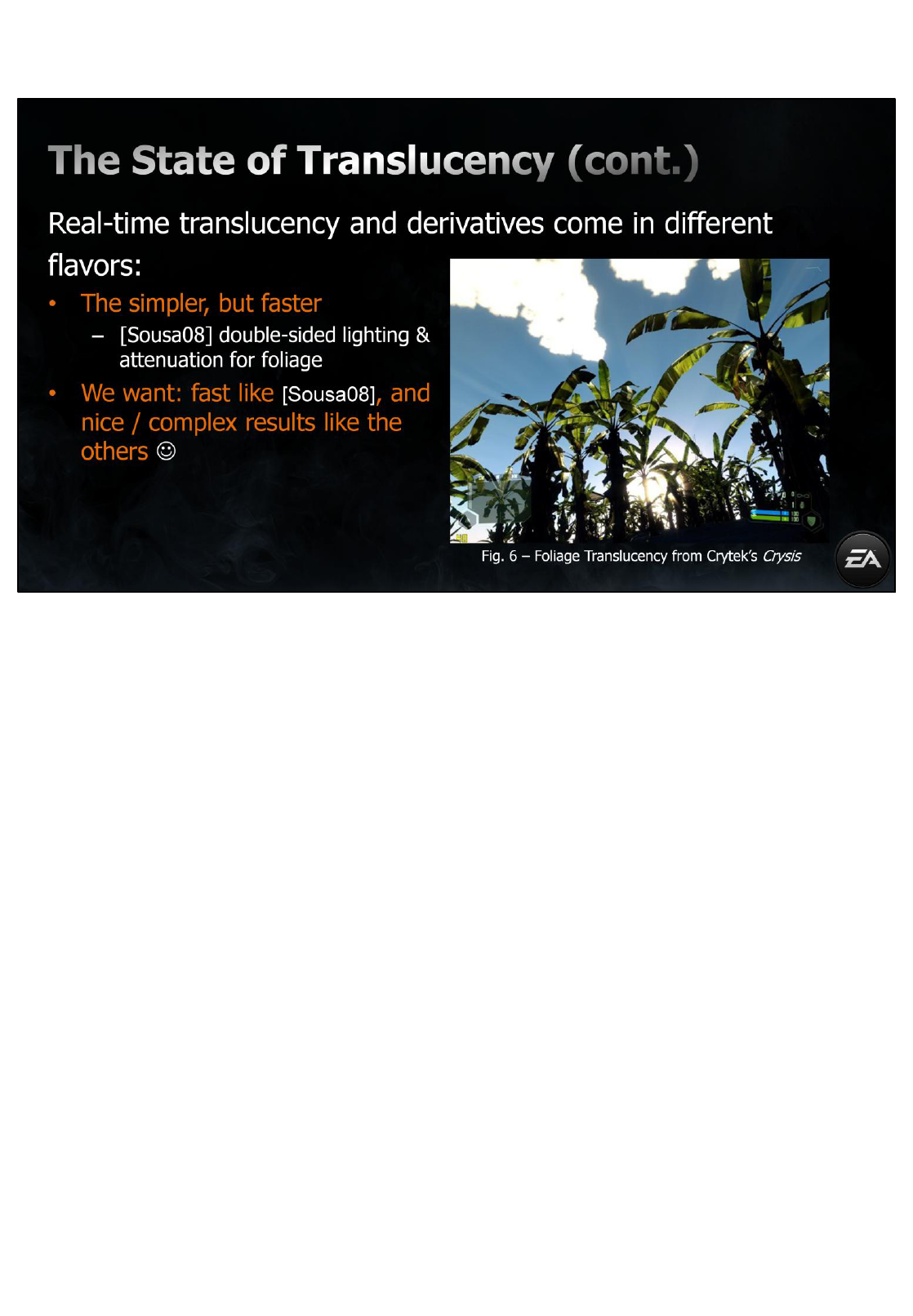
On the simpler, games like Crysis have used double-sided lighting with a gradient
mask texture to draw tree leaves with varying translucency. While this solution is
very convincing for the rendering tree leaves, it is not sufficient in the case one
wants to render objects of thicker volume. This is where our technique comes in
and fills the gap: it has to be efficient like the technique from Crysis, but get as
visually close as possible to those previously mentioned subsurface scattering
algorithms.
9

On the left, a scene with 3 lights running in Frostbite 2’s deferred shading engine, all of
which are using our real-time translucency technique, combined with real-time ambient
occlusion and real-time global illumination. On the right (but on the left as well), you can
see a cube that reacts differently from the other cubes: the light inside its convex hull is
green, but the surface partially emits a red veiny color (instead of the expected green).
This information, which we will describe soon, is provided on a per-material basis and
allows artists to author subsurface scattering-like results with ease. This additional
information allows us to describe how a surface should react if light travelled through its
hull.
10

Another example here, you can see to the left two hands with skin shading and real-time
translucency. Additionally, to the right, we’ve used the well-known Hebe for
representing light traveling inside stone-like surfaces, such as marble.
11

Now that we’ve introduced our technique, let’s spend a bit of time on some of the
technical details.
12

Again, we don’t want to rely on additional depth maps and texture space
blurs for simulating translucency. While the previously mentioned
techniques provide quite significant results, they require additional (and
sometimes a very significant amount of) memory and computation, which
we don’t necessarily have for our already-graphic-intensive first-person and
third-person games.
Moreover, with the current state of real-time graphics, several simple
elements can be combined together in order to convince the user that
objects in the world are actually translucent.
First, the light traveling inside the shape has to be influenced by the varying
thickness of the object. It also has to show some view and light-dependent
attenuation.
Overall, most users will be convinced if you can show the previous. Also, if
the effect is pretty cheap, you can use it everywhere and not limit yourself
to, say in-game cut scenes, where the more complex SSS techniques are
usually gloriously shown.
13

To achieve the previously mentioned, we begin by using distance-attenuated
regular diffuse lighting, combined with the distance-attenuated dot product of
the view vector and an inverted light vector.
This allows us to simulate basic light transport inside an object, for simple shapes
(such as cubes, spheres, etc…) because it takes advantage of the radial diffusion
properties of lights. However, this does not take thickness into account, and is
not visually-optimal for complex models. It is necessary to be aware of the
thickness, or rather the distance travelled by the light inside the shape, in order
to properly compute light transport inside that same shape.
We could do this with depth maps, since they define a referential, allowing us to
easily compute the distance travelled by the light from the light source through
the shape and to the pixel. Again, as mentioned earlier, we’re trying to not rely
on additional depth maps.
14

Instead, we pre-compute a map that defines local variation of thickness on an object. In
parallel, as seen in [Sousa08] (referring to Crytek’s Crysis real-time foliage technique), it
is possible for artists to define a texture where the values are approximately
representative of the leaf’s thickness: with dark values for opaque, and bright values for
translucent.
While this method works well for semi-flat surfaces such as tree leaves, in cases where
the environment has numerous translucent objects, shaped in various forms (such as
our statue here), the process of defining which areas on the shape are translucent is a
tedious manual process.
To streamline this, we rely on a normal-inverted computation of Ambient Occlusion
(AO), which can be done offline (using your favorite modeling and rendering software)
and stored in a texture. Since ambient occlusion determines how much environmental
light arrives at a surface point, we use this information for the inside of the shape (since
we flipped the normals), and basically averages all light transport happening inside the
shape.
Here's an example on the well-known Hebe. You can notice how thinner parts of
the mesh are more translucent than generally thicker parts.
15

To summarize, inverting the surface normal during the AO computation
approximates how much light travelling inside the homogenous media would get
occluded at the point where it exits the shape.
The result is a texture with inverted colors that depict two types of area:
translucent areas in white and opaque areas in black. Conversely, in cases where
you have a good level of tessellation, it is possible to store this information in the
vertex color, which is what we do for some non-Frostbite implementations on the
Wii.
Finally, we can use this information to improve the computation of light
transport, where the final result lays in-between real subsurface scattering and
distance-based attenuation. The inverted AO gives a feeling of scattering, i.e.
collecting light, while using a single distance value for distance-based
attenuation.
16

Here’s the local thickness map for our Hebe statue.
17

While our technique is far from being mathematically correct in terms of
approximating subsurface scattering, we still get a nice light transfer effect
because our local thickness texture is not limited to grayscale values. It can
indeed be colored.
This color allows us to get even more interesting results, since it basically
represents the color that the surface “emits”, though pre-computed, through the
scattering of light.
This basically means that if we know roughly what color our surface would get
through subsurface scattering, we can then store it in this texture.
Again, this is not mathematically correct (and technically far from what is
achieved by [Hable09] and others), but at the end of the day, if we manage to
make-believe that the surface has subsurface scattering, then we have
succeeded.
18

Now, some implementation details.
19

Here’s a quick overview of our final light transport code in HLSL.
Here, we combine the local thickness and our lighting vectors, as well as several
translucency-specific parameters, which we’ll describe in the following slides.
Also, just to give you a quick performance overview, this code only generates 13-15 ALUs
(based on the platform), runs on SM2.0+ hardware and semi-fixed pipeline systems,
such as the Wii.
20

Again, we have several parameters to manage in order to make this happen. At
runtime, some parameters will have to be defined per-light, and some per-
material. Our per-light parameters are pushed in the light pass, and the per-
material parameters are stored in the g-buffer.
Knowing the g-buffer is space-limited, you can also store these parameters in a
separate buffer (if translucency is a very important effect for your game). Also,
some parameters make more sense per-light and some per-material. Actually,
most of these parameters should be defined per-material, and a single one of
them (which we’ll see in the next slide) should be per-light. Based on how
flexible your g-buffer setup is, and how much control you want to give, you can
shuffle these around, per-light or per-material. Also, to save space, you might
have to do some packing/unpacking, which we’ll discuss a bit later.
21

First, we have an ambient term, which describes translucency visible from all
angles, at all times.
This term basically represents a minimum value of how much a translucent
surface constantly lets light go through, both visible if the surface is in front or
behind the light source (aka front and back translucency).
22

As a second parameter, we have a power attenuation which we use on the view-
oriented, back translucency.
While we usually want vient-independent effect, this power is very useful
because it will break the continuity in a view-dependent way, which will break
uniformity between back and front lighting/translucency, and make your results
much more organic.
As a quick note on optimization, we can create several pre-computed power
permutations, which can help with this “expensive” operation.
23

As a third parameter, we have a distortion value, which we use to shift the
inverted light vector based on the surface normal.
This factor will simulate subsurface light transport distortion, improving the
results and making everything even more organic, and almost Fresnel-like at
times. To the left, we have no distortion, and to the right we have a small distortion of
0.2.
As a side note, one might wonder why we don’t normalize vLTLight before
the dot product with the eye/camera vector. This is because the result of
the dot is clamped between 0-1 (saturate), and will only return the
backside lighting (since we use –vLTLight), which is what we want anyway
for back translucency.
24

Our light transport is modulated by the local thickness texture, which we pre-
computed previously, for both the front and ambient translucency. Again, this
texture attenuates the results where the object is “generally thicker”.
25

Finally, we have a scale value, for direct translucency. This scale basically defines
how much light will go through with the back translucency. On the image to the
left, we have a scale of 1, and a scale of 5 to the right.
[IMPORTANT]
Having this single parameter defined per-light, this will make results easier to
tweak at runtime. After all, artists will be able to set properties that make more
sense on per-material basis (such as power, distortion, and ambient): all
properties which in fact define how the _surface_ reacts to inner light transport.
Then, they will tweak how strong light transport is scaled, on a per-light basis,
with this single parameters. This also allows to unify surface types/materials and
reuse them in several contexts, without having to change many parameters, only
limited to a single scale value.
[/IMPORTANT]
26

Putting it all together, here’s our final result, of direct (front and back) and
ambient translucency. You can notice how the translucency slowly varies inside
the head, distorts on the contours of the shape, and is very prominent on the
nose.
27

On the engine side, translucency can be stored in the g-buffer as a single
greyscale texture. Here’s one of our g-buffer setups for Frostbite 2. In the case
where your g-buffer is very “busy” and full, you can store a single greyscale value
and achieve some very convincing results. Also, we filter by materialID, which
makes it so that this channel can be used for other types of materials.
28

Here’s an example with 3 lights where the objects are showing translucency using
a greyscale local thickness texture.
29

If greyscale local thickness is not enough, we can store it as a color. We recommend
experimenting with the grayscale implementation before moving on to the colored
version. Since we only have 1 channel left, we can reuse some channels based on the
material ID without losing too much flexibility. To get more out of the existing channels,
we reuse some of the GB2 based on Material ID. In our case, the material ID for the
translucency is the last one. If we add one of the local thickness texture’s channels
(here, the blue channel) to the material ID, we know for sure that the value in that
channel is indeed from the texture, since it is definitely higher (or equal) to the
translucency material ID. That in mind, we decided that we don’t want custom
environment maps for translucent materials, because most of these usually focus on
light traveling inside them, rather than light reflected on them (hence why we reuse the
custom envmap channel ID for these materials). But we have multiple g-buffer setups,
so we can shuffle this around.
Also, since we don't have that many material IDs, we don’t lose too much precision: our
local thickness texture's B channel has an offset of 3/255.0f. Also, variation in blue is not
as noticeable as variation in red and green (in regards to human perception). We could
remap by offsetting and scaling that channel when computing the translucency, but the
offset is not that noticeable. This also means that we can’t have parts on the material
that are completely opaque in terms of translucency, unless we remap. Generally, if that
was the case, one shouldn't mark that object as translucent and waste precious pixel
processing.
We also have another way of packing additional parameters in the g-buffer. With this
setup, one could precompute several ambient, power and distortion values, and spare
some bits from the translucency color channels and pack those with the color, leaving
the “scale” as the only parameter left to tweak on a per-light basis (and most likely the
only one you want to tweak per-light, since the other ones are rather material-specific
than light-specific).
30

Here’s a result with colored translucency. The cube on the left has a red local
thickness texture, but the light inside its convex hull is green, in comparison to
the object on the right, where the local thickness texture is greyscale.
31

In regards to our implementation on PS3, this technique takes advantage of our
light-tile renderer on SPUs. We basically divide the screen in multiple tiles, and
render translucency using SPUs only for tiles that have translucency. For more
information about this, you should definitely attend Christina Coffin’s talk on SPU
deferred shading.
Similarly, our DX11 implementation takes advantage of our compute shader
solution. For more info on this, and more DX11-specific optimizations and
performance metrics, you should definitely attend Johan Andersson’s talk.
Overall, these numbers illustrate that our technique approximates convincing
real-time translucency at a very reasonable cost. This method also provides
significant benefits in cases where developers want a quick impression of
subsurface scattering. In fact, the technique only requires 13-15 additional
instructions to achieve a significant and convincing effect, runs on SM2+, as well
as on the Wii.
32

Due to the fact that this technique is an approximation, and takes into account
radial properties of lights, some specific instances will not yield optimal results.
The figure here shows an example where light travels in and out of the concave
hull at point A, casting a shadow on point B.
While it is possible to generate local thickness that is aware of the concavity by
changing the parameters used for the ambient occlusion computation, this has to
be minimized when demonstrating visually convincing examples of diffuse
translucency. Our technique works more effectively with convex hulls.
Also, this technique doesn’t work for morphing objects. An alternative could be
to compute view-oriented screen-space thickness, as demonstrated in [Oat08],
but will only work if translucency results from indirect lighting. Additionally, one
could use an hybrid approach of real-time AO for computing the local thickness
on a morphing object, but this is getting complicated…
33

We presented an artist-friendly, fast and scalable real-time approximation of light
transport in translucent homogenous media.
Our technique allows developers to improve their game’s visuals by simulating
translucency with reasonable and scalable impact on the runtime.
Providing convincing results through simple means is essential in the development of
high-quality triple-A games.
We also hope that this technique will inspire developers in the continuous effort to
improve games by promoting the development of new techniques that carefully blend
art and technology, where convincing results don’t always require exact math.
34

Now, some implementation details.
35

Marc and I would like to thank the following people for their time, multiple reviews and
never-ending support!
36

37

38
