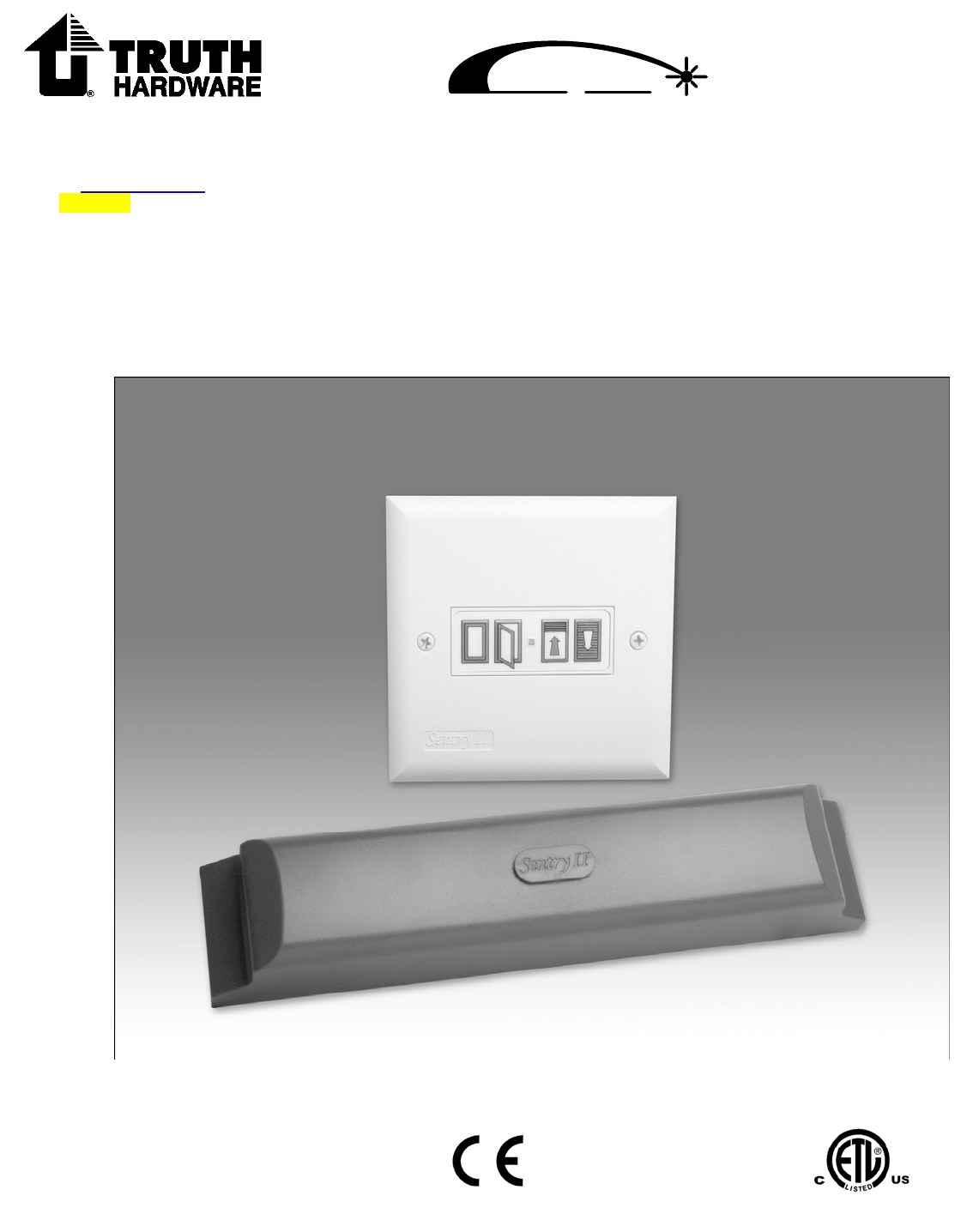
Sentry II
TM
Made in USA
An FKI Industries Company
700 West Bridge Street
Owatonna, MN 55060
www.truth.com
Form 90063 R2
Window or Light Skylight
Motorization System
Installation Instructions

Did you find what you’re looking for? The Truth Hardware Web site is a great resource for
the latest product and installation information. It’s available at www.truth.com
2
Danger: To help prevent severe personal injury or death:
• Read and understand instructions completely before beginning
installation.
• Wiring must be installed by a qualified electrician according to
local and National Electrical Codes (N.E.C.)
• Disconnect main power before beginning installation! Verify
that power is OFF at the main breaker or fuse panel by testing
with a voltage meter that you know is working correctly.
• Connect power only after motor connections and settings are
verified.
• This equipment does not provide a method to shut off power,
and should be connected to a dedicated breaker or fused
power circuit capable of providing 1 amp at 120 VAC of power
per window unit.
• The screen interlock MUST be correctly installed and is a
required part of the power window system. It is intended to
help prevent injury that could result from reaching into the
window area during operation. The correct installation of the
screen interlock is the responsibility of the installer. (The
screen interlock is not required on windows and skylights
installed more than 8 feet above the floor.)
• Do not allow children to operate the wall push buttons or
remote control transmitter(s).
Additional Safety Guidelines
• When connecting the Sentry II system to accessories, read the
installation instructions supplied with each accessory before
beginning installation.
• The Sentry II system must not be used on windows intended
to meet egress codes.
• The Sentry II system is intended for indoor use only, with
screens in place.
• Save ALL instructions. Additional copies can be downloaded
off of our web site at: truth.com\technicalsupport
• Installer – please be sure to give ALL instructions to the
homeowner once installation is complete.

Did you find what you’re looking for? The Truth Hardware Web site is a great resource for
the latest product and installation information. It’s available at www.truth.com
3
[
What you should know before starting....4
Parts List ....................................................5
Planning......................................................6
Inspect Windows........................................7
Battery Backup ..........................................8
Motor Installation ......................................9
Controller Installation ...............................14
Main Wiring Diagram.................................17
Normal Operation.......................................20
Rain Sensor................................................21
HPI...............................................................22
Power Blind Control ..................................23
Common Problems....................................24
System Reset ............................................26
Service .......................................................27
Status Light Code......................................28
Control Box Cut-Out Template .................29
Regulatory Compliance.............................30
Getting Started
Set Up
Installation
Troubleshooting
Table of Contents
Operation
Accessories
Additional Info
Preparation

Did you find what you’re looking for? The Truth Hardware Web site is a great resource for
the latest product and installation information. It’s available at www.truth.com
4
Supply Voltage Note: The supply voltage range for the Sentry II power window
system is very flexible to accommodate supply voltages available from many
different countries. The input (supply) voltage range is 90 to 264 VAC at a
frequency range of 47 to 440 Hz. For practical purposes, the supply voltage
referenced in this document is 120 volts at 60 Hz commonly used in the United
States.
Operating Environment: The control unit must be located in a dry environment
which includes protection from condensation. The operating temperature range
must be maintained between 140º F (60º C) to -5º F (-20º C).
Be sure the motor system will fit in your application: The Sentry power
window system is intended to fit onto casement, awning and skylight hardware
manufactured by Truth Hardware only. In many cases you will be able to identify
our hardware by our logo ( ) somewhere on the hardware. When in doubt, the
best way to tell is if the spline adaptor fits onto the operator stem in place of the
crank handle – see Motor Installation step 2 .
The Sentry II power window will not work in the following applications:
• Fitted to any type of jalousie window
• Fitted to any type of door
• Fitted to any type of cable controlled window system - Such as those
manufactured by Clearline or Ultra-Flex
• Fitted to any type of in-swing window
• Fitted to any type of manual skylight hardware manufactured by Velux or
Roto
Any use of the Sentry II power window system not approved by Truth
Hardware is at the user’s own risk.
Be sure the motor system is compatible with your application: It is
important to understand that the design parameters of the Sentry II power
window system are predicated on a properly functioning manual window system.
This includes the rotary operators and
hinges installed on the window. It is the
responsibility of the window manufacturer and/or the window specifier to insure
the window size and weight fall within the specifications of the manual hardware
system installed on the window. If the window size and/or weight fall outside of
the hardware specifications, the motor system may not function properly. If the
window carries an AAMA (American Architectural Manufacturers Association)
label chances are the window system meets all hardware requirements.
However, if the window does not carry an AAMA label you may want to contact
the window manufacturer to verify the windows have been manufacturer within
the hardware manufacturer’s specifications - especially if the window size is
unusually large and/or of unusual proportions.
What You Should Know Before Starting
Did you find what you’re looking for? The Truth Hardware Web site is a great resource for
the latest product and installation information. It’s available at www.truth.com
5
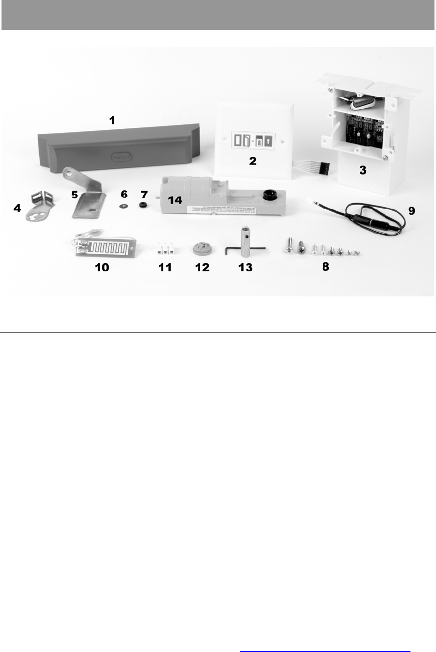
Parts list Part number
1. Motor Cover 12490.XX (not part of kit)
2. Control unit cover plate 12488
3. Wall mounted control unit 12592
4. Mounting bracket – Window *
5. Mounting bracket – Skylight ** Parts 4 thru 13 are in
6. Push on fastener hardware pack 12492
7. Isolation grommet
8. Screws
9. Screen interlock
10. Rain sensor Replacement part #22123
11. Terminal block
12. Strain relief
13. Spline adapter and wrench
14. Motor unit 12547.00.0001
Installation instructions (not pictured) 90063
* Window bracket may look slightly different.
** Skylight bracket is not included with all kits.
XX Indicates a color selection
Note:
• No wire is included. See wiring diagram on page 17 for wire requirements.
• To replace broken parts, please go to www.truth.com/technicalsupport
Getting Started

Did you find what you’re looking for? The Truth Hardware Web site is a great resource for
the latest product and installation information. It’s available at www.truth.com
6
Planning
Important: If you are not the homeowner, it is important to contact the
homeowner and discuss how they want to control a group of windows and/or
skylights. It may be very difficult to change the installation to meet the
homeowner’s desires once installation is complete.
Please consider:
• If installing more than one power window system, each motorized window
must
have its own control unit. If there are multiple windows and/or
skylights installed and it is desired to have a single control point for all
windows and skylights, the wireless RF remote control will give you this
option. Since the remote control uses RF communication technology it is
not restricted to line-of site limitations. (See remote control operating
instructions for more information - also available at
truth.com/technicalsupport)
• The control unit will give convenient wall mounted control only for the
window connected to it. If the wall mounted control is not intended to be
the primary means of control you may want to consider mounting it in a
remote, out-of-the-way location.
• All Sentry II control units are Remote Control enabled. This allows you the
convenience of adding an optional remote control at any time.
• If you are installing the motor system onto a window that has manual locks
be sure the locks are unlocked manually before attempting to open.
Power sash locks are an available option for some windows.
• The Sentry II power window system does not have manual override in
case of a power outage. If it is important to be able to close the windows
without power, consider installing a battery back-up system.
• There are a number of other control options available:
o Remote Control Has Built-in Thermostat - For those applications
where it is desirable to open and close your windows or skylights
based on temperature, please be aware that the optional remote
control has a built-in thermostat. Just set the temperature and
place the remote in the area where you want the temperature
controlled.
o Rain Sensor - A rain sensor comes standard with each unit. If you
choose to install the rain sensor option, each control unit needs a
separate rain sensor. Consult main wiring diagram for wiring
requirements if used. List max dist.
o Power Sash Locks - The optional power sash locks require
additional wires to be run from the control unit to the window.
Consult main wiring diagram for wiring requirements if used.

Did you find what you’re looking for? The Truth Hardware Web site is a great resource for
the latest product and installation information. It’s available at www.truth.com
7
o Power mini blinds - The Sentry II control unit is capable of
controlling power mini blinds (supplied by others) in addition to the
window motor and sash locks. See page 23 for additional
information. Consult main wiring diagram for wiring requirements if
used.
o Window status feedback - The Sentry II control unit is capable of
providing window position feedback (open or closed). See page 23
for additional information. Consult main wiring diagram for wiring
requirements if used.
o Integrated control with other control systems - The Sentry II
power window system can be integrated with other automated
control systems. Some examples are home automation systems,
thermostats and security systems. See page 22 for additional
information. Consult main wiring diagram for wiring requirements if
used.
• Each control unit requires 1 amp of power at 120 VAC.
• Plan your wiring routes carefully. Low voltage wires must not be run
parallel to high voltage wires. Be sure to use shielded, twisted pair wiring
in electrically noisy environments.
Set Up
Inspect Windows
The windows and/or skylights must operate correctly and smoothly. Lubrication
or cleaning of hardware may be required. This motor system will not operate
correctly if the manual hardware is not functioning properly.
Important Skylight Information:
• When installing the Sentry II motor on a skylight,
the skylight lid must weigh less than 40 lbs. at the
chain. A hand crank should be used to verify the
skylight operates smoothly.
• When installing on a skylight, the motor system will
only fit the angle drive model manufactured by
Truth Hardware shown in step 3. Verify the
skylight operator you have looks like the one
shown in step 3.
Skylight lid must
weigh less than
40lb (18 kg) at the
chain

Did you find what you’re looking for? The Truth Hardware Web site is a great resource for
the latest product and installation information. It’s available at www.truth.com
8
Battery Backup
Battery backup should be used to supply emergency power when operation of
the power window system must be maintained in the event of a power outage.
(Please note: A battery back-up is not required to provide memory back-up for
the Sentry II system.)
Truth recommends the use of a UPS (uninterruptible power supply) as a battery
backup. They are widely available through a variety of retail and commercial
outlets and are primarily used to supply emergency backup for computer
equipment. (Truth Hardware is not a supplier of battery back-up systems.)
To determine the proper VA rating for a UPS, take 50 watts and multiply by the
number of windows and/or skylights to be backed up by a given UPS. Below is a
list of the manufacturers who produce uninterruptible power supplies which we
have approved as compatible with our power window systems.
Powerware
Forum III
8609 Six Forks Road
Raleigh, NC 27615
(800) 554-3448
(919) 872-3020
www.powerware.com
American Power Conversion
132 Fairgrounds Road
West Kingston, RI 02892
(800) 788-2208
(401) 789-5735
www.apcc.com
Tripp Lite
1111 West 35th Street
Chicago, IL 60609
(773) 869-1111
www.tripplite.com
Minuteman (brand)
1455 LeMay Drive
Carrollton, TX 75007
(800) 238-7272
(972) 446-7363
www.minuteman-ups.com

Did you find what you’re looking for? The Truth Hardware Web site is a great resource for
the latest product and installation information. It’s available at www.truth.com
9
Installation
Up
Motor Installation
Note: Window operators are usually mounted to the bottom sill of the window.
Occasionally the operator will be mounted on the side jamb of an awning or
casement window and also occasionally to the head of a hopper window. These
are all acceptable applications provided the window opens and closes smoothly
throughout its full range of motion. Be sure the motor system is mounted
securely to the window in these applications.
1. Test hand crank
a. Determine the direction of hand crank rotation to open the window as
either Clockwise or Counter Clockwise (when facing the window operator).
b. Circle the direction to OPEN below. (This information will be needed for
proper system setup in Step 5.):
Note: The window or skylight can be in any position while installing the Sentry II
motor. However, leaving the window or skylight partially open is helpful in testing
system operation. When power is supplied to the motor for the first time, the
control system is programmed to close the window. A closing window upon
power-up will therefore confirm that the motor is receiving power and wiring
polarity is correct. If the window is closed during motor installation, a short
noticeable hum will confirm that the window is receiving power.

Did you find what you’re looking for? The Truth Hardware Web site is a great resource for
the latest product and installation information. It’s available at www.truth.com
10
2. Install adapter
Before installing the spline adapter determine how the adapter should be applied
to the type of window operator that you have.
If your window operator is similar to the picture shown below (some operators
may have the worm on the other side of the operator case) please switch the set
screw to the hole at the opposite end of the adaptor before installing on the
operator shaft. For all other operators, apply the adapter as it was shipped to
you.
If the operator looks
similar to the one
shown on the left
please move the
set screw from the
hole that it was
installed in for
shipping to the
open hole at the
opposite end of the
adaptor
After installing the spline adapter (B) onto operator
shaft, tighten set screw with wrench (A).
NOTE: Be sure the set screw is fully seated into the
operator shaft groove.
3. Choose wire location
Plan wire exit location on window for
• Operator motor
See figure 3a below for casement and awning windows and Figure 3b for
skylights
Note: Be sure the window width will accommodate the motor width. See
Fig.s 3c & 3d below for finished dimensions.
• Power sash lock (if used)
Consult power sash lock installation instructions
• Power mini blinds (if used)
Consult power mini blind installation instructions
A

Did you find what you’re looking for? The Truth Hardware Web site is a great resource for
the latest product and installation information. It’s available at www.truth.com
11
Figure 3a
Note: The placement information above
are guidelines only. In some cases it is
better to do a trial fit of the motor onto
the operator. Hold the motor square and
check both sides while looking for
interference between the motor housing
and operator housing.
Figure 3b
Figure 3c
Finished dimensions of motor system applied to a casement or awning window.
Figure 3d
Finished dimensions of the WLS motor system applied to a skylight window.

Did you find what you’re looking for? The Truth Hardware Web site is a great resource for
the latest product and installation information. It’s available at www.truth.com
12
4. Mount the motor
a. Slide motor over spline adapter (B).
b. Insert the isolation grommet (D) into the mounting bracket where it
best lines up with the motor mount post.
Note: If a number of mounting positions are provided by the bracket,
use the one which provides the best alignment with the window frame.
c. Secure motor with bracket (C).
Note: In window applications two screws should be used when
mounting the bracket (C) to wood or plastic window frames.
d. Slide the push-on fastener (E) over the motor post to secure the
motor to the bracket and window casing.
Warning: The push-on fastener is required for safety. Failure to install
the fastener (E) can cause the motor to become detached and fall from
window.
Window Mount
Sheet metal screws: (2) #8 x 5/8” Ph PH
Skylight Mount
Machine screw : (1) #12-24 x 1” Ph PH
5. Align and tighten collar
Align motor to window and tighten
set screw in black plastic alignment
collar (F) with wench (A).
Warning: Do not over tighten. Damage
will occur to alignment collar if it is
tightened excessively.
A
B
B

Did you find what you’re looking for? The Truth Hardware Web site is a great resource for
the latest product and installation information. It’s available at www.truth.com
13
6. Install screen interlock!
Install screen interlock (G) to the
face of the screen frame as shown
using the supplied pan head
screw (H). Refer to Main Wiring
diagram for connection
information.
WARNING: The screen interlock
must be installed on windows or
skylights less than 8 ft from the floor.
It is intended to prevent personal
injury and/or window damage during
operation
Self threading machine screw: #6-32 x 3/8” Ph PH
7. Secure wires and *install cover
a. Connect motor wires per wire
diagram (see page 17) and
secure with tape.
b. Install the motor cover using
the 6X3/8 PH screw (I) found
under cover button (J).
* WARNING: Use of a longer screw ()
will damage the motor and void the
warranty Use only the screw provided
for the motor cover (No. 6-32 X 3/8
Phillips pan head machine screw).
J*

Did you find what you’re looking for? The Truth Hardware Web site is a great resource for
the latest product and installation information. It’s available at www.truth.com
14
Controller Installation
1. Prepare wall for control unit
Note: A control unit is required for each motorized window. Connecting two
or more window motors to one control unit will overload and damage the control
unit and void the warranty. Multiple windows can be controlled from a single
control point via the optional RF remote control.
Important: The control unit is supplied with a protective cardboard shield to
protect the delicate control circuits from construction debris during the “rough-in”
building phase. Depending on the severity of construction debris expected at the
construction site, additional shielding may be required. Sealing the unit with duct
tape or some other means until the final wiring phase may be required.
If the install location already has a finished wall with unexposed studs, jump
ahead to page 15 and follow steps for “Finished Wall.”
Open Wall: Step 1
Locate the desired mounting
location for the wall control unit.
Mount control box onto the selected
wall stud with screws (not included)
at the desired height. Using the
template provided on page 29, mark
and cut the prescribed hole in wall
board for the intended application.
Open Wall: Step 2
Route and install wires - Route low
voltage wires from motor location
(including any accessory wires, such
as rain sensor, power blind, etc...) into
control switch opening. (See main
wiring diagram on page 17 for
complete wiring specifications.) Route
appropriate high voltage wire and
select an inlet on control box which
works with the selected orientation.
Remove knock-out and install strain
relief provided. Pull 120 VAC wiring
into control box through strain relief.
Skip “Finished Wall” steps 1 and 2.
Advance to page 16.
Break off
tabs (4)
Strain
Relief

Did you find what you’re looking for? The Truth Hardware Web site is a great resource for
the latest product and installation information. It’s available at www.truth.com
15
Finished Wall: Step 1
Locate the desired mounting location
for the wall control unit. Verify the
location of interior wall studs before
selecting the mounting orientation of
control box.
Using the template on page 29 of this
instruction booklet, mark and cut wall
opening. (Cutout size is 3 7/8 inches
Wide X 4 1/8 inches High) Note that a
portion of the wall box is hidden inside
the wall cavity, and that the box and wall
plate can be mounted in any direction
required.
Finished Wall: Step 2
Install Control Box
a. When installing the box after
the wall is finished the
mounting wings should be cut
off and discarded.
b. Insert control box into wall
opening.
c. Secure box to wall by
tightening clamp screws.
The wall clamps engage the wall
automatically as the screws are
tightened.
d. Route low voltage wires from
motor location (including any
accessory wires, such as rain
sensor, power blind, etc...) into
control switch opening.
See main wiring diagram on page
17 for complete wiring
specifications. Route appropriate
high voltage wire and select an
inlet on control box which works
with the selected orientation.
Remove knock-out and install
strain relief provided. Pull 120
VAC wiring into control box
through strain relief.
Clamp screws
Cut Off
Mounting
Wings
High
Voltage
Wires
Wall Box
Installed.
Use template located on page 29 to mark
cutout location and cut as required.
Orientation can be rotated if desired
Low
Voltage
Wires

Did you find what you’re looking for? The Truth Hardware Web site is a great resource for
the latest product and installation information. It’s available at www.truth.com
16
Danger: Power supplied to high voltage (120 VAC) wiring should be
disconnected at main breaker panel or through other means. This motor control
will need 1 amp of current at 120 VAC.
Note:
• Installation must meet local and national electrical codes.
• Refer to main wiring diagram for wire size and type requirements.
• Plan your wiring routes carefully. Low voltage wires must not be run parallel to high
voltage wires.
• Be sure to use shielded, twisted pair wiring in electrically noisy environments.
4. Connect Wires per wire diagram
Remove protective cardboard shield. Connect low voltage wires for operator
motor and all accessories to the control unit as diagramed on the main wiring
diagram (page 17). See terminal blocks 1 thru 5. (Do not apply power until step
7!)
Note:
1. Terminal blocks are rated for 16 to 20 gauge solid core wire. If wire runs are such
that wire sizes exceed 16 gauge, wire must be spliced down to a 16 to 20 gauge wire
before connection to terminal blocks. Keep reduced wire size length to a minimum
length. Use solid core wire only for connection to the control unit! Do not use
stranded wire.
2. Install and connect optional power sash locks at this time if used. Consult installation
instructions supplied with lock for proper installation.
5. Set Function Dip Switches
The purpose of setting the dip switches is to properly configure the electronic
control system to the type of window and window accessories to be controlled.
(See S2 on wire diagram)
1
2
34
5
6
on
off
1 – Must stay set to “on”
2 – Motor Application:
If the motor is installed on a window, set
to “off”
If skylight, set to “on”
3 – Drive motor direction to open (from Step 1)
CW = “off” OR CCW = “on”
4 – Motorized Blinds:
No Blind present = “off”
Blind connected = “on”
5 & 6 – Motorized Locks
No Locks = 5 & 6 both “off”
One Lock = 6 “on” & 5 “off”
Two Locks = 6 “off” & 5 “on”
Note: Dip switch settings must be made with 120 volt supply disconnected.
Did you find what you’re looking for? The Truth Hardware Web site is a great resource for
the latest product and installation information. It’s available at www.truth.com
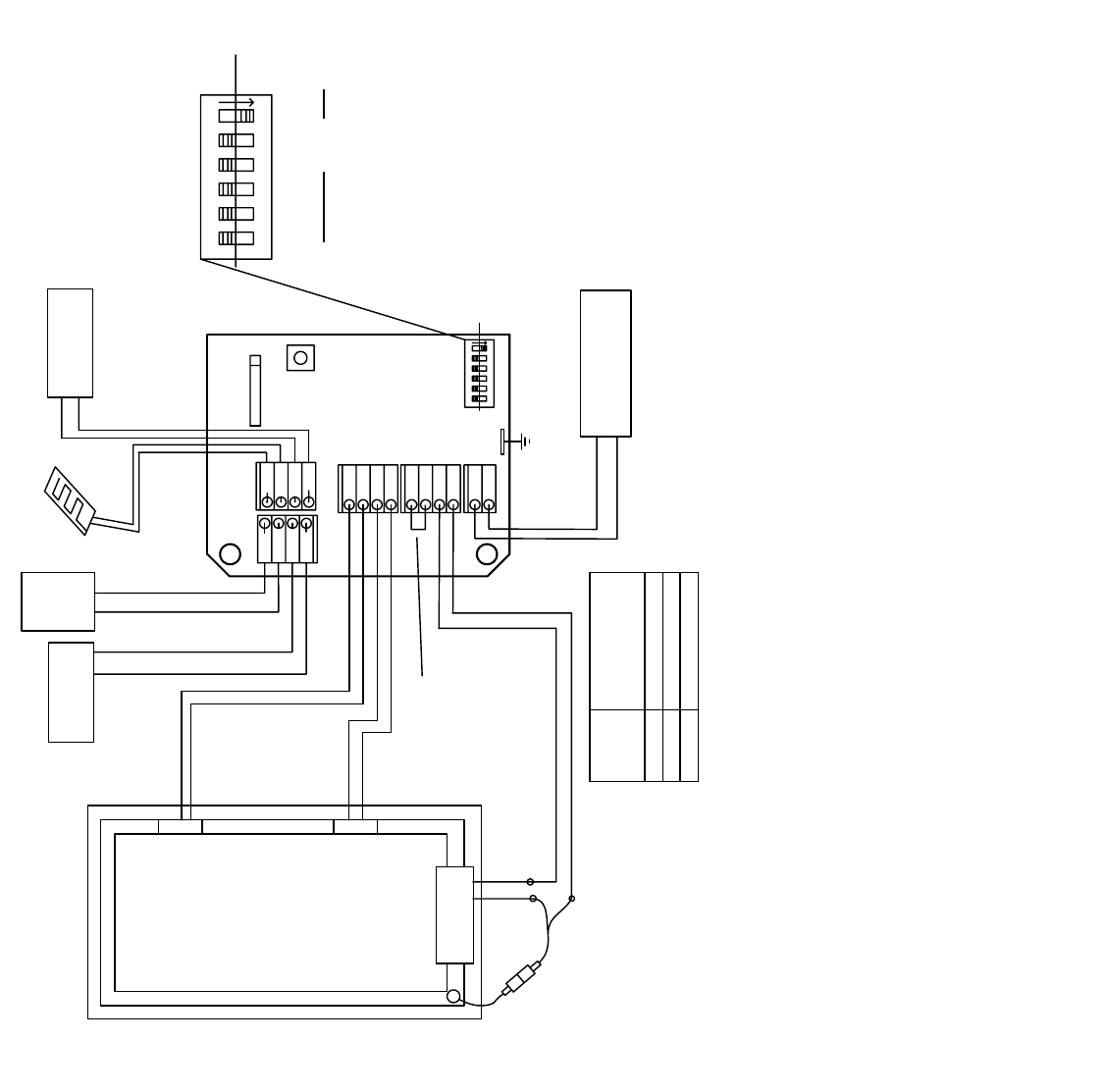
17
Grey
Green
Grey
Grey
Grey
Green
Green
Green
W
h
i
t
e
W
h
i
t
e
W
h
i
t
e
G
r
e
y
G
r
e
y
R
e
d
B
l
a
c
k
B
l
u
e
B
l
u
e
B
l
u
e
12
10
7
5
4
Motor
Lock 1
Lock 2
R
e
d
B
l
a
c
k
R
e
d
B
l
a
c
k
Screen
Interlock
R
e
d
B
l
a
c
k
B
l
a
c
k
B
l
a
c
k
J
u
m
p
e
r
(
f
a
c
t
o
r
y
i
n
s
t
a
l
l
e
d
)
S
e
e
S
t
e
p
5
+
-
Blind mot or
+
-
S2
S1
12
34
5
6
on
off
H
P
I
"
o
p
e
n
"
J1
R
a
i
n
S
e
n
s
o
r
W
h
i
t
e
W
h
i
t
e
S2
1
2
34
5
6
on
off
1
-
Must stay set to "on"
2
-
Mot or Application:
W
i
n
d
o
w
a
p
p
l
i
c
a
t
i
o
n
=
"
o
f
f
"
S
k
y
l
i
g
h
t
a
p
p
l
i
c
a
t
i
o
n
=
"
o
n
"
3
-
Drive motor direction to Open:
C
W
=
"
o
f
f
"
O
r
C
C
W
=
"
o
n
"
4
-
Motorized Blind:
N
o
B
l
i
n
d
p
r
e
s
e
n
t
=
"
o
f
f
"
B
l
i
n
d
c
o
n
n
e
c
t
e
d
=
"
o
n
"
5&6
-
Mot ori z ed locks:
N
o
l
o
c
k
s
=
5
&
6
b
o
t
h
"
o
f
f
"
O
n
e
l
o
c
k
=
6
"
o
n
"
&
5
"
o
f
f
"
T
w
o
l
o
c
k
s
=
6
"
o
f
f
"
&
5
"
o
n
"
Function Settings for Dip Switches:
Wire Size
(Class 2)
T
o
t
a
l
d
i
s
t
a
n
c
e
f
r
o
m
C
o
n
t
r
o
l
t
o
f
a
r
t
h
e
s
t
m
o
t
o
r
o
r
l
o
c
k
1
8
A
W
G
*
1
4
A
W
G
*
1
2
A
W
G
5
0
f
t
(
1
5
m
)
M
a
x
.
1
0
0
f
t
(
3
0
m
)
M
a
x
.
1
5
0
f
t
(
6
0
m
)
M
a
x
.
S
o
l
i
d
C
o
r
e
W
i
r
e
R
e
c
o
m
m
e
n
d
e
d
.
R
e
f
e
r
t
o
C
l
a
s
s
2
c
o
d
e
s
*
S
e
e
S
t
e
p
4
,
N
o
t
e
1
E
a
r
t
h
G
r
o
u
n
d
f
o
r
a
c
c
e
s
s
o
r
i
e
s
Main Wiring Diagram
O
p
e
n
C
l
o
s
e
S
t
a
t
u
s
+
-
H
P
I
"
c
l
o
s
e
"
G
r
e
y
W
h
i
t
e
R
a
i
n
S
e
n
s
o
r
w
i
r
i
n
g
:
2
2
-
2
s
h
i
e
l
d
e
d
,
t
w
i
s
t
e
d
p
a
i
r
U
p
t
o
5
0
f
t
(
1
5
m
)
M
a
x
.
H
P
I
O
p
e
n
,
H
P
I
C
L
o
s
e
&
S
t
a
t
u
s
w
i
r
i
n
g
:
1
8
-
2
t
w
i
s
t
e
d
p
a
i
r
U
p
t
o
1
5
0
f
t
(
6
0
m
)
M
a
x
.
N
o
t
e
:
T
w
i
s
t
e
d
p
a
i
r
b
e
c
o
m
e
s
m
o
r
e
i
m
p
o
r
t
a
n
t
i
n
n
o
i
s
y
e
n
v
i
r
o
n
m
e
n
t
s

Did you find what you’re looking for? The Truth Hardware Web site is a great resource for
the latest product and installation information. It’s available at www.truth.com
18
6. Connect power wires
Connect supply voltage wires (120 VAC)
to the wire harness and connector as
shown.
Danger: to avoid possible electric shock
power must be shut off at the main breaker
until installation is complete.
7. Plug in and install cover plate
Plug in the ribbon cable from
the wall plate onto control
board (See No. J1 on main wiring
diagram, page 17)
Note: Orientation of plug is critical
to correct operation of wall switch
and LED indicators. See note in
adjacent diagram.
Helpful Hint: The cover plate is only available in one configuration and color.
The cover plate can however, be painted or wall paper can be applied to change
its appearance.
Ribbon Cable has a shiny side
with silver traces and a dull side
with green traces. Install with
dull side (green traces) facing
towards you as shown.

Did you find what you’re looking for? The Truth Hardware Web site is a great resource for
the latest product and installation information. It’s available at www.truth.com
19
8. Apply power
Apply power to the control unit
Note: Upon power-up the window
should
close. (If window is closed,
motor will momentarily hum.)
If the window opens refer to the
window crank direction in step 1 and
dip switch settings in step 5.
• Disconnect power
• Change dip switch 3 on S2
(Refer to step 5.)
• Reapply power
The window should now close.
Note: Do not disconnect power while
the window motor is running.
9. Program remote control*
If optional remote control was purchased, it can now be programmed to the
control unit. Refer to set-up instructions included with the remote control.
*If the installation does not include a remote control, skip to step 10.
10. Establishing operating memory
Press “Open” button.
Please note:
• Upon pressing the open button for the very first time after original
power up, the unit will automatically run through an initialization
cycle, fully opening and closing the window (this may take up to 3
minutes depending on application).
• During this time the switch face plate will display a “Red” LED.
• This cycle is necessary for the unit to establish its operating
parameters which will be stored in permanent memory.
• Once permanent memory is established it is unaffected by loss of
power of any duration.

Did you find what you’re looking for? The Truth Hardware Web site is a great resource for
the latest product and installation information. It’s available at www.truth.com
20
Normal Operation
Note: If the window has manual locks the window must be unlocked before
motorized operation.
Buttons located on wall switch:
To open:
• Press “Open” on either the wall switch or the remote control to fully open
the window. If motorized locks are present they will function as part of
the window by unlocking and locking automatically.
Note: The full open position of a window will vary depending on
operating hardware and sash width. The typical open position is
approximately 70 to 80 degrees. Full opening can be achieved by
pressing the open button repeatedly once the window has stopped.
To close:
• Press “Close” on either the wall switch or the remote control to close the
window.
To stop the window in an intermediate position:
• Press the opposite button while the motor is running (such as pressing
“Close” while the window is opening) will stop the motor. The motor is
restarted by pressing either “Open” or “Close” again.
Status Light Indicator
• During motor operation the status light in the center of the wall plate will
be green to indicate normal operation. (See “Status Codes” on page
28 for more information.)
Status
Light
Open
Window
Or
Skylight
Close
Window
Or
Skylight
Open
Blind
Close
Blind

Did you find what you’re looking for? The Truth Hardware Web site is a great resource for
the latest product and installation information. It’s available at www.truth.com
21
Optional Accessories
Rain Sensor (included)
The sensor will close the window when “beading” moisture is present on the
surface of the rain sensor grid. It will also cause the green LED on the wall plate
to blink (indicating moisture is present). Once the panel is dry, normal operation
is regained.
Note:
• Connect the supplied sensor panel to the grey and green terminals on
Block 5 (see main wiring diagram, page 17). The window can be forced to
open even when the sensor is “wet” but the motor will immediately re-
close the vent.
• There is a 10 second delay from the time the rain sensor senses moisture
to the time the window actually starts to close.)
Rain Sensor Guidelines:
• Install the sensor with "grid" exposed to outside elements where the rain
has a clear, unobstructed path to the rain sensor. Consider prevailing
winds.
• Wire with 22 AWG - 2 conductor shielded, twisted pair 50 ft (15m)
maximum length
Warning: Connect shield to earth ground to reduce interference from
lightning and other electrical devices.
• The sensor can be mounted outside (maximum sensitivity) or inside vent
edge (minimum maintenance)
• Maintenance; Regular cleaning of sensor panel with a mild cleaning agent
is recommended. Dirt or debris can cause the vent to stay closed even
when rain is not present.
Warning:
• When used on skylights, do not route rain sensor wire through the chain
port, damage to wire will be a likely result.
• Do not install the rain sensor if venting of the window or skylight using the HPI
inputs is more important than closing due to rain. The rain sensor overrides all
other inputs. (see HPI, page 22).

Did you find what you’re looking for? The Truth Hardware Web site is a great resource for
the latest product and installation information. It’s available at www.truth.com
22
High Priority Inputs (HPI)
The control unit includes inputs to allow window control from other devices such
as thermostats, home automation systems, security systems, etc. These inputs
are called High Priority Inputs (HPI). There is an input for “Open” and an input
for “Close”. The inputs are designed to be controlled with low voltage dry
contacts (relay).
Note: See main wiring diagram on page 17 for proper connections.
• Input Function - HPI Close:
1. When connected by a continuous contact closure, the window will
close. All other input devices (except for Open & Hold) will be
“locked-out” until the contacts re-open. Do not attempt to open
until window is closed otherwise system may become confused.
2. When connected by momentary contact closure, the window will
close. There will be a minimum delay of 3 seconds before system
will react.
If window is “opening” (in motion) when a momentary “Close” is
received, the motor will stop. In this way a partial open position
can be achieved.
• Input Function - HPI Open:
1. When connected by a continuous contact closure, the window will
open. All other input devices will be “locked-out” until the contacts
re-open. There will be a minimum delay of 3 seconds before
system will react. Do not attempt to close until window is opened
otherwise system may become confused.
2. When connected by momentary contact closure, the window will
open. There will be a minimum delay of 3 seconds before system
will react.
If window is “closing” (in motion) when a momentary “open” is
received, the motor will stop. In this way a partial open position can
be achieved.
Important:
• Voltage supplied by HPI input is: 12 VDC @ 5mA. For
reference only.
• When multiple input sources are used to control a given set of
windows consult the Input Command Priority Table on the Truth
Hardware Web site to insure you receive the proper window
response to multiple input command sources.

Did you find what you’re looking for? The Truth Hardware Web site is a great resource for
the latest product and installation information. It’s available at www.truth.com
23
System Status Feedback
The Sentry II control unit is capable of providing feedback regarding whether
the window is closed or not closed. It will not provide true window position
other than closed.
Note: See main wiring diagram on page 17 for proper connections.
Status output function:
• The status output functions as a relay. When the output is
closed (relay contacts closed), the window is fully closed. When
the output is open (relay contacts open), the window is not fully
closed.
• Feedback output (contact closure) maximum ratings:
Rated Load: 0.50 A at 125VAC, 1 A at 24VDC
Minimum Load: 1mA, 5VDC
Max. operating voltage: 125 VAC, 60 VDC
Max. operating current: 1A
Max. switching capacity: 62.50 VA, 30W
Power Blind Control
The Sentry II control unit is capable of controlling 24 VDC blinds or shades.
Truth Hardware does not supply power blinds or shades. We only supply a
means to conveniently control them with the Sentry II control system. This allows
for a more convenient installation by combining the control of power blinds into
the same control system that opens and closes the windows. Therefore, it is
very important to choose a power blind system that is compatible with the Sentry
II control system.
Please use the following electrical specifications:
• Operating Voltage: 24 VDC
• Maximum current draw: 1 amp (at 24 VDC)
• Power blind system must be range protected with internal limit
switches.
Note: Truth Hardware does not supply the installation instructions for the
installation of the motorized blinds themselves. Please consult instructions
supplied with the blinds for installation.

Did you find what you’re looking for? The Truth Hardware Web site is a great resource for
the latest product and installation information. It’s available at www.truth.com
24
Control unit setup for Power Blind installation:
• Locate DIP switch block on the control unit labeled “S2”. (See main
wiring diagram on page 17.) Set DIP switch #4 to the “on” position.
• Consult blind installation instructions for proper blind motor polarity.
Locate the positive wire to open the motorized blind. Connect it to the
“Grey” terminal on terminal block #12. (See main wiring diagram.)
Note:
• If unable to determine the positive wire to open the motorized blind,
the blind motor can be connected in either orientation. However, if
the blinds open in the opposite direction from the button pressed,
the two wires will need to be reversed.
• When the blinds are used in combination with the HPI “Open”
function, the blinds will open automatically before the window is
opened. This is because this feature is often used for smoke
evacuation when connected to a smoke alarm.
The following companies can provide information on blinds or shades that are
compatible with the Sentry II Motor System. Be sure to ask for the
“Motivator” series made by Verosol. Try these Verosol distributors:
OEM Shades Inc. Shades Unlimited
700 First Ave. 545 Brooklyn Road
Ford City PA 16226 Mount Tabor VT 05739
724-763-3600 802-293-2478
www.oemshades.com
www.skylightshades.com
Trouble Shooting
Common Problems
Note: Additional Technical assistance can be found by logging onto:
truth.com/technicalsupport
Motor does not fit the operator
• Check to be sure the operator was manufactured by Truth Hardware
Motor does not run
• Check to make sure power is on
• Check to make sure that either the screen interlock is connected or
installed properly. (See page 13.)
Did you find what you’re looking for? The Truth Hardware Web site is a great resource for
the latest product and installation information. It’s available at www.truth.com
25
• Check to make sure the jumper is installed across the two grey terminals
on block 10. (See main wiring diagram on page 17.)
Motor is not straight on my window
• Check to be sure the correct mounting hole is used in the mounting
bracket. (See step 4 on page 12.)
Window closes for unknown reason
• Check to make sure the rain sensor is clean – debris or bird droppings can
activate the rain sensor. Clean with a mild soap.
• The motor system may have closed the windows due to a power outage.
Normal operation is to close the windows when the power comes back on.
The window will not open
• If the window is equipped with manual sash locks make sure they are
unlocked.
• Check to be sure the window is not sealed closed against the weather
stripping. Some paints and varnishes will stick to weather stripping. If this
happens, apply a thin film of automotive finish wax to the finished window
surface.
The motor will not respond from the wall switch
• Verify the connector on the back of the switch is connected properly to the
control unit. See step 4 on page 16.
Window closes when “Open” button is pushed (and visa versa)
• The motor drive direction is incorrect and needs to be reversed. Change
setting of DIP switch #3 - See step 5 on page 16.
Window does not open fully
• The motor system is programmed to only open a window or skylight to
70% of full opening. This is done to protect the hardware from repeated
high stresses. Full opening can be achieved by pressing the open button
repeatedly once the window has stopped.
The window or skylight will not open more than a couple of inches
• The control system needs to be re-initialized. Follow “System Reset”
procedure below.
When bench testing the motor the motor will not stop
• This is normal operation. The control unit is looking for a current rise
caused by a motor stall to turn the motor off.
Window does not fully close
• This is usually caused by a motor system that is connected backwards.
To correct:
o Turn the power off;
o On switch block S2 reverse the position of switch 3 (see main
wiring diagram on page 17);
o Turn power back on;
o Motor system will automatically run through a reset the first time the

Did you find what you’re looking for? The Truth Hardware Web site is a great resource for
the latest product and installation information. It’s available at www.truth.com
26
open or close button is pushed.
Motor system is not functioning as expected
• Interrupting the power to the control unit for a short period of time
(approximately 30 seconds) will clear some operating errors. When power
is re-applied the unit should close automatically. (Allow window to fully
close before giving the motor system an open of close command.) Normal
function should be restored.
System Reset
There are times when the motor system operating characteristics can change.
This can occur for a number of reasons. A couple of examples are if the
motor has hit an obstruction or the manual hardware requires cleaning or
service. The motor system is designed to recognize unusually high torque
situations during operation and then stop short of that area on subsequent
operations to protect the motor system and window hardware from damage.
If this occurs, the cause of the high torque situation must first be identified
and removed. A qualified window service technician may be required. Once
the cause has been identified and removed, the window system needs to be
re-initialized to restore full range of motion. Follow the “system reset” options
below.
There are two different types of resets: Partial and Total. A partial systems
reset will restore normal operation under almost all circumstances and is the
easiest to initiate. There are three ways a partial systems reset can be
initiated. Power should be cycled off for 30 seconds and back on before
attemping any of the reset methods.
• With the window closed, simultaneously press both the window and
blind “close” buttons on the wall switch. (See page 20)
• By initiating 3 cycles of open then close (within 3 seconds) via the HPI
(See HPI information on page 22)
• First turn power off for 30 seconds then reapply. Then set the remote
to the appropriate “Unit Code” and simultaneously press and hold the
“Unit” & “Mode” keys down for 10 seconds.
Therm
C
F
Motor
Blind
Unit
Set
Unit
Mode
Open
Close
To “re-initialize” the system: press and hold
these buttons until the “Motor” indicator
flashes.
If the operational issue is not resolved with a
partial reset as described above a total system
reset may be needed.

Did you find what you’re looking for? The Truth Hardware Web site is a great resource for
the latest product and installation information. It’s available at www.truth.com
27
Total System Reset
1. Turn power off.
2. Change all dip switches to “off” (See S2 on main wiring diagram on page
17)
3. Turn power back on for 30 seconds
4. Turn power off
5. Change dip switches back to proper settings.
6. Turn power back on
7. Push “Open” button on wall switch to open window
Service
Truth Hardware has made every effort to make all pertinent information available
to you through this instruction manual and our web site. However, if you
encounter a problem or question you can not resolve to please call 1-800-324-
4487 to speak to one of our hardware technicians or send an email to:
Before contacting Truth Hardware please be aware that:
• Complete product and troubleshooting information is available on our web
site at: www.truth.com/technicalsupport
• A qualified electrician is required to resolve most electrical issues
• Contact a qualified window service technician through your window dealer
to resolve window or hardware related issues.
• Truth Hardware is a window and patio door hardware manufacturer. Truth
Hardware is not the manufacturer of your windows.
• Truth Hardware does not have field service technicians. If you encounter
a problem or question you can not resolve to please call 1-800-324-4487
to speak to one of our hardware technicians or send an email describing
the problem to: [email protected].
• Replacement window hardware is available through the window
manufacturer or through on of our authorized distributors. Consult the
Truth Hardware web site at www.truth.com
for the nearest distributor.

Did you find what you’re looking for? The Truth Hardware Web site is a great resource for
the latest product and installation information. It’s available at www.truth.com
28
Status Codes
During setup and operation the status light on the wall plate will provide
information regarding system function. The following list will help explain the
different conditions indicated:
Flashing Red:
1. Upon initial power-up - This indicates that the dip switches have not been
set correctly. See step 5 on page 16.
2. During motor operation – Indicates that the motor has run into an
obstruction or that the window hardware requires service. This occurs
when the load on the motor exceeds normal operating parameters.
Solid Red:
1. Motor not running
• Check to be sure jumper is installed. (See block 10 on main wiring
diagram.)
• Check to make sure the screen interlock is connected correctly (if
required. (See step 6 on page 13 and main wiring diagram on page
17.)
• Check motor connections.
2. During motor operation – The motor is running through initialization to
learn the range of motion. This is normal operation. The red light will go
out once the initialization cycle is completed successfully.
Solid Green:
Indicates normal motor operation. The light will stay green only while the
motor is running.
Flashing Green:
During set-up: Indicates “learn” mode during remote control set-up. Occurs
after pressing “S1”. (See Installation Instructions supplied with Remote
Control.)
During normal operation:
Indicates the rain sensor has been activated. The
light will flash green only while the window is closing.
Refer to Truth Hardware’s web site for additional troubleshooting information:
truth.com. Look for Technical support. Also check out Tech note #12 in the
product catalog section.

Did you find what you’re looking for? The Truth Hardware Web site is a great resource for
the latest product and installation information. It’s available at www.truth.com
29
Control Box Cut-Out Template
Note: Control box orientation can be rotated to either a horizontal or vertical
position to suit installation.

Regulatory Compliance
United States of America
Federal Communications Commission (FCC)
Unintentional emitter per FCC Part 15
Note: This equipment has been tested and found to comply with the limits for a Class B digital device,
pursuant to part 15 of the FCC Rules. These limits are designed to provide reasonable protection against
harmful interference in a residential installation. This equipment generates, uses, and can radiate radio
frequency energy and, if not installed and used in accordance with the instructions may cause harmful
interference to radio communications. However, there is no guarantee that interference will not occur in a
particular installation. If this equipment does cause harmful interference to radio or television reception,
which can be determined by turning the equipment off and on, the user is encouraged to try to correct the
interference by one or more of the following measures:
o Reorient or relocate the receiving antenna.
o Increase the separation between the equipment and receiver.
o Connect the equipment into an outlet on a circuit different from that to
which the receiver is connected.
o Consult the dealer or an experienced radio/TV technician for help.
Warning: Changes or modifications not expressly approved by Truth Hardware could void the FCC
compliance and negate your authority to operate the product.
FCC Declaration of Conformity
According to 47 CFR, Parts 15.107 and 15.109 Class B
Responsible party: Truth Hardware, 700 West Bridge St., Owatonna, MN 55060
www.truth.com
or 1-800-324-4487
Product: Sentry II Hand Held Remote (43.53)
This device complies with part 15 of the FCC Rules. Operation is subject to the following two conditions: (1)
This device may not cause harmful interference, and (2) this device must accept any interference received
including interferences that may cause undesired operation.
Canada
Industry Canada (IC)
Unintentional emitter per ICES-003
This class B digital apparatus complies with Canadian ICES-003.
Cet appareil numérique de la classe B est conforme á la norme NMB-003 du Canada.
Operation is subject to the following two conditions: (1) this device may not cause interference, and (2) this
device must accept any interference, including interference that may cause undesired operation of the
device.
Europe
European Community EMC Directive (CE)
Compliance with these directives implies conformity to the following
European Norms or Regulations:
Emissions Immunity
ETSI EN 300-220-1 v1.3.1 (2000-09) ETSI EN 301 489-3 v1.2.1 (2000-08)
ETSI EN 300-220-3 v1.1.1 (2000-09) EN 55014-2: 1997
ETSI EN 301 489-3 v1.2.1 (2000-08)
EN 55014-1: 1997
CONFORMS TO ANSI/UL STD 325; CERTIFIED TO CAN/CSA STD C22.2 NO. 68
