
SCIEX OS Software
for SCIEX Triple Quad and QTRAP Systems
Software User Guide
RUO-IDV-05-9804-F June 2022

This document is provided to customers who have purchased SCIEX equipment to use in the operation of
such SCIEX equipment. This document is copyright protected and any reproduction of this document or
any part of this document is strictly prohibited, except as SCIEX may authorize in writing.
Software that may be described in this document is furnished under a license agreement. It is against the
law to copy, modify, or distribute the software on any medium, except as specifically allowed in the license
agreement. Furthermore, the license agreement may prohibit the software from being disassembled,
reverse engineered, or decompiled for any purpose. Warranties are as stated therein.
Portions of this document may make reference to other manufacturers and/or their products, which may
contain parts whose names are registered as trademarks and/or function as trademarks of their respective
owners. Any such use is intended only to designate those manufacturers' products as supplied by SCIEX
for incorporation into its equipment and does not imply any right and/or license to use or permit others to
use such manufacturers' and/or their product names as trademarks.
SCIEX warranties are limited to those express warranties provided at the time of sale or license of its
products and are the sole and exclusive representations, warranties, and obligations of SCIEX. SCIEX
makes no other warranty of any kind whatsoever, expressed or implied, including without limitation,
warranties of merchantability or fitness for a particular purpose, whether arising from a statute or
otherwise in law or from a course of dealing or usage of trade, all of which are expressly disclaimed,
and assumes no responsibility or contingent liability, including indirect or consequential damages, for any
use by the purchaser or for any adverse circumstances arising therefrom.
(GEN-IDV-09-10816-D)
For Research Use Only. Not for use in Diagnostic Procedures.
Trademarks and/or registered trademarks mentioned herein, including associated logos, are the property
of AB Sciex Pte. Ltd., or their respective owners, in the United States and/or certain other countries (see
sciex.com/trademarks).
AB Sciex
™
is being used under license.
©
2022 DH Tech. Dev. Pte. Ltd.
AB Sciex Pte. Ltd.
Blk33, #04-06 Marsiling Industrial Estate Road 3
Woodlands Central Industrial Estate, Singapore 739256
SCIEX OS Software for SCIEX Triple Quad and QTRAP
Systems
2/262
Software User Guide
RUO-IDV-05-9804-F

Contents
1 Introduction............................................................................................................................... 8
Software Overview....................................................................................................................8
Open the Software............................................................................................................... 8
About the Home Page..........................................................................................................8
About the Ribbon and Launcher.........................................................................................11
About the Status Panel...................................................................................................... 13
Data Acquisition Panel....................................................................................................... 16
Lock the Screen................................................................................................................. 17
Unlock the Software........................................................................................................... 17
Electronic Laboratory Notebook Support................................................................................ 18
Documentation Symbols and Conventions............................................................................. 18
2 Operating Instructions—Device Configuration....................................................................19
Add Devices............................................................................................................................19
Delete Devices........................................................................................................................20
Edit Device Settings................................................................................................................20
3 Operating Instructions—Software Configuration................................................................ 22
About Projects and Root Directories.......................................................................................22
Add a Root Directory..........................................................................................................22
Remove a Root Directory...................................................................................................23
Specify a Secure Network Account....................................................................................23
Add a Project......................................................................................................................23
Add a Subfolder................................................................................................................. 24
Select Queue Options.............................................................................................................24
Select Laboratory Information Management System (LIMS) Settings.................................... 25
Enable Full Screen Mode........................................................................................................25
Select Regional Settings.........................................................................................................25
Manage the Compound Libraries............................................................................................26
Import a LibraryView Software Package............................................................................ 26
Import a Compound Database........................................................................................... 26
Import a Cliquid Software Package....................................................................................27
Import an Excel File........................................................................................................... 28
Import a Library Database Snapshot ................................................................................ 29
Import a Library Package from a Third Party .................................................................... 30
Install a Licensed LibraryView Software Package............................................................. 30
Compound Conflicts...........................................................................................................32
Add a Compound............................................................................................................... 34
Software User Guide
RUO-IDV-05-9804-F
SCIEX OS Software for SCIEX Triple Quad and QTRAP
Systems
3/262

Add a Mass Spectrum to a Compound.............................................................................. 34
4 Operating Instructions—User Workflows.............................................................................35
Analysts...................................................................................................................................35
Method Developers.................................................................................................................35
Administrators......................................................................................................................... 36
Reviewers............................................................................................................................... 36
5 Operating Instructions—Acquisition.................................................................................... 37
MS Method Workspace...........................................................................................................37
Create an MS Method........................................................................................................ 37
Create an IDA Method....................................................................................................... 42
Create an MRM Method Using Guided MRM.................................................................... 43
Create an MRM Method Using FIA.................................................................................... 46
Create an MS
3
Method Using Infusion...............................................................................47
Create an sMRM Algorithm Method...................................................................................48
Create an stMRM Algorithm Method..................................................................................51
Create a Method with Multiple Experiments.......................................................................53
Open an MS Method.......................................................................................................... 54
Convert an Analyst Software Method.................................................................................55
Run an MS Method Manually.............................................................................................56
Work With Default Settings................................................................................................ 58
LC Method Workspace............................................................................................................59
Create an LC Method.........................................................................................................59
AE Method Workspace........................................................................................................... 59
Create an AE Method.........................................................................................................59
Batch Workspace....................................................................................................................60
Manage the Batch.............................................................................................................. 65
Import a Batch from a File..................................................................................................69
Import a Batch from a LIMS............................................................................................... 70
Create a Batch Manually....................................................................................................71
Use the Plate Layout Feature to Create a Batch (LC System).......................................... 73
Use the Plate Layout Feature to Create a Batch (Echo
®
MS System)...............................74
Manage Component Concentrations................................................................................. 76
Manage Decision Rules..................................................................................................... 76
Equilibrate the System....................................................................................................... 78
Submit a Batch...................................................................................................................79
Submit a Single Sample to the Queue from the Batch Workspace....................................79
Submit Multiple Samples to the Queue from the Batch Workspace.................................. 80
Queue Workspace.................................................................................................................. 80
Manage the Queue............................................................................................................ 82
Show or Hide Columns...................................................................................................... 85
Queue Icons.......................................................................................................................86
MS Tune Workspace...............................................................................................................89
Optimize the Detector........................................................................................................ 90
Contents
SCIEX OS Software for SCIEX Triple Quad and QTRAP
Systems
4/262
Software User Guide
RUO-IDV-05-9804-F

Tune MS Scans..................................................................................................................91
Restore Instrument Data.................................................................................................... 94
6 Operating Instructions—Processing.................................................................................... 96
Explorer Workspace................................................................................................................96
Open Samples................................................................................................................... 96
Verify the Presence of an Analyte...................................................................................... 96
Extract Ions........................................................................................................................ 97
Open a Total Ion Chromatogram........................................................................................98
Open a Base Peak Chromatogram.................................................................................. 100
Show the Data and Peaks Table...................................................................................... 102
Show Sample Information................................................................................................ 104
Show the Graph Selection Information............................................................................ 105
Edit Settings in Graphs.................................................................................................... 107
Work with Data in Graphs................................................................................................ 108
Use the Two-Pane Operation Tools..................................................................................113
Move Panes or Windows..................................................................................................115
Perform a Gaussian Smooth............................................................................................ 115
Threshold Data.................................................................................................................116
Subset Data Using Graph Selection.................................................................................117
Baseline Subtract Chromatogram.................................................................................... 118
Offset Chromatogram....................................................................................................... 119
Centroid a Spectrum........................................................................................................ 120
Export Data as Text..........................................................................................................121
Export the Peak List as Text.............................................................................................122
Print Data......................................................................................................................... 122
Reset Options.................................................................................................................. 122
Set Options...................................................................................................................... 123
Analytics Workspace.............................................................................................................124
Define the Default Processing Parameters for the Project...............................................124
Work with Workspace Layouts.........................................................................................125
Set Project Secure Export Settings..................................................................................128
Enable the Project Modified Peak Warning......................................................................128
Create a Processing Method............................................................................................128
Process Data....................................................................................................................131
Work With Results Tables................................................................................................ 139
Review Peaks.................................................................................................................. 171
Analyze Data Using Statistics.......................................................................................... 184
View the Calibration Curve...............................................................................................186
Analyze Data Using Metric Plots......................................................................................187
Edit Report Templates...........................................................................................................188
Reporter Templates..........................................................................................................190
7 Events.................................................................................................................................... 203
Event Logs............................................................................................................................ 203
Contents
Software User Guide
RUO-IDV-05-9804-F
SCIEX OS Software for SCIEX Triple Quad and QTRAP
Systems
5/262

View Logs..............................................................................................................................204
Archive Logs......................................................................................................................... 204
View Archived Logs..........................................................................................................205
Print Logs..............................................................................................................................206
Event Log Archives............................................................................................................... 206
8 Auditing................................................................................................................................. 207
View the Audit Trail Records.................................................................................................207
Filter Audited Events Using a Keyword Search.................................................................... 207
Filter Audited Events Using a Set of Specified Criteria.........................................................207
Print the Audit Trail................................................................................................................209
A Theory of Operation—Software.......................................................................................... 210
Data Handling....................................................................................................................... 210
Scan Techniques...................................................................................................................210
Quadrupole-Mode Scan Types........................................................................................ 210
Linear Ion Trap Scan Types............................................................................................. 211
Information Dependent Acquisition.................................................................................. 212
Different Data View............................................................................................................... 213
Chromatograms............................................................................................................... 213
Spectra.............................................................................................................................215
sMRM Algorithm....................................................................................................................216
sMRM Algorithm Triggering..............................................................................................216
stMRM Algorithm...................................................................................................................216
Retention Time Mode.......................................................................................................217
Group Mode..................................................................................................................... 221
Scheduled Ionization.............................................................................................................225
Decision Rules ..................................................................................................................... 225
Dynamic Background Subtraction Algorithm.........................................................................226
Quantitative Analysis.............................................................................................................226
Standard Addition.............................................................................................................227
Mass Reconstruction........................................................................................................228
Qualitative Analysis...............................................................................................................229
Retention Time.................................................................................................................229
Isotope Pattern.................................................................................................................229
Library Searching............................................................................................................. 230
Formula Finding............................................................................................................... 231
Integration............................................................................................................................. 231
AutoPeak Integration Algorithm Parameters....................................................................232
MQ4 Integration Algorithm Parameters............................................................................237
Regression............................................................................................................................240
Regression Equations...................................................................................................... 240
Weighting Types...............................................................................................................240
Correlation Coefficient......................................................................................................241
Regression Types............................................................................................................ 241
Contents
SCIEX OS Software for SCIEX Triple Quad and QTRAP
Systems
6/262
Software User Guide
RUO-IDV-05-9804-F

Automatic Removal of Outliers..............................................................................................244
Results Tables.......................................................................................................................246
Calibration Curves.................................................................................................................246
Signal to Noise Ratio.............................................................................................................246
Relative Noise and Signal-to-Noise Calculations.............................................................247
Signal-to-Noise Using Peak-to-Peak................................................................................250
Signal-to-Noise Using Standard Deviation.......................................................................251
Define Noise Regions...................................................................................................... 251
Calculated Columns..............................................................................................................252
Navigating the Calculated Column Interface....................................................................252
Simple Extraction of Non-default Information...................................................................253
Simple Arithmetic............................................................................................................. 254
More Complex Functions................................................................................................. 255
IF Statements...................................................................................................................255
Treat Resulting Text Values As........................................................................................ 257
B Exact Masses and Chemical Formulas.............................................................................. 259
Contact Us................................................................................................................................ 261
Customer Training.................................................................................................................261
Online Learning Center.........................................................................................................261
SCIEX Support......................................................................................................................261
CyberSecurity........................................................................................................................261
Documentation......................................................................................................................261
Contents
Software User Guide
RUO-IDV-05-9804-F
SCIEX OS Software for SCIEX Triple Quad and QTRAP
Systems
7/262

Introduction
1
Software Overview
The SCIEX OS software contains instrument control, data acquisition, data processing, and
reporting functionality, all in one package.
Open the Software
1. Select the software from the Start menu:
• Windows 7: Start > All Programs > SCIEX > SCIEX OS > SCIEX OS
• Windows 10: Start > SCIEX OS > SCIEX OS
Note: If the LibraryViewServiceHost service is not running, then the User Account Control
dialog is shown. Click Yes to start the service.
If the software is configured for Integrated mode, then the Home page opens.
If the software is configured for Mixed mode, then the Logon dialog opens. Continue with
the following step.
2. If the Central Administrator Console (CAC) software is being used, and SCIEX OS is
configured for centralized administration, then select the workgroup to log on to.
3. If the Logon dialog opens, type the user name and password of a user who is authorized to
use the software, and then click OK.
The Home page opens.
About the Home Page
The Home page consists of workspace tiles, grouped by function, the status panel, the ribbon,
and the launcher. Access to workspaces is determined by the role assigned to the user, as well
as the license.
Introduction
SCIEX OS Software for SCIEX Triple Quad and QTRAP
Systems
8/262
Software User Guide
RUO-IDV-05-9804-F

Figure 1-1 Home Page
Item Description
1 A light blue vertical line at the left side of a dark blue tile indicates that the
workspace is open, that work is in progress, and that the user has access
to the functionality. The status of the open workspace is shown on the tile.
2 A dark blue tile indicates that the workspace is closed.
3 A gray tile indicates that the workspace is not enabled.
4 The close icon (×) is shown in the top right corner of the tile when the
workspace is open.
5 Access to the launcher. The launcher contains a list of all of the
workspaces. Click to the right of the icon to open the launcher.
6 The ribbon. Refer to the section: About the Ribbon and Launcher. To
navigate to another workspace, click a workspace in the list. The currently
open workspace remains active and the workspace icon is shown in the
ribbon. To close the active workspace, click . To return to the Home
page, click .
7
Functions: Acquisition, Processing, and Management. Access is dependent
on the role assigned to the user and the licensing.
Introduction
Software User Guide
RUO-IDV-05-9804-F
SCIEX OS Software for SCIEX Triple Quad and QTRAP
Systems
9/262

Item Description
8 Status of the system. Click the title bar to show or hide the status panel.
9 The status panel. Refer to the section: About the Status Panel.
Table 1-1 Functions
Label Description
Acquisition Use the functions in the Acquisition group to create methods
and batches, and to submit samples for acquisition. Users can
also tune the mass spectrometer using MS Tune.
Processing Use the functions in the Processing group to quantitatively or
qualitatively process data.
Management Use the functions in the Management group to configure
devices, configure access to the software, and view the event
log.
Table 1-2 Tiles
Label Description
Batch Use the Batch workspace to create batches and submit them to
the queue. Refer to the section: Batch Workspace.
Queue Use the Queue workspace to monitor acquisition and
processing status, and to manage samples in the queue. Refer
to the section: Queue Workspace.
MS Method Use the MS Method workspace to create and edit MS methods.
Refer to the section: MS Method Workspace.
LC Method or AE Method Use the LC Method workspace to create and edit LC methods.
Refer to the section: LC Method Workspace.
If an Echo
®
MS Module is active, then the AE Method tile
is shown. Use it to create and edit acoustic injection (AE)
methods. Refer to the section: AE Method Workspace.
MS Tune
Use the MS Tune workspace to optimize the mass
spectrometer. Refer to the section: MS Tune Workspace.
Explorer Use the Explorer workspace to examine acquired data. Refer
to the section: Explorer Workspace.
Analytics Use the Analytics workspace to process and review acquired
data. Refer to the section: Analytics Workspace.
Introduction
SCIEX OS Software for SCIEX Triple Quad and QTRAP
Systems
10/262
Software User Guide
RUO-IDV-05-9804-F

Table 1-2 Tiles (continued)
Label Description
Configuration Use the Configuration workspace to configure the software,
add and activate devices, assign user roles, and create and
assign audit maps. Refer to the document: Help System.
Library Use the Library workspace to manage compound libraries.
Event Log Use the Event Log workspace to view system events, including
errors and warnings. Refer to the document: Laboratory
Director Guide.
Audit Trail Use the Audit Trail workspace to view records of software
events, such as configuration changes and data processing.
Refer to the document: Laboratory Director Guide.
About the Ribbon and Launcher
Figure 1-2 Ribbon
Item Description
1 Allows the user to open another workspace by selecting it from the list.
This workspace becomes the active workspace. The previously active
workspace remains open. Refer to the figure: Figure 1-3.
2 Shows the name of the active workspace.
3 Opens the Home page.
4 Shows the open workspaces. The active workspace is shown in white. To
make an open workspace active, click the workspace icon.
5 Shows the currently logged in user.
6 Shows the system status. Refer to the section: About the Status Panel.
7 Opens the Help System. Click ?.
Introduction
Software User Guide
RUO-IDV-05-9804-F
SCIEX OS Software for SCIEX Triple Quad and QTRAP
Systems
11/262

Figure 1-3 Launcher
Item Description
1
Shows the list of workspaces. Click .
2 Shows the name of the active workspace.
3 Shows the status of the workspaces. A dark blue background indicates
that the workspace is closed. A light blue vertical bar on the left indicates
that the workspace is open. A light blue background indicates that the
workspace is active.
4
Closes an open workspace. Click .
5
Closes the active workspace. Click .
Introduction
SCIEX OS Software for SCIEX Triple Quad and QTRAP
Systems
12/262
Software User Guide
RUO-IDV-05-9804-F

About the Status Panel
To open this panel, click the status panel title bar. Refer to the figure: Figure 1-2.
The icon, text, and color of the status title bar change to indicate the status of the system. Use
the status panel to do the following:
• Add or select a project.
• View the samples remaining in the queue and the estimated time remaining for the batch to
be acquired.
• View the number of samples remaining in the queue and the estimated time remaining for the
queue to be completed.
• View the system status or status of the individual devices that have been activated in the
Devices list in the Configuration workspace.
• Access direct device control to start or stop devices.
• View device details.
• Put the mass spectrometer or LC system in Standby state.
• Equilibrate the system.
Introduction
Software User Guide
RUO-IDV-05-9804-F
SCIEX OS Software for SCIEX Triple Quad and QTRAP
Systems
13/262

Figure 1-4 SCIEX OS Status Panel
Table 1-3 Status Panel Sections
Label Description
Projects
Shows the current project. Click Create Project ( ) to create a
project. Refer to the section: Add a Project.
Introduction
SCIEX OS Software for SCIEX Triple Quad and QTRAP
Systems
14/262
Software User Guide
RUO-IDV-05-9804-F

Table 1-3 Status Panel Sections (continued)
Label Description
Queue Shows the status of the samples in the queue. Information is
provided for:
• Samples waiting
• Sample time remaining
• Acquisition time remaining
Refer to the section: Manage the Queue.
Devices
Lists the devices in the active configuration. From this list, the
devices can be managed in the following ways:
• Click the device name to open and view the Device Details
dialog.
• View the status of the icon or move the cursor over the status
icon to show the status of the device.
• Click Direct device control (
) to open the Device Control
dialog.
Direct Control Allows the user to control the device manually. Click Standby to
put the system in Standby state. Click Equilibrate to open the
Equilibrate dialog. Refer to the section: Equilibrate the System.
Table 1-4 Status Panel Functions
To Do This Do This
Show the status panel Click the status panel title bar, at the top of the minimized status
panel. Refer to the figure: Figure 1-2.
Hide the status panel Click the title bar of the status panel when it is showing.
Change the active project Select a project from the Projects list on the status panel.
Tip! Click Create Project ( ) to create a project. Type the
project name and then click OK .
Introduction
Software User Guide
RUO-IDV-05-9804-F
SCIEX OS Software for SCIEX Triple Quad and QTRAP
Systems
15/262

Table 1-4 Status Panel Functions (continued)
To Do This Do This
Control the device status
1. On the status panel, click Direct device control ( ) at the
right of the device title.
The Device Control dialog opens.
2. Start, stop, or update the device, as required.
3. Click OK.
Use this procedure to obtain detailed feedback on the status of
a device. For example, temperatures, pressures, and voltages. To
monitor the device status, click the icon at the far right of the device
title.
Data Acquisition Panel
Use the Data Acquisition panel to start and monitor real-time data acquisition. Users can also
edit the acquisition method parameters during real-time data acquisition, as well as save data or
open data in the Explorer workspace.
Tip! Click the top of the Data Acquisition panel and then drag it up or down to resize the
contents.
Figure 1-5 Data Acquisition Panel
Item Description
1 Shows the TIC and spectrum or XIC. If a detector is active, then DAD or UV
data is also shown.
Introduction
SCIEX OS Software for SCIEX Triple Quad and QTRAP
Systems
16/262
Software User Guide
RUO-IDV-05-9804-F

Item Description
2 MS method. Hover to show the name of the MS method that is running.
3 LC method. Hover to show the name of the LC method that is running.
4 Click Start to start manual acquisition. Click Start > Start with LC to open
the Start with LC dialog.
5 Click to stop manual acquisition.
6 Click to save data.
7 Click to explore data in real time.
Lock the Screen
To prevent unauthorized access to the software when the workstation is unattended, lock
the software. While the software is locked, any acquisition or processing that is in progress
continues.
When the Auto logoff time expires, the user is logged off. Acquisition continues.
Note: Logoff does not occur if processing is in progress, or if the Results Table has not been
saved.
1. Press Ctrl+Q.
Figure 1-6 Lock Screen Dialog
2. Click OK.
The SCIEX OS is Locked dialog opens.
Unlock the Software
If the software is locked, then the user who is currently logged on can unlock it.
Note: Other users cannot unlock the software, but a user with the Force User Logoff
permission can log off the current user.
Introduction
Software User Guide
RUO-IDV-05-9804-F
SCIEX OS Software for SCIEX Triple Quad and QTRAP
Systems
17/262

In the SCIEX OS is Locked dialog, type the password for the current user, and then click
Unlock.
Electronic Laboratory Notebook Support
SCIEX does not support any one specific electronic laboratory notebook (ELN) solution, but
SCIEX does offer products, tools and services to facilitate data import and export for integration
with ELN systems:
• Batch Creation: SCIEX OS can import batch files in csv and txt format. Refer to Batch
Workspace.
• Results Upload: SCIEX OS can export data to a txt file for use in a LIMS system. Refer to
Analytics Workspace.
Documentation Symbols and Conventions
The following symbols and conventions are used throughout the guide.
DANGER! Danger signifies an action that leads to severe injury or death.
WARNING! Warning signifies an action that could cause personal injury if
precautions are not followed.
CAUTION: Caution signifies an operation that could cause damage to the system or
corruption or loss of data if precautions are not followed.
Note: Note emphasizes significant information in a procedure or description.
Tip! Tip provides useful information that helps apply the techniques and procedures in the text
for a specific need and provides shortcuts, but is not essential to the completion of a procedure.
Introduction
SCIEX OS Software for SCIEX Triple Quad and QTRAP
Systems
18/262
Software User Guide
RUO-IDV-05-9804-F

Operating Instructions—Device
Configuration
2
Use the Configuration workspace to:
• Activate and deactivate devices
• Add and delete devices
• Edit device settings
• Test the devices
Add Devices
Note: To avoid any activation issues, always add the mass spectrometer before adding any
other devices.
1. Open the Configuration workspace.
2. Click Devices.
3. If any devices are active, then click Deactivate.
4. Click Add.
The Device dialog opens.
5. In the Type list, select the required type.
6. In the Model list, select the required model.
7. Click Settings to edit settings or restore default values.
8. To configure the mass spectrometer to use the High Mass or Low Mass feature, in the
Instrument Model section of the Settings dialog, select one of the following options:
• Low Mass: To operate in limited mass range, high sensitivity operating mode, select this
option. The maximum mass range is 50 Da to 1000 Da for linear ion trap (LIT) scans and
5 Da to 1250 Da for quadrupole scans.
• High Mass: To operate in extended mass range operating mode, select this option. The
maximum mass range is 50 Da to 2000 Da for LIT scans and 5 Da to 2000 Da for
quadrupole scans.
9. Click Test Device to verify that the device is configured correctly and available for use.
10. Click Save.
11. Repeat step 4 to step 10 as required.
Operating Instructions—Device Configuration
Software User Guide
RUO-IDV-05-9804-F
SCIEX OS Software for SCIEX Triple Quad and QTRAP
Systems
19/262

12. Select the Activate check box beside each device to be activated, and then click Activate
Devices.
All of the selected devices are activated.
13. To edit or delete devices, refer to the Help System.
Delete Devices
Note: If the device that is being deleted is part of an integrated system, then all of the devices in
the integrated system are deleted. Users cannot delete one device in an integrated system.
1. Open the Configuration workspace.
2. Click Devices.
3. Click Deactivate.
4. Select a device.
5. Click Delete.
6. Select the Activate check box beside each device to be activated, and then click Activate
Devices.
All of the selected devices are activated.
Edit Device Settings
1. Open the Configuration workspace.
2. Click Devices.
3. If the devices are active, then click Deactivate.
4. Select the device to be edited.
5. Click Edit.
The Device dialog opens.
6. (Optional) Edit the device properties in the Device Display Names section. For information
about the properties, refer to the document: Help System.
7. (Optional) Click Settings to view and change additional device information. Use the Settings
dialog to perform these tasks:
• Click Restore Defaults to restore the default settings for the device.
• Click Test Device to verify that the device is configured correctly and available for use. If
the test is successful, then the Settings dialog closes.
8. Click Test Device to verify that the device is configured correctly and available for use.
If the test is successful, then a green message is shown. Otherwise, a message indicates
that the configuration is not valid and requires updates.
Operating Instructions—Device Configuration
SCIEX OS Software for SCIEX Triple Quad and QTRAP
Systems
20/262
Software User Guide
RUO-IDV-05-9804-F

9. Click Save.
10. Select the Activate check box beside each device to be activated, and then click Activate
Devices.
All of the selected devices are activated.
Operating Instructions—Device Configuration
Software User Guide
RUO-IDV-05-9804-F
SCIEX OS Software for SCIEX Triple Quad and QTRAP
Systems
21/262

Operating Instructions—Software
Configuration
3
For information about configuring users and roles, refer to the document: Laboratory Director
Guide.
About Projects and Root Directories
A root directory is a folder that contains one or more projects. It is the folder in which the
software looks for project data. The predefined root directory is C:\SCIEX OS Data.
To make sure that project information is stored safely, create projects using SCIEX OS. Refer to
the section: Add a Project.
Project data can be organized in subfolders. Create the subfolders with SCIEX OS. Refer to the
section: Add a Subfolder.
Note: For workgroups administered by the Central Administrator Console (CAC) software, the
configuration of the CAC software controls the ability to manage projects with SCIEX OS. If the
Use central settings for projects option is selected in the CAC software, then the Projects
page is read-only.
Add a Root Directory
A root directory is the folder in which one or more projects are stored.
Note: The software saves up to ten root directories.
1. Open the Configuration workspace.
2. Click Projects.
3. In the Advanced section, click Create Root ( ) beside the Current root directory
field.
4. Type the full path to the root directory folder.
The folder is created.
Tip! Instead of typing the path, click Browse, and then select the folder in which the root
directory will be created. Type "\" and the name of the root directory folder at the end of the
path.
Operating Instructions—Software Configuration
SCIEX OS Software for SCIEX Triple Quad and QTRAP
Systems
22/262
Software User Guide
RUO-IDV-05-9804-F
Tip! Alternatively, create a folder in File Explorer, and then browse to and select the folder.
Note: For SCIEX OS installations with a processing license, the root directory can be an
Analyst software Analyst Data\Projects folder.
5. Click OK.
The new root directory becomes the root directory for the current project.
Remove a Root Directory
The software maintains a list of the last ten root directories that were used. The user can remove
root directories from this list.
Note: The Current root directory cannot be deleted.
1. Open the Configuration workspace.
2. Click Projects.
3. In the Advanced section, click beside the Current root directory field.
The Clear Root Directory dialog opens.
4. Select the folders to be removed from the list of root directories, and then click OK.
Specify a Secure Network Account
If projects are stored on a network resource, then an SNA can be specified, to make sure that all
users of the workstation have the required access to the network resource.
1. Open the Configuration workspace.
2. Click Projects.
3. In the Advanced section, click Credentials for Secure Network Account.
4. Type the user name, password, and domain of the secure network account defined on the
network resource.
5. Click OK.
Add a Project
The project stores acquisition methods, data, batches, processing methods, processing results,
and so on. We recommend the use of separate project folders for each project.
Tip! Projects can also be created by clicking Create Project (
) on the Status panel.
Operating Instructions—Software Configuration
Software User Guide
RUO-IDV-05-9804-F
SCIEX OS Software for SCIEX Triple Quad and QTRAP
Systems
23/262

Do not create projects or copy or paste files outside of SCIEX OS.
1. Open the Configuration workspace.
2. Click Projects.
3. Click Create Project ( ) beside the Current Project field.
The New Project dialog opens.
4. Type the project name.
5. Click OK.
Add a Subfolder
Within projects, data can be further organized in subfolders.
1. Open the Configuration workspace.
2. Click Projects.
3. Click Add Data Sub-Folders to any Project.
The Add Data Sub-Folders dialog opens.
4. In the SCIEX OS Project field, select the project to which the subfolder is to be added.
5. Click Add a new data sub-folder (
) above the box in the Project Data Sub-Folders
section.
The Data Sub-Folder Name dialog opens.
6. Type the name of the subfolder.
7. Click Save.
8. Close the Add Data Sub-Folders dialog.
Select Queue Options
The software processes the submitted samples in the list sequentially, running each sample with
the selected acquisition method. After all of the samples have been acquired, the queue stops
and the system goes to the Ready state. After the time set in the Instrument Idle Time field has
elapsed, the system goes to the Standby state. In the Standby state, the LC pumps and column
oven are turned off and some mass spectrometer voltages are turned off. The autosampler
temperature control stays on to prevent sample degradation.
Only a user who has been assigned permissions to manage the queue can modify the length
of time the queue runs after the last acquisition has finished, before it puts the instrument in the
Standby state.
Operating Instructions—Software Configuration
SCIEX OS Software for SCIEX Triple Quad and QTRAP
Systems
24/262
Software User Guide
RUO-IDV-05-9804-F

1. Open the Configuration workspace.
2. Click Queue.
3. Select the queue options as required. For descriptions of the options, refer to the document:
Help System.
4. Click Save.
Select Laboratory Information Management
System (LIMS) Settings
Use this feature to connect to a LIMS server. Users can import batch information from, as well as
export results to, a LIMS.
Note: This procedure is not required for connection to a Watson LIMS.
1. Open the Configuration workspace.
2. Click LIMS Communication.
3. To communicate with a LIMS, type the URL of the LIMS server in the LIMS Server field and
then select Enable import from the specified LIMS server.
Note: The customer IT department or the middleware provider is responsible for configuring
the LIMS server. Contact them for the URL or location of the server.
4. Click Save.
Enable Full Screen Mode
Select this feature to use SCIEX OS as the primary application. Users cannot close the software
or access other software programs.
1. Open the Configuration workspace.
2. Click General.
3. Under General, select the Enabled check box to enable Full Screen Mode.
4. Click Save.
Select Regional Settings
This feature applies the region and language settings selected in Control Panel. Only a period “.”
or comma “,” can be used as a decimal separator. Digit grouping is not supported.
1. Open the Configuration workspace.
2. Click General.
Operating Instructions—Software Configuration
Software User Guide
RUO-IDV-05-9804-F
SCIEX OS Software for SCIEX Triple Quad and QTRAP
Systems
25/262

3. Under Regional Settings, click Apply.
The regional settings configured in the Windows operating system are applied to the
software after the computer is started again.
4. Click Save.
5. Start the computer again.
Manage the Compound Libraries
Import a LibraryView Software Package
1. Expand the Compounds list in the Manage pane.
2. Click All Compounds.
3. Click the Import icon.
4. Click LibraryView Package (*.lbp) on the Library Importer dialog.
5. Navigate to the appropriate file on the Open dialog.
6. Select the file and then click Open.
7. Do one of the following on the Library Importer dialog:
• Click All above the Compound column to import all of the compounds.
• Click inside the appropriate row to import individual compounds.
Tip! To help locate compounds, use the Search field. As the search criteria is typed, the
visible columns are searched and refreshed to show only the information that matches
the specified criteria.
8. Do one of the following to add the compounds to a library:
• Select the appropriate library from the Add to Compound Library list.
• Type the name of the library in the Add to Compound Library list field.
9. Click Next.
Note: If the user cancels the import before all of the compounds have been copied to the
database, then any compounds that have already been imported remain in the database.
The software does not revert the database to the pre-import state.
10. Resolve any conflicts, if required.
11. Click Finish.
Import a Compound Database
1. Expand the Compounds list in the Manage pane.
Operating Instructions—Software Configuration
SCIEX OS Software for SCIEX Triple Quad and QTRAP
Systems
26/262
Software User Guide
RUO-IDV-05-9804-F

2. Click All Compounds.
3. Click the Import icon.
4. Do one of the following on the Library Importer dialog:
• Click DiscoveryQuant Compound Database (*.mdb).
• Click Analyst Compound Database (*.mdb).
5. Navigate to the appropriate file on the Open dialog.
6. Select the file and then click Open.
7. Do one of the following on the Library Importer dialog:
• Click All above the Compound column to import all of the compounds.
• Click inside the appropriate row to import individual compounds.
Tip! To help locate compounds, use the Search field. As the search criteria is typed, the
visible columns are searched and refreshed to show only the information that matches
the specified criteria.
8. Do one of the following to add the compounds to a library:
• Select the appropriate library from the Add to Compound Library list.
• Type the name of the library in the Add to Compound Library list field.
9. Click Next.
Note: If the user cancels the import before all of the compounds have been copied to the
database, then any compounds that have already been imported remain in the database.
The software does not revert the database to the pre-import state.
10. Resolve any conflicts, if required.
11. Click Finish.
Import a Cliquid Software Package
1. Expand the Compounds list in the Manage pane.
2. Click All Compounds.
3. Click the Import icon.
4. Click Cliquid Package (*.clq) on the Library Importer dialog.
5. Navigate to the appropriate file on the Open dialog.
6. Select the file and then click Open.
7. Do one of the following on the Library Importer dialog:
Operating Instructions—Software Configuration
Software User Guide
RUO-IDV-05-9804-F
SCIEX OS Software for SCIEX Triple Quad and QTRAP
Systems
27/262

• Click All above the Compound column to import all of the compounds.
• Click inside the appropriate row to import individual compounds.
Tip! To help locate compounds, use the Search field. As the search criteria is typed, the
visible columns are searched and refreshed to show only the information that matches
the specified criteria.
8. Do one of the following to add the compounds to a library:
• Select the appropriate library from the Add to Compound Library list.
• Type the name of the library in the Add to Compound Library list field.
9. Click Next.
10. Type the name of the mass spectrometer in the Instrument Name field, if required, on the
Instrument Name dialog.
11. Click OK.
Note: If the user cancels the import before all of the compounds have been copied to the
database, then any compounds that have already been imported remain in the database.
The software does not revert the database to the pre-import state.
12. Resolve any conflicts, if required.
13. Click Finish.
Import an Excel File
1. Expand the Compounds list in the Manage pane.
2. Click All Compounds.
3. Click the Import icon.
4. Click Excel file (*.xls) on the Library Importer dialog.
5. Navigate to the appropriate file on the Open dialog.
6. Select the file and then click Open.
7. Select the appropriate Excel worksheet to import on the Library Importer dialog.
8. If the worksheet contains column headers, then select the check box beside Selected Excel
Worksheet has headers.
9. Type the name of the mass spectrometer in the Instrument Name field, if required, on the
Instrument Name dialog.
10. Select the appropriate heading for each column of information.
Operating Instructions—Software Configuration
SCIEX OS Software for SCIEX Triple Quad and QTRAP
Systems
28/262
Software User Guide
RUO-IDV-05-9804-F

Tip! Compound:CompoundId and Compound:Name are mandatory selections. Select
---[not used]--- for information that is not required.
11. Click Next.
12. Do one of the following on the Library Importer dialog:
• Click All above the Compound column to import all of the compounds.
• Click inside the appropriate row to import individual compounds.
Tip! To help locate compounds, use the Search field. As the search criteria is typed, the
visible columns are searched and refreshed to show only the information that matches
the specified criteria.
13. Do one of the following to add the compounds to a library:
• Select the appropriate library from the Add to Compound Library list.
• Type the name of the library in the Add to Compound Library list field.
14. Click Next.
Note: If the user cancels the import before all of the compounds have been copied to the
database, then any compounds that have already been imported remain in the database.
The software does not revert the database to the pre-import state.
15. Resolve any conflicts, if required.
16. Click Finish.
Import a Library Database Snapshot
CAUTION: Potential Data Loss. Back up the current LibraryView software database before
performing this procedure. The information in this package overwrites all of the existing
data in the LibraryView software database. The Cancel option is not available after the
import begins.
1. Expand the Compounds list in the Manage pane.
2. Click All Compounds.
3. Click the Import icon.
4. Click Overwrite Database with Library Snapshot (*.lbp) on the Library Importer dialog.
5. Click Yes on the Warning dialog.
6. Navigate to the appropriate file on the Open dialog.
7. Select the file and then click Open.
Operating Instructions—Software Configuration
Software User Guide
RUO-IDV-05-9804-F
SCIEX OS Software for SCIEX Triple Quad and QTRAP
Systems
29/262

8. Click Finish.
Import a Library Package from a Third Party
1. Expand the Compounds list in the Manage pane.
2. Click All Compounds.
3. Click the Import icon.
4. Click Third Party Library Package (*.tplp) on the Library Importer dialog.
5. Navigate to the appropriate file on the Open dialog.
6. Select the file and then click Open.
7. Do one of the following on the Library Importer dialog:
• Click All above the Compound column to import all of the compounds.
• Click inside the appropriate row to import individual compounds.
Tip! To help locate compounds, use the Search field. As the search criteria is typed, the
visible columns are searched and refreshed to show only the information that matches
the specified criteria.
8. Do one of the following to add the compounds to a library:
• Select the appropriate library from the Add to Compound Library list.
• Type the name of the library in the Add to Compound Library list field.
9. Click Next.
Note: If the user cancels the import before all of the compounds have been copied to the
database, then any compounds that have already been imported remain in the database.
The software does not revert the database to the pre-import state.
10. Resolve any conflicts, if required.
11. Click Finish.
Install a Licensed LibraryView Software Package
Note: The LibraryView software must be installed.
Note: Internet access is required to obtain the LibraryView software license. If a computer does
not have Internet access, then make a copy of the generated computer ID. On a computer with
Internet access, go to the licensing page of the SCIEX website and then follow the instructions to
obtain the license.
Operating Instructions—Software Configuration
SCIEX OS Software for SCIEX Triple Quad and QTRAP
Systems
30/262
Software User Guide
RUO-IDV-05-9804-F

A licensed library can be installed from a DVD or from a zip application file downloaded from
the SCIEX website. The application file can include compound names, compound transition
information, and compound library spectra.
1. Log on to the computer as a Windows user with administrator privileges.
2. Do one of the following:
• If the library is being installed from a DVD, then load the DVD in the DVD drive and
continue with step 5.
• If the library is being installed from a downloaded file, then continue with step 3.
3. Download the required zip file from the SCIEX website.
Tip! To prevent potential installation issues, save the file to a location other than the
computer desktop.
4. After the download is complete, right-click the downloaded file and then click Extract All.
5. Browse to the extracted files or the DVD and then double-click Library.exe.
Tip! If the User Account Control dialog opens, then click Yes.
Tip! If the LibraryView Setup (Not Responding) message dialog opens, then close the
message dialog, right-click the Library.exe file, and select the Run as administrator option
to start the installation again.
6. Click Software Activation on the LibraryViewPackages Feature Unavailable dialog.
The LibraryViewPackages Activation dialog opens.
7. Type the license key, exactly as shown, in the appropriate field.
If a license key is not available, then contact sciex.com/request-support.
8. Click Generate Computer ID.
A unique identifier is created for the workstation.
9. Click Copy ID to Clipboard.
10. Follow the instructions to obtain the license.
After the required information is submitted, a license file is sent to all of the e-mail
addresses provided.
11. Close the browser window.
12. When the e-mail containing the license file is received, copy the license file to the
workstation desktop.
13. Click Install License File on the LibraryViewPackages Activation dialog.
14. Browse to and then select the license file on the Select the new license file to be installed
dialog.
Operating Instructions—Software Configuration
Software User Guide
RUO-IDV-05-9804-F
SCIEX OS Software for SCIEX Triple Quad and QTRAP
Systems
31/262

15. Click Open.
Both the Select the new license file to be installed and the LibraryViewPackage Activation
dialogs close.
16. Do one of the following:
• Click All above the Compound column on the Library Importer dialog to import all of the
compounds.
• Click inside the appropriate row on the Library Importer dialog to import individual
compounds.
Tip! To help locate compounds, use the Search field. As the search criteria is typed, the
visible columns are searched and refreshed to show only the information that matches
the criteria specified.
17. Click Next.
Note: If the user cancels the import before all of the compounds have been copied to the
database, then any compounds that have already been imported remain in the database.
The software does not revert the database to the pre-import state.
18. Resolve any conflicts, if required.
19. Click Finish.
Compound Conflicts
When installing a library containing a group of compounds or installing individual compounds,
the software searches the database for compounds with the same name or formula as a
compound in the package. If compounds are found, then the software flags the corresponding
compounds in the package and waits for user input to continue.
Users have the option to:
• Merge the compound information. New spectra, transitions, and retention times from the
compound in the package are added to the compound information stored in the database.
• Overwrite the compound information. Compound information from the package replaces the
compound information stored in the database.
• Keep compound information. Compound information in the database is kept and the
compound information from the package is discarded.
Conflict information is available to help the user make the correct choice.
View Compound Conflicts
1. Click Resolve beside the compound on the Library Importer dialog to view the details of the
conflict.
Operating Instructions—Software Configuration
SCIEX OS Software for SCIEX Triple Quad and QTRAP
Systems
32/262
Software User Guide
RUO-IDV-05-9804-F

2. Do one of the following:
• Click Keep Original to keep the existing compound information and discard the new
information.
• Click Use New to replace the existing compound information with the new information.
3. Repeat steps 1 and 2 for each compound.
4. After all of the conflicts are resolved, click Finish.
Merge Compounds
1. On the Library Importer dialog, do one of the following:
• Click Merge to merge new spectra, transitions, and retention times from individual
compounds in the import package with the corresponding compound information stored
in the database.
• Click Merge All to merge new spectra, transitions, and retention times from all of the
compounds in the import package with the corresponding compound information stored
in the database.
2. After all of the conflicts are resolved, click Finish.
Overwrite Compounds
1. Do one of the following on the Library Importer dialog:
• Click Overwrite All to overwrite all of the compound information stored in the database
with the corresponding compound information from the import package.
• Click Resolve beside the appropriate compound and then click Use New to overwrite
the compound information stored in the database with the corresponding compound
information from the import package.
2. Click Finish after all of the conflicts are resolved.
Keep Original Compounds
1. Do one of the following on the Library Importer dialog:
• Click Keep All Original to keep all of the compound information stored in the database
and discard the compound information from the import package.
• Click Keep Original beside the appropriate compound to keep the individual compound
information stored in the database and discard the compound information from the import
package.
2. Click Finish after all of the conflicts are resolved.
Operating Instructions—Software Configuration
Software User Guide
RUO-IDV-05-9804-F
SCIEX OS Software for SCIEX Triple Quad and QTRAP
Systems
33/262

Add a Compound
Note: Compounds can also be added to a library using the Edit Library option.
1. Expand the Compounds list in the Manage pane.
2. Click All Compounds.
3. Click the Add icon.
Note: The compound name is mandatory. All of the other information is optional.
4. Type the appropriate information in the fields on the Details tab.
5. Click Save.
Add a Mass Spectrum to a Compound
1. Expand the Compounds list in the Manage pane.
2. Click All Compounds.
3. Double-click the appropriate compound.
4. Click the MS Spectra tab.
5. Click the Edit Mode icon.
6. Click the Add Spectra icon.
7. Click Open *.wiff file on the Add Mass Spectrum from *.wiff file to Compound dialog.
8. Browse to and then select the appropriate wiff or wiff2 file on the Open dialog.
9. Click Open.
10. Do one of the following to add the compounds to a library:
• For IDA data, expand the sample and then select the appropriate compound in the
navigation pane on the left.
• For EMS, MRM, and looped data, select the appropriate sample.
11. Do one of the following to add spectrum to the compound:
• For IDA data, click Add Spectrum in the Acquired Spectrum pane.
• For EMS, MRM, and looped data, double-click the TIC and then click Add Spectrum in
the Acquired Spectrum pane.
12. Repeat steps 7 through 11 for each spectrum to be added.
13. Click Save.
14. Click Save on the MS Spectra tab.
Operating Instructions—Software Configuration
SCIEX OS Software for SCIEX Triple Quad and QTRAP
Systems
34/262
Software User Guide
RUO-IDV-05-9804-F

Operating Instructions—User
Workflows
4
Analysts
Task
Refer to
View the main screen and status
panel to check the system status.
About the Home Page and About the Status Panel.
Create and submit a batch either
using a Microsoft Excel spreadsheet
or LIMS, or manually. LC and MS
methods must be locked by Method
Developers before batches are
created and submitted by Analysts.
Batch Workspace.
View and manage samples in the
queue.
Queue Workspace.
Process and review data in Results
Tables.
Analytics Workspace.
Explore data. Explorer Workspace.
Method Developers
Task Refer to
Configure the system. • Operating Instructions—Device Configuration.
• Define the Default Processing Parameters for the
Project.
• Customize the Results Table.
Tune the mass spectrometer.
MS Tune Workspace.
Configure the liquid chromatography
(LC) devices.
The documentation for the LC device.
Create LC methods. Create an LC Method.
Echo
®
MS Systems: Create acoustic
ejection (AE) methods.
Create an AE Method.
Operating Instructions—User Workflows
Software User Guide
RUO-IDV-05-9804-F
SCIEX OS Software for SCIEX Triple Quad and QTRAP
Systems
35/262

Task Refer to
Create mass spectrometer (MS)
methods.
MS Method Workspace.
Develop processing methods. Create a Processing Method.
Administrators
Task
Refer to
Set the Windows file permissions. Laboratory Director Guide.
Configure the LIMS. Select Laboratory Information Management System
(LIMS) Settings.
Add users to the software and assign
roles.
Laboratory Director Guide.
Archive logs. Archive Logs.
Reviewers
Task Refer to
Review processed results. Analytics Workspace.
Explore data. Explorer Workspace.
Review logs. View Logs.
Operating Instructions—User Workflows
SCIEX OS Software for SCIEX Triple Quad and QTRAP
Systems
36/262
Software User Guide
RUO-IDV-05-9804-F

Operating Instructions—Acquisition
5
Use the following workspaces to perform acquisition tasks:
• MS Method Workspace: Create and manage MS methods
• (Not applicable if an Echo
®
MS Module is active) LC Method Workspace: Create and manage
LC methods
• (If an Echo
®
MS Module is active) AE Method Workspace: Create and manage AE methods
• Batch Workspace: Create batches and submit them to the queue
• Queue Workspace: Manage samples in the queue
Note: To avoid performance issues or data corruption, do not do computer maintenance
procedures, such as defragmentation or disk cleanup, virus scans, or Windows Updates, during
sample acquisition.
MS Method Workspace
Use this workspace to create and manage mass spectrometer (MS) methods.
Multiple methods can be open in the MS Method workspace. Using the Views menu, the user
can change the arrangement of the method windows to tabbed, vertical tiled, horizontal tiled,
or floating views. In floating view, windows can be resized, maximized, or minimized, moved
outside of the SCIEX OS window, and moved to a different monitor.
The title bar of the method window contains the method and project names. In the tiled and
floating views, the title bar of the active method is blue and the title bars of the other methods
are gray. In the tabbed view, the tab for the active method is white, and the tabs for the other
methods are blue.
Access to features in this workspace is controlled by the role assigned to the user. Refer to the
document: Laboratory Director Guide.
Create an MS Method
Use this procedure to create the following types of MS methods: MRM (including
Scheduled MRM (sMRM) and Scout Triggered MRM (stMRM) algorithm methods), Q1, Q1MI,
Q3, Q3MI, Neutral Loss, Precursor Ion, Product Ion, ER, EMS, EPI, MS
3
, and IDA.
Note: Linear ion trap (LIT) scan modes (ER, EMS, EPI, MS
3
) are only supported on SCIEX 7500
systems with the QTRAP license installed.
Operating Instructions—Acquisition
Software User Guide
RUO-IDV-05-9804-F
SCIEX OS Software for SCIEX Triple Quad and QTRAP
Systems
37/262

Note: IDA methods are only supported on SCIEX 7500 systems.
Note: Echo
®
MS systems: MRM methods are recommended for acoustic ejection applications.
The sMRM and stMRM algorithms are not supported.
The new method uses the default settings for the mass spectrometer. Refer to Work With
Default Settings.
Tip! For information on creating MS methods using the Guided MRM option, refer to the
section: Create an MRM Method Using Guided MRM.
Note: Make sure that the correct project name is selected in the status panel.
1. Open the MS Method workspace.
2. Click the down arrow on the New button, and then select a scan type from the list. The
scan types available vary depending on the mass spectrometer. Refer to the section: Scan
Techniques.
Operating Instructions—Acquisition
SCIEX OS Software for SCIEX Triple Quad and QTRAP
Systems
38/262
Software User Guide
RUO-IDV-05-9804-F

Figure 5-1 MS Methods Lists (SCIEX 7500 System with the QTRAP License Installed)
3. Type values in the fields, as required. For a description of the parameters, refer to the
document: Help System.
CAUTION: Potential System Damage. (Echo
®
MS systems) Set the Ion source gas 1
parameter to at least 90 psi to avoid flooding the well plate.
4. (Optional) Import masses into the Mass Table.
• Click Import compounds from a file. In the Open dialog, browse to and select the csv
or txt file to import, and then click Open.
Note: For MRM methods, click Import to select the Import compounds from a file
option.
• MRM methods: Click Import > Update retention time from a processing method. In
the Open dialog, browse to and select the processing method that contains the retention
times to be imported, and then click Open.
Operating Instructions—Acquisition
Software User Guide
RUO-IDV-05-9804-F
SCIEX OS Software for SCIEX Triple Quad and QTRAP
Systems
39/262
• MRM methods: Import > Import compounds from a library. Select to import from a
library that has transition table information or MS spectra. Refer to the document: Help
System.
5. (Optional) Click Advanced > Show advanced parameters to show and edit the resolution
parameters, Settling time, Pause time, Step size, and Q0 dissociation.
Note: Q0 dissociation is only shown for SCIEX 7500 systems.
6. (Optional) Click Options > Ramp to gradually increase the value of a parameter in the
method.
7. (Optional) Click Options > Apply ionization scheduling to implement the scheduled
ionization feature.
8. (Optional) Run the method. Refer to the section: Run an MS Method Manually.
9. View the real-time data in the Data Acquisition panel.
Tip! Click the top of the Data Acquisition panel and then drag it up or down to resize the
contents. Refer to the section: Data Acquisition Panel.
10. (Optional) To view the data in the Explorer workspace, click Open data exploration to view
real time data ( ) in the Data Acquisition panel. Refer to the document: Help System.
Real-time acquisition is indicated in the Explore pane by the words Acquiring, Finished, or
Aborted in the sample title.
Figure 5-2 Real-time Acquisition—Acquiring
11. Do one of the following to save the MS method:
• Click Save > Save to save the method in the same project with the same name.
• Click Save > Save As to save the method with a new name or in a different project.
• Click Save > Lock Method to lock the method if it is ready for routine analysis.
Note: Lock the method to prevent unauthorized users from editing it. Only users with the
Lock/Unlock methods permission can edit locked methods. Other users can only submit
them.
Operating Instructions—Acquisition
SCIEX OS Software for SCIEX Triple Quad and QTRAP
Systems
40/262
Software User Guide
RUO-IDV-05-9804-F

The Save As MS Method dialog opens.
12. Type a name in the File Name field.
13. Click Save.
Note: Optimizing the MS method requires the manual, iterative adjusting of parameters,
acquiring data, and then observing the effect of the adjustment on the signal.
Tips for Importing Compounds
• Tips for Importing Compounds from a file:
• The source csv or txt file must be formatted as follows:
• The source file should not contain column headers.
• The number and order of columns in the source file must match the number and order
of columns in the Mass Table in the MS method at the time of import.
• Only valid values in the source file are imported into the corresponding cells in the Mass
Table. Otherwise, the affected cells will either be indicated with a validation icon to show
the location of the invalid values or the default value of that cell will persist.
• The source csv or txt file must not be open at the time of import.
• Import of dwell times in Scheduled MRM (sMRM) and Scout Triggered MRM (stMRM), RT
mode algorithm methods is handled differently depending on whether the Edit dwell time
check box for that transition is selected or cleared.
If Edit dwell time is selected, then the dwell time value specified by the user in the source
file is imported if it is between the minimum and maximum dwell times specified by the
user in the MS method. If the value is outside of this range, then the imported value is
replaced by either the minimum dwell time or the maximum dwell time,whichever is closest
to the imported value.
If Edit dwell time is cleared, then the dwell time value in the source file is replaced
with a dwell time calculated based on the existing and imported method parameters,
including method duration, target cycle time, concurrency, retention time, and retention
time tolerance.
Note: For stMRM algorithm methods in group mode, dwell times are edited manually
by the user. Therefore, they are imported from the source file if they are between the
minimum and maximum.
• Tips for importing compounds from a transition table:
• The installed library contain MRM transitions and compound-dependent parameters for
at least one of the compounds in the transitions table. The following image shows a
transitions table in the LibraryView software.
Operating Instructions—Acquisition
Software User Guide
RUO-IDV-05-9804-F
SCIEX OS Software for SCIEX Triple Quad and QTRAP
Systems
41/262

Note: Transitions and compound-dependent parameters in the library transitions tables
can come from the installed library or they can be manually created and maintained by the
user.
Figure 5-3 Transitions Table in the LibraryView Software
Create an IDA Method
Note: IDA methods are only supported on SCIEX 7500 systems.
1. Open the MS Method workspace.
2. Click New > IDA
3. Type the method duration in the Method duration field.
4. Set the source and gas parameters. For description of the parameters used in the IDA
method, refer to the document: Help System.
5. In the Survey field, select one of the following experiment types:
Operating Instructions—Acquisition
SCIEX OS Software for SCIEX Triple Quad and QTRAP
Systems
42/262
Software User Guide
RUO-IDV-05-9804-F

• MRM
• Neutral Loss
• Precursor Ion
• Q3
• EMS
6. In the IDA Criteria field, select a workflow.
The list of workflows varies depending on the survey scan selected.
Note: If the user changes the survey scan, the common IDA criteria and inputted values will
be carried over.
7. Set the IDA criteria.
8. In the Dependent field, select one of the following experiment types:
• EPI
• Product Ion
• Add Second IDA Criteria (MS3): Select to add a second level IDA experiment, an MS
3
dependent scan, and second level criteria. The EPI scan will change to survey scan.
9. Do one of the following to save the MS method:
• Click Save > Save to save the method in the same project with the same name.
• Click Save > Save As to save the method with a new name or in a different project.
• Click Save > Lock Method to lock the method if it is ready for routine analysis.
Note: Lock the method to prevent unauthorized users from editing it. Only users with the
Lock/Unlock methods permission can edit locked methods. Other users can only submit
them.
The Save As MS Method dialog opens.
10. Type a name in the File Name field.
11. Click Save.
Create an MRM Method Using Guided MRM
Use syringe infusion, Tee infusion, or, if an Echo
®
MS system is used, acoustic infusion, when
using Guided MRM to optimize or create a new MRM acquisition method.
Note: Echo
®
MS systems: Because the peaks are narrow, we recommend that the number of
transitions be minimized. From four to a maximum of six transitions is recommended.
Operating Instructions—Acquisition
Software User Guide
RUO-IDV-05-9804-F
SCIEX OS Software for SCIEX Triple Quad and QTRAP
Systems
43/262

Use syringe infusion or Tee infusion when using Guided MRM to optimize or create a new MRM
acquisition method.
Use the Guided option if greater control over the start and stop voltages is required.
1. Open the MS Method workspace.
2. Click New > Guided Optimization > MRM Infusion.
The Preparation page opens.
3. Select the mode:
• Guided: For greater control over the start and stop voltages.
• Automatic: To allow the software to automatically select the voltage start and stop
values.
4. Select a Polarity.
5. To use known transitions, do this:
a. Click Use known transitions.
b. Type the Compound ID, Q1 mass (Da) and Q3 Mass (Da) in the table for each
compound.
6. To use unknown transitions, do this:
a. Click Find transitions automatically.
b. Specify the Compound Name, Charge, Precursor Ion, and Number of Fragments to
Use in the table for each compound.
7. Click Continue.
The Set Initial Conditions page opens.
8. If required, adjust the initial ion source and Q1 parameters.
9. If processing does not occur automatically, then click Start.
10. When the spray is stable, click Next.
The system automatically optimizes the Declustering Potential, Collision Energy, and
Collision Cell Exit Potential parameters, and, if Unknown transitions is selected,
identifies the product ions.
11. (Automatic mode) Wait until all of the product ions are identified, all of the parameters are
optimized, and the Report page is shown. Then go to step 16.
12. On the Optimize Declustering Potential page, do the following:
a. Type values in the Start, Stop, and Step fields.
b. Click Start.
Operating Instructions—Acquisition
SCIEX OS Software for SCIEX Triple Quad and QTRAP
Systems
44/262
Software User Guide
RUO-IDV-05-9804-F

Note: If required, adjust the ramp parameters, and then click Ramp to perform the
optimization again.
c. Click Next after the optimization has completed.
13. On the Determine the Product Ions page, do the following:
a. If required, adjust the Start, Stop, and Step fields for the CE ramp.
b. If required, type values in the Start Mass (Da) and Stop Mass (Da) fields.
Note: If required, adjust the ramp parameters, and then click Ramp to perform the
optimization again.
c. Click Next after the optimization has completed.
14. On the Optimize Collision Energy page, do the following:
a. Type values in the Start, Stop, and Step fields.
b. Click Start.
Note: If required, adjust the ramp parameters, and then click Ramp to perform the
optimization again.
c. Click Next after the optimization has completed.
15. On the Optimize Collision Cell Exit Potential page, do the following:
a. Type values in the Start, Stop, and Step fields.
b. Click Ramp.
Note: If required, adjust the ramp parameters, and then click Ramp to perform the
optimization again.
c. Click Next after the optimization has completed.
The Report page is shown.
16. (Optional) Save the report by following these steps:
a. On the Report page, click Save report as
b. Navigate to the folder where the report will to be saved, type a File name, and then
click Save.
Note: The software also saves the corresponding wiff data files and optimization report in
the same folder.
17. Click Continue to open the optimized method in the MS Method workspace.
18. Type the required method duration time in the Method Duration field.
Operating Instructions—Acquisition
Software User Guide
RUO-IDV-05-9804-F
SCIEX OS Software for SCIEX Triple Quad and QTRAP
Systems
45/262

19. Do one of the following to save the MS method:
• Click Save > Save to save the method in the same project with the same name.
• Click Save > Save As to save the method with a new name or in a different project.
• Click Save > Lock Method to lock the method if it is ready for routine analysis.
Note: Lock the method to prevent unauthorized users from editing it. Only users with the
Lock/Unlock methods permission can edit locked methods. Other users can only submit
them.
The Save As MS Method dialog opens.
20. Type a name in the File Name field.
21. Click Save.
Create an MRM Method Using FIA
1. Open the MS Method workspace.
2. Click New > Guided Optimization > MRM FIA.
The Set Initial Acquisition Values page opens.
3. Select the LC Method or click to view the selected LC Method in the current project.
4. Specify the injection volume.
5. Type the required method duration time in the Method Duration field.
6. Select the Rack Type, Rack Position, Plate Type, and Plate Position.
7. Select a Polarity.
8. In the table, type the Compound ID, Q1 mass (Da), Q3 Mass (Da), CE (V), CXP (V), Dwell
time (ms), and Vial Position for each compound. For a description of the parameters, refer
to the document: Help System.
Note: The table can hold a maximum of 10 compounds.
9. Click Next.
The Set Initial LC-MS Conditions page is shown.
10. Select the Compound ID in the Initial conditions with field. Then adjust the source and
gas parameters and MRM parameters. For a description of the parameters, refer to the
document: Help System.
11. If processing does not occur automatically, then click Start.
12. Click Next.
The Optimize Parameters page is shown.
Operating Instructions—Acquisition
SCIEX OS Software for SCIEX Triple Quad and QTRAP
Systems
46/262
Software User Guide
RUO-IDV-05-9804-F

13. Select the step size in the Determine step size using field. Refer to the document: Help
System.
14. Specify whether to optimize using intensity or signal-to-noise in the Optimize using field.
15. In the Initial Parameter Values table, select the parameters to be optimized.
16. For each parameter to be optimized, define the steps in the Start, Stop, and Step or
Discrete steps fields.
17. Select the number of replications to be performed for each parameter step in the Replicate
injection for each step field.
18. Click Start.
19. Click Next after the optimization has completed.
The Review Report page is shown.Refer to the document: Help System.
20. Click Open in MS Method Editor to open the optimized method in the MS Method
Workspace.
21. Type the required method duration time in the Method Duration field.
22. Do one of the following to save the MS method:
• Click Save > Save to save the method in the same project with the same name.
• Click Save > Save As to save the method with a new name or in a different project.
• Click Save > Lock Method to lock the method if it is ready for routine analysis.
Note: Lock the method to prevent unauthorized users from editing it. Only users with the
Lock/Unlock methods permission can edit locked methods. Other users can only submit
them.
The Save As MS Method dialog opens.
23. Type a name in the File Name field.
24. Click Save.
Create an MS
3
Method Using Infusion
Note: Linear ion trap (LIT) scan modes (ER, EMS, EPI, MS
3
) are only supported on SCIEX 7500
systems with the QTRAP license installed.
1. Open the MS Method workspace.
2. Click New > Guided Optimization > MS
3
Infusion.
The Preparation page is shown.
3. Set the Basic, Enhanced Resolution, Enhanced Product Ion, Multiple Reaction
Monitoring, and MS
3
parameters.Refer to the document: Help System.
Operating Instructions—Acquisition
Software User Guide
RUO-IDV-05-9804-F
SCIEX OS Software for SCIEX Triple Quad and QTRAP
Systems
47/262

4. Click Next.
The Initial Conditions & Optimization page is shown.
5. Set the source and gas parameters. For a description of the parameters, refer to the
document: Help System.
6. Click Start.
The system automatically determines the Q1 ions and product ions, and optimizes collision
energies and AF2 energies.
Note: The system determines a single Q1 ion at a time.
7. Wait until all of the product ions are identified, all of the parameters are optimized, and the
Report page is shown.
8. Click Open in MS Method Editor to open the optimized method in the MS Method
workspace.
9. Type the required method duration time in the Method Duration field.
10. Do one of the following to save the MS method:
• Click Save > Save to save the method in the same project with the same name.
• Click Save > Save As to save the method with a new name or in a different project.
• Click Save > Lock Method to lock the method if it is ready for routine analysis.
Note: Lock the method to prevent unauthorized users from editing it. Only users with the
Lock/Unlock methods permission can edit locked methods. Other users can only submit
them.
The Save As MS Method dialog opens.
11. Type a name in the File Name field.
12. Click Save.
Create an sMRM Algorithm Method
Prerequisite Procedures
• Create an MS method that contains an MRM experiment. Refer to the following procedures:
• Create an MS Method
• Create an MRM Method Using Guided MRM
Note:
Echo
®
MS systems: The Scheduled MRM (sMRM) algorithm is not supported.
Operating Instructions—Acquisition
SCIEX OS Software for SCIEX Triple Quad and QTRAP
Systems
48/262
Software User Guide
RUO-IDV-05-9804-F

1. Open an MS method that contains an MRM experiment by following these steps:
a. Click Open.
b. Select the MS method.
c. Click Open.
2. In the MRM Mode field, select Scheduled MRM.
The Scheduled MRM (sMRM) algorithm fields are shown.
3. Set Target Cycle Time to a value appropriate for the peak width.
4. Set the Retention time (min) for each compound to the expected retention time, based on
the LC method conditions.
5. Set the Retention time tolerance (+/-sec) to the appropriate value, based on the peak
profile.
6. (Optional) To apply sMRM algorithm triggering, select Apply sMRM triggering and update
the Mass Table section. Refer to the document: Help System.
7. (Optional) Update the advanced parameters by following these steps:
a. Click Advanced > Show advanced parameters.
b. Adjust Minimum Dwell Time, Maximum Dwell Time, Settling time, and Pause time,
as required.
c. (Optional) In the mass table, adjust Q1 resolution or Q3 resolution, or both.
Figure 5-4 Advanced Parameters
Operating Instructions—Acquisition
Software User Guide
RUO-IDV-05-9804-F
SCIEX OS Software for SCIEX Triple Quad and QTRAP
Systems
49/262
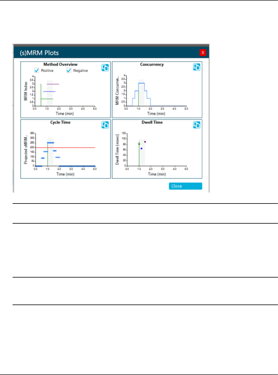
8. Click sMRM Summary to view a graphical representation of the sMRM method. Click Close
to close it.
Figure 5-5 (s)MRM Plots Dialog
Note: Multiple (s)MRM Plots dialogs can be open at the same time, one for each MS
method that is open in the MS Method workspace.
9. Do one of the following to save the MS method:
• Click Save > Save to save the method in the same project with the same name.
• Click Save > Save As to save the method with a new name or in a different project.
• Click Save > Lock Method to lock the method if it is ready for routine analysis.
Note: Lock the method to prevent unauthorized users from editing it. Only users with the
Lock/Unlock methods permission can edit locked methods. Other users can only submit
them.
The Save As MS Method dialog opens.
10. Type a name in the File Name field.
11. Click Save.
12. Run the MS method with appropriate LC method, and adjust the parameters to optimize
performance. Refer to the section: Run an MS Method Manually.
Operating Instructions—Acquisition
SCIEX OS Software for SCIEX Triple Quad and QTRAP
Systems
50/262
Software User Guide
RUO-IDV-05-9804-F

Create an stMRM Algorithm Method
Prerequisite Procedures
• Create an MS method that contains an MRM experiment. Refer to the following procedures:
• Create an MS Method
• Create an MRM Method Using Guided MRM
Note: Echo
®
MS systems: The Scout Triggered MRM (stMRM) algorithm is not supported.
1. Open an MS method that contains an MRM experiment by following these steps:
a. Click Open.
b. Select the MS method.
c. Click Open.
2. In the MRM Mode field, select Scout triggered MRM RT or Scout triggered MRM Group
The Scout Triggered MRM (stMRM) algorithm fields are shown.
3. Set Target Cycle Time to a value appropriate for the peak width.
4. In the Mass Table, for each marker transition, select the Trigger check box and specify the
Trigger threshold.
5. Scout triggered MRM RT mode: Specify retention times that indicate the elution order and
then set an RT overlap. Refer to the section: Retention Time Mode.
6. Scout triggered MRM Group mode: Assign each transition to a super group. The marker
transition and all of its dependent transitions must be in the same super group. Refer to the
section: Group Mode.
7. (Optional) Update the advanced parameters by following these steps:
a. Click Advanced > Show advanced parameters.
b. Adjust Minimum Dwell Time, Maximum Dwell Time, Settling time, and Pause time,
as required.
c. (Optional) In the mass table, adjust Q1 resolution or Q3 resolution, or both.
8. Click sMRM Summary to view a graphical representation of the sMRM method. Click Close
to close it.
Operating Instructions—Acquisition
Software User Guide
RUO-IDV-05-9804-F
SCIEX OS Software for SCIEX Triple Quad and QTRAP
Systems
51/262
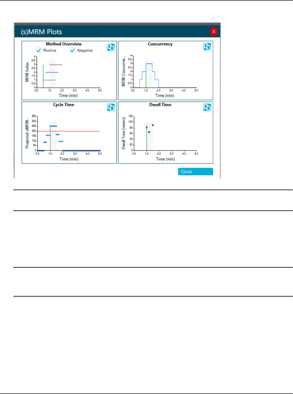
Figure 5-6 (s)MRM Plots Dialog
Note: Multiple (s)MRM Plots dialogs can be open at the same time, one for each MS
method that is open in the MS Method workspace.
9. Do one of the following to save the MS method:
• Click Save > Save to save the method in the same project with the same name.
• Click Save > Save As to save the method with a new name or in a different project.
• Click Save > Lock Method to lock the method if it is ready for routine analysis.
Note: Lock the method to prevent unauthorized users from editing it. Only users with the
Lock/Unlock methods permission can edit locked methods. Other users can only submit
them.
The Save As MS Method dialog opens.
10. Type a name in the File Name field.
11. Click Save.
12. Run the MS method with appropriate LC method, and adjust the parameters to optimize
performance. Refer to the section: Run an MS Method Manually.
Operating Instructions—Acquisition
SCIEX OS Software for SCIEX Triple Quad and QTRAP
Systems
52/262
Software User Guide
RUO-IDV-05-9804-F

Create a Method with Multiple Experiments
Prerequisite Procedures
• Create an MS method. Refer to the following procedures:
• Create an MS Method
• Create an MRM Method Using Guided MRM
1. Open the MS method to which an experiment will be added by following these steps:
a. Click Open.
b. Select the MS method.
c. Click Open.
2. In the Method Overview pane, click Add Experiment, and then the scan type of the
experiment to be added.
Figure 5-7 Add Experiment Menu
Operating Instructions—Acquisition
Software User Guide
RUO-IDV-05-9804-F
SCIEX OS Software for SCIEX Triple Quad and QTRAP
Systems
53/262

3. Set the experiment parameters. For a description of the parameters, refer to the document:
Help System.
4. Repeat step 2 and step 3 for each experiment to be added.
5. (Optional) Click Options > Apply experiment scheduling to configure a Start run time
and Stop run time for each experiment.
Note: Experiment scheduling is not available for Scheduled MRM (sMRM) and Scout
Triggered MRM (stMRM) algorithm experiments. Therefore, the following restrictions apply:
• If experiment scheduling is applied to multiple MRM experiments, then they cannot be
converted to sMRM or stMRM experiments. Nor can sMRM or stMRM experiments be
added to an MRM method with the experiment scheduling feature enabled.
• Experiment scheduling cannot be applied to an MS Method that contains sMRM or
stMRM experiments.
6. Do one of the following to save the MS method:
• Click Save > Save to save the method in the same project with the same name.
• Click Save > Save As to save the method with a new name or in a different project.
• Click Save > Lock Method to lock the method if it is ready for routine analysis.
Note: Lock the method to prevent unauthorized users from editing it. Only users with the
Lock/Unlock methods permission can edit locked methods. Other users can only submit
them.
The Save As MS Method dialog opens.
7. Type a name in the File Name field.
8. Click Save.
For scan types other than MRM scan types, optimizing the MS method requires the manual,
iterative adjusting of parameters, acquiring data, and then observing the effect of the
adjustment on the signal.
Open an MS Method
Use this procedure to open an MS method created with SCIEX OS. To open methods created
with the Analyst software, refer to the section: Convert an Analyst Software Method.
SCIEX OS can open an MS method created for a mass spectrometer that is different than the
active mass spectrometer. For example, it can convert a method created for a SCIEX Triple
Quad 5500+ system for use with a SCIEX Triple Quad 4500 system. To do so, make sure that
the MS method is in the current project. While opening the MS method, the software adjusts the
parameters to be compatible with the active device.
Operating Instructions—Acquisition
SCIEX OS Software for SCIEX Triple Quad and QTRAP
Systems
54/262
Software User Guide
RUO-IDV-05-9804-F

Note: The software cannot convert a method created for a X500 QTOF or ZenoTOF system for
use with SCIEX Triple Quad or QTRAP systems.
1. Open the MS Method workspace.
2. Click Open.
The Open MS Method dialog opens. It contains the list of MS methods in the current project.
3. (Optional) If the method to be opened is not in the current project, then select the project
that contains the method to be opened.
4. Select the MS method to open, and then click Open.
Tip! To select multiple methods, use the Shift or Ctrl key.
If the device in the MS method does not match the active device, then the Convert MS
Method dialog opens. Click OK to convert the MS method for the active device. After the
conversion is complete, click OK. Review the MS method carefully before using it.
Note: If the MS method is being converted from a different mass spectrometer, then the MS
method name is Untitled.
Convert an Analyst Software Method
MS methods created in the Analyst software can be converted for use in SCIEX OS. If the
device in the Analyst software method does not match the active device in SCIEX OS, then the
method parameters are adjusted to be compatible with the active device.
Note: SCIEX OS cannot open methods created for QTRAP systems.
Note: Make sure that the correct project name is selected in the status panel.
1. Open the MS Method workspace.
2. Click Open > Convert file.
3. Browse to and select the method to be converted, and then click Open.
The software converts the method, reporting any issues resulting from differences in the
devices and method file format. The method opens in the MS Method workspace.
4. Review the MS method and correct any issues.
5. Do one of the following to save the MS method:
• Click Save > Save to save the method in the same project with the same name.
• Click Save > Save As to save the method with a new name or in a different project.
• Click Save > Lock Method to lock the method if it is ready for routine analysis.
Operating Instructions—Acquisition
Software User Guide
RUO-IDV-05-9804-F
SCIEX OS Software for SCIEX Triple Quad and QTRAP
Systems
55/262

Note: Lock the method to prevent unauthorized users from editing it. Only users with the
Lock/Unlock methods permission can edit locked methods. Other users can only submit
them.
The Save As MS Method dialog opens.
6. Type a name in the File Name field.
7. Click Save.
For scan types other than MRM, optimizing the MS method involves manual, iterative
adjustment of parameters, acquisition of data, and then observation of the effect of the
adjustment on the signal.
Run an MS Method Manually
Prerequisite Procedures
• In the MS Method workspace, create an MS method or open an existing method. Refer to
the section: MS Method Workspace or Open an MS Method.
Use this procedure to run the active method in the MS Method workspace.
1. Click the down arrow on the Start button in the Data Acquisition panel and then click one of
the following:
• Start: This option runs the MS method without an LC.
• Start with LC
Note: This option is not available for Echo
®
MS systems.
Refer to the section: Data Acquisition Panel.
WARNING! Fire Hazard. Do not direct more than 3 mL/min of solvent in the ion
source. Although the LC components can provide a flow rate up to 5 mL/min,
directing more than 3 mL/min of solvent could result in solvent accumulating
in the ion source. Flow can be split with a tee to make sure that the maximum
flow rate provided to the ion source does not exceed 3 mL/min.
If the user clicks Start with LC, then the Start with LC dialog opens. For information about
the fields on this dialog, refer to the document: Help System.
Note: The LC system must be activated and an LC method must have been created and
saved.
Operating Instructions—Acquisition
SCIEX OS Software for SCIEX Triple Quad and QTRAP
Systems
56/262
Software User Guide
RUO-IDV-05-9804-F

Figure 5-8 Start with LC Dialog
2. (Optional) To view the data in the Explorer workspace, click Open data exploration to view
real-time data (
) in the Data Acquisition panel.
Real-time acquisition is indicated in the Explore pane by the words Acquiring, Finished, or
Aborted in the sample title.
Figure 5-9 Real-time Acquisition—Acquiring
3. (Optional) Optimize the MS parameters, as required. For a description of the parameters,
refer to the document: Help System.
4. Click Stop in the Data Acquisition panel.
5. (Optional) To save the data, follow these steps:
a. Click Save to save the data.
The Save Data dialog opens.
b. (Optional) Select the project and subfolder, if applicable, in which to save the data.
c. Type a name in the File Name field.
Operating Instructions—Acquisition
Software User Guide
RUO-IDV-05-9804-F
SCIEX OS Software for SCIEX Triple Quad and QTRAP
Systems
57/262

d. Click Save.
6. Do one of the following to save the MS method:
• Click Save > Save to save the method in the same project with the same name.
• Click Save > Save As to save the method with a new name or in a different project.
• Click Save > Lock Method to lock the method if it is ready for routine analysis.
Note: Lock the method to prevent unauthorized users from editing it. Only users with the
Lock/Unlock methods permission can edit locked methods. Other users can only submit
them.
The Save As MS Method dialog opens.
7. Type a name in the File Name field.
8. Click Save.
Work With Default Settings
Use this procedure to set the default method parameters. Default values for source and gas
parameters apply to all of the experiment types. Default values for compound dependent
parameters are defined for each experiment type. Default parameters are set for each polarity.
The changes are not applied to existing methods. Any methods created after the changes are
made will have the new values.
1. Open the MS Method workspace.
2. Click Advanced > Default settings.
The Source and Gas Settings page is shown.
3. Select a Polarity.
4. Set the source and gas parameters.For a description of the parameters, refer to the
document: Help System.
Note: For Negative polarity, only the Spray voltage can be adjusted. The other source and
gas parameter values are taken from the Positive polarity.
5. Click Save.
6. Click Compound Dependent Settings.
The Compound Dependent Settings page is shown.
7. Select the Experiment type.
8. Select a Polarity.
9. Set the parameters for the selected experiment type. For a description of the parameters,
refer to the document: Help System.
Operating Instructions—Acquisition
SCIEX OS Software for SCIEX Triple Quad and QTRAP
Systems
58/262
Software User Guide
RUO-IDV-05-9804-F

10. Click Save.
LC Method Workspace
Use this workspace to create and manage LC methods.
Multiple methods can be open in the LC Method workspace. Using the Views menu, the user
can change the arrangement of the method windows to tabbed, vertical tiled, horizontal tiled,
or floating views. In floating view, windows can be resized, maximized, or minimized, moved
outside of the SCIEX OS window, and moved to a different monitor.
The title bar of the method window contains the method and project names. In the tiled and
floating views, the title bar of the active method is blue and the title bars of the other methods
are gray. In the tabbed view, the tab for the active method is white, and the tabs for the other
methods are blue.
Access to features in this workspace is controlled by the role assigned to the user. Refer to the
document: Laboratory Director Guide.
Create an LC Method
Refer to the documentation that comes with the LC device.
1. Open the LC Method workspace.
2. Click New.
3. Click a device in the left panel and then edit the fields, as required.
4. Save and optionally lock the LC method by clicking one of the following commands:
• Save: To save the LC method.
• Save > Lock Method: To save and lock the LC method.
The Save As LC Method dialog opens.
5. Type a name for the LC method in the File Name field, and then click Save.
AE Method Workspace
Use this workspace to create and manage AE methods. When an Echo
®
MS system is
activated, the LC Method tile on the Home page changes to AE Method.
Access to features in this workspace is controlled by the role assigned to the user. Refer to the
document: Laboratory Director Guide.
Create an AE Method
Note: Make sure that the correct project name is selected in the status panel.
Operating Instructions—Acquisition
Software User Guide
RUO-IDV-05-9804-F
SCIEX OS Software for SCIEX Triple Quad and QTRAP
Systems
59/262

1. Open the AE Method workspace.
2. Click New.
3. Edit the fields, as required. For a description of the parameters, refer to the document: Help
System.
4. Save and optionally lock the AE method by clicking one of the following commands:
• Save: To save the AE method.
• Save > Lock Method: To save and lock the AE method.
The Save As AE Method dialog opens.
5. Type a name for the AE method in the File Name field, and then click Save.
Batch Workspace
The Batch workspace contains information about a set of samples to be acquired and, optionally,
processed. Batches tell the software the order in which to acquire and process the samples.
Access to features in this workspace is controlled by the role assigned to the user. Refer to the
document: Laboratory Director Guide.
Note: For the selected autosampler, the rack type, rack position, plate type, plate position, and
vial position are all dependent on each other and only certain values are valid.
Note: When used with the Echo
®
MS system, this workspace defines how the samples are
arranged in the well plates. The system optimizes the sequence of acquisition for throughput.
Table 5-1 Batch Workspace Columns
Column Name Definition Field Value Requirements
Sample and method information ( )
Sample Name Name of the sample. Less than 252 characters.
Sample ID A custom number or other
identifier for the sample.
Less than 252 characters. The
Sample ID field cannot contain
any of these invalid characters:
\ / : ; * ? " < > |=
Barcode ID
Unique ID from a sample. Less than 250 characters.
MS Method Name of the method. The MS method must exist in the
current project. The field is not
case-sensitive.
Operating Instructions—Acquisition
SCIEX OS Software for SCIEX Triple Quad and QTRAP
Systems
60/262
Software User Guide
RUO-IDV-05-9804-F

Table 5-1 Batch Workspace Columns (continued)
Column Name Definition Field Value Requirements
LC Method (For all systems except Echo
®
MS systems) Name of the liquid
chromatography method.
The LC method must exist in the
current project. The field is not
case-sensitive.
AE Method (Echo
®
MS systems) Name of the
acoustic ejection method.
Shown when the Echo
®
MS
system is active on the Devices
page.
The AE method must exist in the
current project. The field is not
case-sensitive.
Rack Type The rack type for the autosampler. Must be one of the valid choices
for the autosampler specified in
the LC method.
Rack Position The position of the rack on the
tray.
Numerical value.
Plate Type The type of well-plate in the
autosampler.
Note: This column is unavailable if
the Rack Type describes vials.
Must be one of the valid choices
for the autosampler specified in
the LC method.
Plate Position The position of the plate on the
rack.
Must match one of the predefined
autosampler plate positions.
Vial Position (LC methods) The position of the
vial in a rack or on a plate.
Numerical value. The largest value
must not be larger than the
number of vials in the rack.
Well Position (AE methods) The position of the
well on a plate.
Shown when the Echo
®
MS is
active on the Devices page.
Numerical value. The largest value
must not be larger than the
number of wells in the rack.
Operating Instructions—Acquisition
Software User Guide
RUO-IDV-05-9804-F
SCIEX OS Software for SCIEX Triple Quad and QTRAP
Systems
61/262

Table 5-1 Batch Workspace Columns (continued)
Column Name Definition Field Value Requirements
Injection Volume
(µL)
The amount of sample to be
injected.
Note:
For LC methods only, the injection
volume is taken from the LC
method. The user can override
this injection volume in the Batch
workspace or in the imported
batch file. When the batch is
submitted, the injection volume
is validated against the range
supported by the LC device.
To revert to the injection volume
specified in the LC method, delete
the contents of this field, and then
select the LC method again in the
LC Method field.
Numerical value.
Sample Type The type of sample. Make sure that the sample type
matches one of the predefined
sample types. Any type that
does not match is automatically
replaced with Unknown.
Dilution Factor
The dilution factor for individual
samples.
For SCIEX-developed methods,
the value must be 1.000000.
Must be a value greater than zero
and with six decimal places. The
default value is 1.000000. Do not
leave the field blank.
Operating Instructions—Acquisition
SCIEX OS Software for SCIEX Triple Quad and QTRAP
Systems
62/262
Software User Guide
RUO-IDV-05-9804-F

Table 5-1 Batch Workspace Columns (continued)
Column Name Definition Field Value Requirements
Data File The name of the file to which the
acquired data is saved. Include
the full path to the subfolder in
which the file will be stored.
Must be less than 252 characters.
The total number of characters
includes the number of characters
in the data subfolder path. The
data file cannot contain any of
these invalid characters: \ / : ; * ?
" < > |=
Tip! Click the arrow to select a
subfolder from the list or type the
name of a new subfolder. Make
sure to include a backslash (\)
between the subfolder and file
name. If the subfolder does not
exist, then it will be created when
the batch runs.
Note: (Echo
®
MS systems) Do not
use the same data file name in
multiple batches.
Processing Method Name of the method. If an existing
Results File will be used, then
leave this field blank. When an
existing Results File is selected,
the value *Embedded Method* is
automatically shown in this field.
Note: The processing method
must be compatible with the MS
method specified for the sample.
Select a processing method from
the list of processing methods in
the project.
Operating Instructions—Acquisition
Software User Guide
RUO-IDV-05-9804-F
SCIEX OS Software for SCIEX Triple Quad and QTRAP
Systems
63/262

Table 5-1 Batch Workspace Columns (continued)
Column Name Definition Field Value Requirements
Results File The name of the file to which
the processed results are saved.
If a valid Results File is
specified, then the sample data
will be processed automatically
after acquisition is complete. If
the file name is invalid, then the
batch submission process cannot
be completed.
Note: If an existing Results File
is selected, then the embedded
method for the selected Results
file is used for processing, and the
text in the Processing Method
cell is replaced with *Embedded
Method*.
The file name cannot contain any
of these invalid characters: \ / ; :
* ? " < > |=
The file path, including the file
name and subfolders, must be
less than 252 characters.
Tip! Click the arrow to select an
existing Results File from the list.
To create a file, type the file name.
The file will be created when the
first sample in the submitted batch
is processed.
Note: (Echo
®
MS systems) Do not
use the same results file name in
multiple batches.
Marker Well The well used to align the timing
file with the first well. The Marker
Well must contain at least one
of the components defined in the
MS method specified in the MS
Method column.
Shown when the Echo
®
MS is
active on the Devices page.
Select True for the marker well.
All other wells are automatically
set to False when the batch is
submitted.
Comment
Text Must be less than 50 characters.
The Comment field cannot
contain any of these invalid
characters: \ / : ; * ? " < > |=
Custom columns
(Optional) User-defined columns,
in text, integer, or real number
format.
Requirements depend on the
format.
Component Concentrations ( )
Operating Instructions—Acquisition
SCIEX OS Software for SCIEX Triple Quad and QTRAP
Systems
64/262
Software User Guide
RUO-IDV-05-9804-F

Table 5-1 Batch Workspace Columns (continued)
Column Name Definition Field Value Requirements
Component The name of a component defined
in the MS method, processing
method or Results Table.
The batch can contain up to 4,000
component rows.
Component names are taken
from the MS method, for MRM
scans, the processing method, or
the Results Table. The name is
validated during method creation.
Components can also be added
to the table manually. Refer to
the section: Add a Component
Concentration.
Note: If the import file contains a
data column that does not match
any of the columns in the batch
grid, then the column is treated as
a Compound or Component Name
column. A concentration column is
added and it is populated with the
values from this data column.
Component
concentration
Analyte or internal standard
concentration for standard and QC
sample types. The table contains
a column for each sample. The
sample name is used as the
column name.
Numerical value greater than or
equal to zero.
Manage the Batch
Note: Make sure that the correct project name is selected in the status panel.
In the Batch workspace, use the following features to manage the batch.
Table 5-2 Batch Workspace Features
To Do This Do This
Show or hide columns Click View. Refer to the section: Show or Hide Columns.
Cut rows Click Manage Samples > Cut.
Copy rows Click Manage Samples > Copy.
Paste rows Click Manage Samples > Paste.
Operating Instructions—Acquisition
Software User Guide
RUO-IDV-05-9804-F
SCIEX OS Software for SCIEX Triple Quad and QTRAP
Systems
65/262

Table 5-2 Batch Workspace Features (continued)
To Do This Do This
Insert a row Click Manage Samples > Insert sample.
Delete a row Click Manage Samples > Delete sample.
Select columns Click View. Refer to the section: Show or Hide Columns.
Add a subfolders to a project Click Manage Samples > Add data sub-folders. Refer to the
document: Help System.
Print the batch Click Print.
Save the batch to the current
project
Click Save > Save or Save > Save As.
Export the batch as a txt or
csv file
Click Save > Export.
Show or Hide Columns
1. Open the Batch workspace.
2. Click View.
3. Select or clear the column check boxes, as required, in the View dialog. For descriptions of
the columns, refer to the table: Table 5-1.
Operating Instructions—Acquisition
SCIEX OS Software for SCIEX Triple Quad and QTRAP
Systems
66/262
Software User Guide
RUO-IDV-05-9804-F

Figure 5-10 View Dialog
4. Click OK.
Add a Custom Column
Use this procedure to add columns to the batch to store extra information about the sample,
such as dry weight, so that it can be used in processing, for example, in formulas and calculated
columns.
1. Open the Batch workspace.
2. Right-click in the batch grid, and then click Add Custom Column.
The Add Custom Column dialog opens.
3. In the Column name field, type a name for the column.
The name must be unique. It cannot be the same as the name of any predefined column.
Operating Instructions—Acquisition
Software User Guide
RUO-IDV-05-9804-F
SCIEX OS Software for SCIEX Triple Quad and QTRAP
Systems
67/262

4. In the Column type field, select one of these types:
• Integer: The column contains whole numbers. Decimal values will be rounded to the
nearest whole number.
• Real: The column contains real numbers, up to six decimal places.
• Text: The column contains text, up to 128 characters.
5. Click Add.
The new column is added at the right of the Batch workspace.
Change the Name of a Custom Column
Note: The Column type cannot be changed.
1. Open the Batch workspace.
2. Right-click in the column to be changed, and then click Edit Custom Column.
The Edit Custom Column dialog opens.
3. In the Name field, type the new name for the column.
The name must be unique. It cannot be the same as the name of any predefined column.
4. Click Apply.
Remove Custom Columns
1. Open the Batch workspace.
2. Right-click in the batch grid, and then click Delete Custom Column.
The Delete Custom Column dialog opens.
3. Select the check box beside the names of the columns to be deleted.
4. Click Delete.
Operating Instructions—Acquisition
SCIEX OS Software for SCIEX Triple Quad and QTRAP
Systems
68/262
Software User Guide
RUO-IDV-05-9804-F

Import a Batch from a File
Prerequisite Procedures
• Create a batch file. For a description of the fields to be included in the file, refer to the table:
Table 5-1.
Note: In the Microsoft Excel file being imported, the predefined columns must be first,
followed by the custom columns. The column headers for the predefined columns must
match the column names in SCIEX OS. If the column headers for the predefined columns
are not correct, then the information will not be imported. Only a period is supported as a
decimal separator in csv or xsl files.
Note: Close the batch file before importing it. The batch file cannot be imported if it is open
in Microsoft Excel.
• (Optional for import from a Watson LIMS) To automatically populate the LC Method field,
make sure that the name of the LC method is the same as the name of the MS method.
Note: The Watson LIMS does not have an LC method field. If the name of the LC method
is not the same as the name of the MS method, then the LC method column must be
populated manually.
Review the batch contents before submitting the samples.
Tip! To access the cut, copy, paste, add rows, and remove rows features, click Manage
Samples.
1. Open the Batch workspace.
2. (Optional) Click View to select the columns that will be shown in the Batch workspace.
3. Click Open > Import from file.
The Batch Import dialog opens.
4. Click Browse.
5. Navigate to the required file.
6. Click Open.
7. (Optional) Select or clear the Append to current batch check box, as required.
Note: Any existing data in the grid is overwritten if the user does not select the Append to
current batch option.
8. Click Import.
Operating Instructions—Acquisition
Software User Guide
RUO-IDV-05-9804-F
SCIEX OS Software for SCIEX Triple Quad and QTRAP
Systems
69/262

9. (Optional) To use the plate layout as a reference for selecting or confirming a sample
location, click Plate Layout.
The plate layout automatically provides well and vial positions for unassigned samples.
10. Make sure that the column oven temperature is reached before submitting the batch.
11. Save the batch:
a. Click Save As.
The Save As Batch dialog opens.
b. Type a File Name and then click Save.
12. Submit the batch. Refer to the section: Submit a Batch.
Import a Batch from a LIMS
Prerequisite Procedures
• Configure the LIMS in the Configuration workspace. Refer to the document: Help System.
Note: To import a batch from a Watson LIMS, refer to the section: Import a Batch from a File.
1. Open the Batch workspace.
2. (Optional) Click View to select the columns that will be shown in the Batch workspace.
3. Click Open > Import from LIMS.
The Import a Batch File dialog opens.
4. Type the file location or file name.
5. Type the batch identifier in the Batch Identifier field.
6. (Optional) Select or clear the Append to current batch check box, as required.
Note: Any existing data in the grid is overwritten if the user does not select the Append to
current batch option.
7. Click Import.
8. (Optional) To use the plate layout as a reference for selecting or confirming a sample
location, click Plate Layout.
The plate layout automatically provides well and vial positions for unassigned samples.
9. Make sure that the column oven temperature is reached before submitting the batch.
10. Save the batch:
a. Click Save As.
The Save As Batch dialog opens.
Operating Instructions—Acquisition
SCIEX OS Software for SCIEX Triple Quad and QTRAP
Systems
70/262
Software User Guide
RUO-IDV-05-9804-F

b. Type a File Name and then click Save.
11. Submit the batch. Refer to the section: Submit a Batch.
Create a Batch Manually
Review the batch contents before submitting the samples.
Note: If the mass spectrometer is using contact closure to communicate with an external device,
then follow these guidelines:
• Make sure that the sample sequence defined in the batch matches the sequence defined on
the external device.
• Make sure that the method duration is less than or equal to the interval between injections, as
defined on the external device.
Tip! To access the cut, copy, paste, add rows, and remove rows features, click Manage
Samples.
1. Open the Batch workspace.
2. (Optional) Click View to select the columns that will be shown in the Batch workspace.
Tip! To use an existing batch, click Open > Open.
3. Click New.
4. (Optional) To use the plate layout as a reference for selecting or confirming a sample
location, click Plate Layout.
The plate layout automatically provides well and vial positions for unassigned samples.
5. Type the batch information in the grid.
For a description of the columns in the grid, refer to the table: Table 5-1.
Operating Instructions—Acquisition
Software User Guide
RUO-IDV-05-9804-F
SCIEX OS Software for SCIEX Triple Quad and QTRAP
Systems
71/262

Tip! The Batch workspace provides the following features to make creating batches easier:
• The content for some cells, such as the Sample Type cell, can be selected from a list in
the cell. Click the right side of the cell to show the list.
• The second and subsequent rows added to a batch automatically populate with the
values from the preceding row.
• The user can copy a single cell by selecting the cell, clicking the bottom right corner of
the cell, and then dragging to the last row to which the cell content is to be copied.
• The user can copy a group of cells in the same row by selecting the cells, clicking the
bottom corner of the right-most cell, and then dragging to the last row to which the cell
content is to be copied.
• The user can copy a series of values by typing sequential values in two rows, selecting
both cells, clicking the bottom right corner of the bottom cell, and dragging to the last row
in the series.
• The user can use the Copy (Ctrl+C) and Paste (Ctrl+V) commands to copy the content
of a cell or group of cells and then paste them in a new location.
Note: LC columns are not available until an LC method is selected.
Tip! To configure the batch to process the sample automatically after it is acquired, use one
of the following methods:
• To use an embedded processing method, select an existing Results File. The sample
will be processed with the embedded method of the corresponding Results file.
• To use a new processing method, clear the Results File field. When the Results File
field is cleared, the Processing Method field becomes available. Select a Processing
Method and then type a new Results File name. The sample will be processed with the
selected processing method.
When processing in the non-targeted screening workflow, a comparison sample cannot
be selected for automatic processing. For processing methods that use the AutoPeak
algorithm, the software always builds the integration model with the samples used to create
the method.
6. (Optional) Define component concentrations. Refer to the section: Add a Component
Concentration
7. (Optional) To apply decision rules to the batch, follow these steps:
a. Select the Decision Rules check box.
b. Click Decision Rules and then select Apply for each decision rule to be applied to the
batch. To add decision rules, refer to the section: Add a Decision Rule.
Operating Instructions—Acquisition
SCIEX OS Software for SCIEX Triple Quad and QTRAP
Systems
72/262
Software User Guide
RUO-IDV-05-9804-F

c. Click Save.
Note: If the Decision Rules option is selected and at least one decision rule is active
for a batch, then Decision Rules: Active is shown beside the batch name in the Queue
workspace. If the active project is located on the network and the network is unavailable,
then the text is Decision Rules: Disabled is shown.
8. Save the batch:
a. Click Save As.
The Save As Batch dialog opens.
b. Type a File Name and then click Save.
9. Make sure that the column oven temperature is reached before submitting the batch.
10. Make sure that the system has been equilibrated with the MS and LC method that is used in
the batch.
11. Submit the batch. Refer to the section: Submit a Batch.
Use the Plate Layout Feature to Create a Batch (LC System)
The plate layout feature provides a graphical representation of the rack and plate structures that
can be used to populate the grid in the Batch workspace.
1. Open the Batch workspace.
2. Select an MS Method.
3. Select an LC Method.
The LC system must be active.
4. Type the name of the Data File in which the acquired data will be saved.
5. Select the Processing Method that will be used to process the data after it is acquired.
6. Type the name of the Results File in which the processed data will be saved.
7. Click Plate Layout.
The Plate Layout window opens and, by default, shows a graphical representation of the
plate.
8. Set the properties for the plate.
The window updates to show a graphical representation of the selected plate type.
9. On the graphical representation, click a sample position.
The selected sample position is fully highlighted in the graphical representation. The Batch
workspace is updated, starting with the first row that does not have the sample position
defined completely, that is, a row that does not include the Rack Type, Plate Type, if wells
are used, and Vial Position values. The grid shows the sample positions accordingly.
Operating Instructions—Acquisition
Software User Guide
RUO-IDV-05-9804-F
SCIEX OS Software for SCIEX Triple Quad and QTRAP
Systems
73/262

10. Continue to click sample positions as needed in the graphical representation to populate the
grid in the Batch workspace.
If sample positions are typed in the grid in the Batch workspace, then the graphical
representation is updated accordingly.
Tip! To remove all of the data associated with a specified rack type, click Clear All. If the
selected rack type identifies a plate, then the menu under Clear All includes Clear Front
and Clear Back.
11. To specify a replicate selected sample position, click the sample position in the graphical
representation.
The graphical representation of the plate layout shows the replicate sample position with a
colored outline and the grid in the Batch workspace shows the data accordingly.
Figure 5-11 Plate Layout—Replicate Sample Position (Position 1)
Note: Unselected positions are shown in gray, and positions that have been selected once
are shown in blue with a gray border.
12. To see the sample index in the graphical representation, hover the cursor over the
highlighted sample position.
A tooltip shows the sample index.
13. When all of the positions are assigned and reviewed, click Close in the Plate Layout window
and then click Save in the Batch workspace.
Use the Plate Layout Feature to Create a Batch (Echo
®
MS
System)
The plate layout feature provides a graphical representation of the sample wellplates that can be
used to populate the grid in the Batch workspace.
1. Open the Batch workspace.
2. Complete the first row of the batch grid:
Operating Instructions—Acquisition
SCIEX OS Software for SCIEX Triple Quad and QTRAP
Systems
74/262
Software User Guide
RUO-IDV-05-9804-F

a. Select an MS Method.
b. Select an AE Method.
c. Type the name of the Data File in which the acquired data will be saved.
d. Select the Processing Method that will be used to process the data after it is acquired.
e. Type the name of the Results File in which the processed data will be saved.
3. Click Plate Layout.
The Plate Layout window opens and, by default, shows a graphical representation of the
well plate. Subsequently, the window shows the plate type that was last used or the plate
type specified for a currently highlighted sample.
4. Select the Plate Type.
The window updates to show a graphical representation of the selected plate type.
5. For Sequence field, click the icon representing the order in which samples are arranged on
the plate. Options include the following:
• Z-Seq (Z-Sequence): Samples are arranged from left to right in the first row, then left to
right in the second row, and so on.
• N-Seq (N-Sequence): Samples are arranged from top to bottom in the first column, then
top to bottom in the second column, and so on.
• R-Ser-Seq (Row-Serpentine-Sequence): Samples are arranged from left to right in the
first row, then right to left in the second row, then left to right in the third row, and so on.
• C-Ser-Seq (Column-Serpentine-Sequence): Samples are arranged from top to bottom in
the first column, then bottom to top in the second column, and then top to bottom in the
third column, and so on.
6. On the graphical representation, click the sample positions to be added to the batch, select
the sequence and then click Add Selected.
Tip! To add all samples, click Select All. To clear all selections, click Remove All.
Tip! Drag across multiple wells to select them.
The selected samples are added to the grid in the Batch workspace.
7. Click Close.
8. Complete the remaining fields in the batch grid.
9. (Optional) Save the batch.
10. Submit the batch. Refer to the section: Submit a Batch.
Operating Instructions—Acquisition
Software User Guide
RUO-IDV-05-9804-F
SCIEX OS Software for SCIEX Triple Quad and QTRAP
Systems
75/262

Manage Component Concentrations
Add a Component Concentration
The batch contains component concentrations defined in the MS method, processing method, or
Results Table. Use this procedure to add additional component concentrations.
Note: Component concentrations added using this procedure are editable for samples of type
QualityControl and Standard. Component concentrations are also added to a batch when
a processing method that contains components is defined for a sample. The component
concentrations added by the processing method are only editable for samples with processing
methods that contain the component.
1. In the Batch workspace, click Component Concentrations ( ).
2. Click Manage Components > Add Component.
3. Type the name of the Component.
4. Click OK.
The new component concentration is added to the current batch.
Delete a Component Concentration
Use this procedure to remove a component concentration from the batch.
1. In the Batch workspace, click Component Concentrations ( ).
2. Click Manage Components > Remove Component.
A list of components is shown. It contains all components added with the Add Component
Concentration command, or when a MRM method or processing method was added to the
batch.
3. Select the component from the list.
4. Click OK.
Manage Decision Rules
Add a Decision Rule
Use this procedure to add a decision rule.
1. In the Batch workspace, click Decision Rules.
The Decision Rules dialog opens.
2. Click Add Rule.
The Decision Rule Configuration dialog opens.
3. Type a name for the decision rule.
Operating Instructions—Acquisition
SCIEX OS Software for SCIEX Triple Quad and QTRAP
Systems
76/262
Software User Guide
RUO-IDV-05-9804-F

4. Define the properties for the decision rule, including the flagging rule, when the decision rule
will be evaluated, and the response. Refer to the document: Help System.
5. Click Save to save the decision rule.
6. Click Save to close the dialog.
Note: If the user does not click Save on the Decision Rules dialog, then the new decision
rule is not saved.
Change a Decision Rule
1. In the Batch workspace, click Decision Rules.
The Decision Rules dialog opens.
2. Click the Decision Rule Name of the decision rule to be changed.
The Decision Rule Configuration dialog opens.
3. Change the Decision rule name and the settings for the decision rule, including the
flagging rule, when the decision rule will be evaluated, and the response. Refer to the
document: Help System.
4. Click Save to save the decision rule.
5. Click Save to close the dialog.
Note: If the user does not click Save on the Decision Rules dialog, then the new decision
rule is not saved.
Delete a Decision Rule
Use this procedure to delete a decision rule.
1. In the Batch workspace, click Decision Rules.
The Decision Rules dialog opens.
2. Click the Flagging Rule Used.
3. Click Delete Rule to delete the decision rule.
4. Click Save.
Create a Duplicate Rule
Use this procedure to create a duplicate rule.
1. In the Batch workspace, click Decision Rules.
The Decision Rules dialog opens.
2. Click the decision rule to be duplicated.
3. Click Duplicate Rule.
Operating Instructions—Acquisition
Software User Guide
RUO-IDV-05-9804-F
SCIEX OS Software for SCIEX Triple Quad and QTRAP
Systems
77/262

4. Click Save.
Import Decision Rules
Use this procedure to import decision rules.
1. In the Batch workspace, click Decision Rules.
The Decision Rules dialog opens.
2. Click Import List.
3. Navigate to and select the text file to be imported, and then click Open.
4. Click Save.
Export Decision Rules
1. In the Batch workspace, click Decision Rules.
The Decision Rules dialog opens.
2. Click Export List.
3. Navigate to the folder where the text file will be saved, type a file name, and then click Save.
4. Click Cancel.
Equilibrate the System
Equilibrate the system at the start of the day, before a new method is run, or before submitting a
batch. Equilibration warms up and prepares the mass spectrometer and LC system or the Echo
®
MS system for the next sample or batch.
1. Click Equilibrate on the status panel.
The Equilibrate dialog opens.
2. Select an MS Method from the MS Method list.
3. Do one of the following:
• Select an LC method from the LC Method list.
• Select an AE method from the AE Method list.
4. Type the equilibration time in the Time (min) field, in minutes.
(Echo
®
MS systems) A minimum of 10 minutes equilibration time is recommended.
5. Click OK.
When equilibration is complete, the system status in the status panel is Ready.
Tip! Open the Queue workspace to monitor the progress of the equilibration. The Queue
workspace indicates how much time is required for the equilibration to complete. To stop
equilibration before it finishes, click Stop in the Queue workspace.
Operating Instructions—Acquisition
SCIEX OS Software for SCIEX Triple Quad and QTRAP
Systems
78/262
Software User Guide
RUO-IDV-05-9804-F

Submit a Batch
Prerequisite Procedures
• Equilibrate the System.
• Open a batch in the Batch workspace.
1. Click Submit.
The Submit Samples dialog opens.
2. Click OK to continue.
If errors are shown at the top of the screen, resolve them, and then click Submit again. The
batch is not added to the queue until all of the errors are resolved.
Tip! If the queue is not started, navigate to the Queue workspace, and then click Start on
the menu bar.
Submit a Single Sample to the Queue from the Batch
Workspace
Prerequisite Procedures
• Equilibrate the System.
• Open a batch in the Batch workspace.
1. Select the row index number of the sample.
2. Click Submit.
The Submit Samples dialog opens.
3. Click OK to continue.
If errors are shown at the top of the screen, resolve them, and then click Submit again. The
batch is not added to the queue until all of the errors are resolved.
Tip! If the queue is not started, navigate to the Queue workspace, and then click Start on
the menu bar.
Operating Instructions—Acquisition
Software User Guide
RUO-IDV-05-9804-F
SCIEX OS Software for SCIEX Triple Quad and QTRAP
Systems
79/262

Submit Multiple Samples to the Queue from the Batch
Workspace
Prerequisite Procedures
• Equilibrate the System.
• Open a batch in the Batch workspace.
1. Do one of the following:
• Press Ctrl while clicking the sample row index number of each sample.
• Drag up or down the list of index numbers.
Note: Samples are submitted in the order that they are selected and not in the order that
they are shown in the batch.
2. Click Submit.
The Submit Samples dialog opens.
3. Click OK to continue.
If errors are shown at the top of the screen, resolve them, and then click Submit again. The
batch is not added to the queue until all of the errors are resolved.
Tip! If the queue is not started, navigate to the Queue workspace, and then click Start on
the menu bar.
Queue Workspace
The Queue workspace shows:
• Queue status
• Batch status
• Sample acquisition and processing status
In this workspace, the user can manage batches and samples in the queue.
By default, the samples are not shown in the queue. Sample information is collapsed under the
batch name. The batch status, the batch name, the number of samples in the batch, and the
time remaining to acquire the current batch are shown.
Note: When the Echo
®
MS system is being used, the Queue workspace only shows batch
information. Sample information is not available.
Operating Instructions—Acquisition
SCIEX OS Software for SCIEX Triple Quad and QTRAP
Systems
80/262
Software User Guide
RUO-IDV-05-9804-F

Access to features in this workspace is controlled by the role assigned to the user. Refer to the
document: Laboratory Director Guide.
Note: Data is acquired simultaneously to both a SCIEX OS wiff2 file and a wiff file that is
compatible with the Analyst software.
Note: Do not manually change the integrated diverter valve position during sample acquisition.
Figure 5-12 Queue Workspace
Table 5-3 Queue Workspace Columns
Label Description
Batch Name The name of the batch that was submitted to the queue, the number of
samples in the batch, and the decision rule processing status.
The queue contains a row for each batch. By default, the batch is
collapsed, but it can be expanded to show all of the samples in the
batch. For each sample, information is shown in the following columns.
Note: For batches with decision rule processing, the software delays
the acquisition of the next sample to allow processing of the current
sample to finish. If processing does not finish within the allowed time,
then decision rules are disabled. The delay time is 1.5 times the
acquisition time.
Acquisition Status The status of the data acquisition. For information on the status icons,
refer to the section: Queue Icons.
Est. Start Time The time that acquisition of this sample started.
Acquisition Time How long it took to acquire this sample.
Sample Name The name of the sample, as specified in the batch.
Sample ID The identifier for the sample, as specified in the batch.
Barcode The barcode number of the sample vial, as specified in the batch.
Rack Code The identifier for the LC rack, as specified in the batch.
Rack Position The installed location of the LC rack, as specified in the batch.
Operating Instructions—Acquisition
Software User Guide
RUO-IDV-05-9804-F
SCIEX OS Software for SCIEX Triple Quad and QTRAP
Systems
81/262

Table 5-3 Queue Workspace Columns (continued)
Label Description
Plate Code The identifier for the LC plate, as specified in the batch.
Plate Position The installed location of the LC plate, as specified in the batch.
Vial Position The location of the sample in the LC plate or rack.
MS Method The MS method, as specified in the batch.
LC Method The LC method, as specified in the batch.
Injection Volume The amount of sample injected.
Data File The name of the data file to which the data will be acquired.
Scanned Barcode The identifier for the vial.
User The name of the user who submitted the batch.
Project The project in which the data file will be saved.
Data File Status The status of the data file.
Auto Processing
Status
The status of the data processing. For information on the status icons,
refer to the section: Queue Icons.
Processing Method The processing method that will be used to process the acquired data.
If an existing Results file is being used, then this column contains the
text *Embedded Method*.
Results File The file to which the processed data will be written.
Decision Rule
Status
The flagging state of a sample and the action take by the decision rule.
Decision Rule
Summary
The name of the decision rule that is triggered.
Manage the Queue
Acquisition begins after the samples have been submitted from the Batch workspace. Make sure
that the system is equilibrated prior to submitting a batch. Refer to the section: Equilibrate the
System.
Note: Run the sample again if an abnormal termination occurs during sample acquisition. If the
abnormal termination is caused by a power failure, then the temperature of the autosampler tray
is not maintained and sample integrity might be compromised.
Use the features in the following table to manage the samples and batches in the queue.
Operating Instructions—Acquisition
SCIEX OS Software for SCIEX Triple Quad and QTRAP
Systems
82/262
Software User Guide
RUO-IDV-05-9804-F

Table 5-4 Queue Workspace Features
To Do This Do This
Show or hide columns. Click Manage > Display Columns. Refer to the section: Show
or Hide Columns.
View all of the samples in the
batch.
Click .
Collapse all of the samples in
the batch.
Click .
Start acquisition. Click Start. Equilibrate the system before running any
samples.
View the status of the
submitted samples.
Double-click the batch header.
Reacquire the selected
samples.
1. Click the samples.
2. Click Manage > Reacquire samples.
Delete the selected samples. 1. Click the samples.
2. Click Manage > Delete samples.
Delete all of the samples
below the selected sample.
1. Click the sample.
2. Click Manage > Delete samples below row selection.
Clear the queue of all of the
acquired batches or samples.
Click Manage > Clear queue.
Remove the focus from a
selected row.
Click Manage > Clear all selections.
Move the selected batch or
sample to the top of the
queue.
1. Click the batch header.
2. Click Manage > Move row to top.
Note: Only single batches or samples that have not been
acquired can be moved.
Move the selected sample up
in the queue.
1. Click the sample.
2. Click Manage > Move row up.
Note: Only single samples that have not been acquired can be
moved.
Operating Instructions—Acquisition
Software User Guide
RUO-IDV-05-9804-F
SCIEX OS Software for SCIEX Triple Quad and QTRAP
Systems
83/262

Table 5-4 Queue Workspace Features (continued)
To Do This Do This
Move the selected sample
down in the queue.
1. Click the sample.
2. Click Manage > Move row down.
Note: Only single samples that have not been acquired can be
moved.
Collapse all of the samples
and batches.
Click Manage > Collapse all rows.
Show all of the samples and
batches.
Click Manage > Expand all rows.
View data from a sample that
is in the process of being
acquired.
Do one of the following:
• Double-click the sample that is in the process of being
acquired.
Note: Double-click one of the columns to the left of the
Processing Status column.
• Click Open data exploration to view real time data ( )
in the Data Acquisition panel.
View data from a sample that
has been acquired.
Double-click the green check mark ( ) in the Acquisition
Status column.
View the Results file that was
created.
Double-click the green check mark ( ) in the Processing
Status column.
View the barcode vials that
are being scanned.
1. Click Manage > Display Columns.
2. Select the Barcode or Scanned Barcode check box, or
both, in the Select Columns dialog. Refer to the section:
Show or Hide Columns.
3. Click OK.
Stop the queue.
1. Click Stop.
2. Select Stop now or Stop after the current tasks are
completed.
3. Click OK.
Operating Instructions—Acquisition
SCIEX OS Software for SCIEX Triple Quad and QTRAP
Systems
84/262
Software User Guide
RUO-IDV-05-9804-F

Table 5-4 Queue Workspace Features (continued)
To Do This Do This
Stop processing of all of the
remaining queued samples.
1. Click Cancel remaining processing.
2. Click Yes.
Print the queue. Click Print from the workspace menu.
Show or Hide Columns
1. In the Queue workspace, click Manage > Display Columns.
2. Select or clear the column check boxes, as required, in the Display Columns dialog. For a
description of the columns, refer to the table: Table 5-3.
Operating Instructions—Acquisition
Software User Guide
RUO-IDV-05-9804-F
SCIEX OS Software for SCIEX Triple Quad and QTRAP
Systems
85/262

Figure 5-13 Display Columns Dialog
3. Click OK.
Queue Icons
Table 5-5 Queue Icons
Icon Name Description
Expand arrow Shows the samples in the batch.
Collapse arrow Hides the samples in the batch.
Operating Instructions—Acquisition
SCIEX OS Software for SCIEX Triple Quad and QTRAP
Systems
86/262
Software User Guide
RUO-IDV-05-9804-F

Table 5-6 Acquisition Status Icons
Icon
1
Name Description
Completed (Not applicable to Echo
®
MS systems) The sample or
entire batch was acquired successfully. Double-click this
icon to open the sample in the Explorer workspace.
(Echo
®
MS systems) The batch was acquired successfully.
Double-click this icon to open the batch in the Explorer
workspace.
Warning
(Not applicable to Echo
®
MS systems) The sample was
acquired, but the user stopped or extended the acquisition.
(Echo
®
MS systems) The batch was acquired, but the user
stopped or extended the acquisition.
Failed
(Not applicable to Echo
®
MS systems) The sample or any
sample within the batch was not acquired successfully.
(Echo
®
MS systems)The batch or any sample within the
batch was not acquired successfully.
Failed
(Not applicable to Echo
®
MS systems) The calibration
sample did not meet the acceptance criteria. Double-click
the icon to view the status report.
(Echo
®
MS systems)The calibration batch did not meet
the acceptance criteria. Double-click the icon to view the
status report.
In Progress
The sample or batch is being acquired.
Waiting The sample or batch has not been acquired yet or is not in
the process of being acquired.
Barcode Warning There was a barcode reading error or a mismatch of the
barcode scan and the sample.
1
If decision rules are used, then the acquisition status might be affected by the decision rule. For example, the
decision rule might abort a sample or stop the queue. The decision rule takes into account all samples in the
batch and, if the samples are being processed into different Results files, then their associated Results files.
Even samples that are no longer visible in the queue are taken into account.
Operating Instructions—Acquisition
Software User Guide
RUO-IDV-05-9804-F
SCIEX OS Software for SCIEX Triple Quad and QTRAP
Systems
87/262

Table 5-7 Processing Status Icons
Icon
2
Name Description
Completed (Not applicable to Echo
®
MS systems) The sample was
processed successfully. Double-click this icon to open the
Results file in the Analytics workspace.
(Echo
®
MS systems)The batch was processed
successfully. Double-click this icon to open the Results file
in the Analytics workspace.
Warning
Processing was stopped by the user.
Failed (Not applicable to Echo
®
MS systems) The sample was not
processed successfully.
(Echo
®
MS systems) The batch was not processed
successfully.
In Progress
(Not applicable to Echo
®
MS systems) The sample is being
processed.
(Echo
®
MS systems)The batch is being processed.
Waiting
(Not applicable to Echo
®
MS systems) The sample has not
yet been processed.
(Echo
®
MS systems) The batch has not yet been
processed.
Table 5-8 Decision Rule Status Icons
Icon
3
4
Name Description
Flagging rule passed The sample meets the pass criteria for the flagging rule
configured in the decision rule.
Flagging rule
marginal
The sample meets the marginal criteria for the flagging
rule configured in the decision rule.
2
If the Processing Status column is empty, then no processing method or Results file was selected for the
sample.
3
The flagging state icons and their tooltips are shown when the user hovers over the decision rule name,
flagging rule name, and action taken.
4
If the user selects to evaluate the rule after all standards are acquired, then the statuses of the flagged samples
are updated retroactively.
Operating Instructions—Acquisition
SCIEX OS Software for SCIEX Triple Quad and QTRAP
Systems
88/262
Software User Guide
RUO-IDV-05-9804-F

Table 5-8 Decision Rule Status Icons (continued)
Icon Name Description
Flagging rule failed The sample meets the fail criteria for the flagging rule
configured in the decision rule.
Queue stopped The queue is stopped based on a decision rule. This icon
is also shown when the queue is stopped and the next
batch is acquired.
Sample injected The sample is reinjected based on a decision rule or the
sample is injected from a vial configured in the decision
rule.
Table 5-9 Data File Status Icons
Icon Name Description
Transfer Complete (Not applicable to Echo
®
MS systems) The sample has
been successfully transferred to the network project.
(Echo
®
MS systems) The batch has been successfully
transferred to the network project.
Transfer in Process
(Not applicable to Echo
®
MS systems) The sample is being
transferred to the network project.
(Echo
®
MS systems) The batch is being transferred to the
network project.
Transfer Failed
(Not applicable to Echo
®
MS systems) The sample transfer
failed. SCIEX OS will try to transfer the sample again.
(Echo
®
MS systems) The batch transfer failed. SCIEX OS
will try to transfer the batch again.
MS Tune Workspace
A dat file is created by the software when the instrument data is saved. Use this file to restore
earlier parameter states. The dat backup file is named using the time that the file was created,
not the time that the file was backed up.
Note: (SCIEX 4500, 5500, 5500+, 6500, and 6500+ systems) Instrument optimization should be
performed using the ESI probe only.
Operating Instructions—Acquisition
Software User Guide
RUO-IDV-05-9804-F
SCIEX OS Software for SCIEX Triple Quad and QTRAP
Systems
89/262

Note: (SCIEX 7500 systems) Instrument optimization should be performed with the Analytical
probe and the corresponding E Lens technology. Intensity specifications only apply to this
configuration.
Access to features in this workspace is controlled by the role assigned to the user. Refer to the
document: Laboratory Director Guide.
Optimize the Detector
When the system sensitivity is low, use this procedure to verify that the detector voltage is
optimized. During the procedure, the software can adjust the detector voltage to provide the
optimum sensitivity. When the optimization is completed, the user can save the optimized value
or discard the changes.
Note: Make sure to perform this procedure in both High Mass and Low Mass modes.
1. Open the MS Tune workspace.
2. From the Tuning Procedures list, do one of the following:
• Select Positive Detector Optimization or Negative Detector Optimization.
• Select Detector Optimization.
The Introduction page is shown. It describes the purpose of the optimization process, any
prerequisites, and the instructions.
3. Make sure that the syringe pump is properly configured. Refer to the document: System
User Guide. Then click Next.
4. Make sure that the spray is stable and then click Next.
5. Follow the on-screen instructions. Refer to the document: Help System.
The optimization report is shown.
6. (Optional) Save the report by following these steps:
a. On the Report page, click Save report as.
b. Navigate to the folder where the report will to be saved, type a File name, and then
click Save.
Note: The software also saves the corresponding wiff data files and optimization report in
the same folder.
7. Click Next.
8. Click Save Settings.
The following message is shown: "Tuning settings were saved".
Operating Instructions—Acquisition
SCIEX OS Software for SCIEX Triple Quad and QTRAP
Systems
90/262
Software User Guide
RUO-IDV-05-9804-F

Tune MS Scans
Note: Make sure to perform this procedure in both High Mass and Low Mass modes.
1. Open the MS Tune workspace.
2. Click Tuning Procedures > MS Scan Tuning.
The MS Scan Tuning Settings window is shown.
3. Select whether to Verify MS scans or Tune and calibrate MS scans. Refer to the
document: Help System.
If Verify MS scans is selected, then select Show tuning status to show pass or fail status.
4. Select the tuning procedure to be used. Refer to the document: Help System.
5. Configure the procedure settings for the selected tuning procedure.
6. Click Next.
The Introduction page is shown. It describes the purpose of the tuning procedure, any
prerequisites, and the instructions. Refer to the document: Help System.
7. Click Next.
The Achieve Stable Spray page is shown.
Figure 5-14 Example: Stable Spray (Positive Polarity, Low Mass Mode)
Figure 5-15 Example: Stable Spray (Negative Polarity, High Mass Mode)
8. Wait until the spray is stable and then click Next.
9. Optimize the ion source gas 1. Refer to the document: Help System.
The software guides the user to optimize the selected scan types and scan speeds.
Operating Instructions—Acquisition
Software User Guide
RUO-IDV-05-9804-F
SCIEX OS Software for SCIEX Triple Quad and QTRAP
Systems
91/262

10. Follow the on-screen instructions.
The optimization Report page is shown. The following figures show example graphs for the
procedure performed in High Mass mode. The images are for illustration purposes only. If
the procedure is performed in Low Mass mode, then the peaks 1522 (in positive) and 1566
(in negative) will not be shown in the graphs. The peaks of interest and shapes are similar
for Q1 and Q3 scan types.
Figure 5-16 Example: Positive Q1 Scan (High Mass Mode)
Operating Instructions—Acquisition
SCIEX OS Software for SCIEX Triple Quad and QTRAP
Systems
92/262
Software User Guide
RUO-IDV-05-9804-F

Figure 5-17 Example: Negative Q1 Scan (High mass Mode)
Figure 5-18 Example: Positive LIT Scan (High Mass Mode)
Operating Instructions—Acquisition
Software User Guide
RUO-IDV-05-9804-F
SCIEX OS Software for SCIEX Triple Quad and QTRAP
Systems
93/262

Figure 5-19 Example: Negative LIT Scan (High Mass Mode)
11. (Optional) Save the report by following these steps:
a. On the Report page, click Save report as.
b. Navigate to the folder where the report will to be saved, type a File name, and then
click Save.
Note: The software also saves the corresponding wiff data files and optimization report in
the same folder.
12. Click Next.
13. Click Save Settings.
The following message is shown: "Tuning settings were saved".
Restore Instrument Data
The software generates a copy of the instrument data file (dat) and then updates the current dat
file whenever the user saves the tuning settings at the end of each tuning procedure. Previously
saved settings can be restored using the Restore Instrument Data feature.
When each tuning procedure is performed, the report and data files are generated to track
the optimized results. By default, the wiff2 data file and report can be found at D:\SCIEX OS
Data\Optimization.
1. Open the MS Tune workspace.
Operating Instructions—Acquisition
SCIEX OS Software for SCIEX Triple Quad and QTRAP
Systems
94/262
Software User Guide
RUO-IDV-05-9804-F

2. From the Restore Instrument Data menu, select a dat file with an earlier timestamp to be
restored.
Figure 5-20 Instrument Tuning and Optimization Dialog
3. (Optional) View the report for the dat file to be restored by following these steps:
a. Click View Report.
b. If a report was generated for the selected instrument data file, then navigate to and
double-click the report file to open it.
4. Click Yes.
Operating Instructions—Acquisition
Software User Guide
RUO-IDV-05-9804-F
SCIEX OS Software for SCIEX Triple Quad and QTRAP
Systems
95/262

Operating Instructions—Processing
6
Explorer Workspace
Access to features in this workspace is controlled by the role assigned to the user. Refer to the
document: Laboratory Director Guide.
Open Samples
Before performing data review tasks in the Explorer workspace, open the samples to review.
1. Open the Explorer workspace.
2. To open a single sample, follow these steps:
a. Click File > Open Sample.
The Select Sample dialog opens.
b. Browse to and then select the sample to be opened.
c. Click OK.
3. To open multiple samples, follow these steps:
a. Click File > Open Multiple Samples.
b. In the Select Samples dialog, select the samples from the Available list and then click
the arrow to move the files to the Selected list.
Tip! To select one sample, expand the file, click the sample, and then click the arrow.
c. Click OK.
Verify the Presence of an Analyte
Prerequisite Procedures
• Open Samples.
1. Extract ions. Refer to the section: Extract Ions.
2. (Optional) Show the Data and Peaks table. Refer to section: Show the Data and Peaks
Table.
3. Review the peak area, intensity, masses, and charge states of the compounds.
For SCIEX Triple Quad Systems, charge state is only available for full scan data types.
Operating Instructions—Processing
SCIEX OS Software for SCIEX Triple Quad and QTRAP
Systems
96/262
Software User Guide
RUO-IDV-05-9804-F

Extract Ions
Prerequisite Procedures
• Open Samples.
Used to calculate one or more overlaid extracted ion chromatograms (XICs), which is the plot of
the intensity sum over a given mass range as a function of retention time.
1. Click Show > Extract Ion Chromatogram (XIC).
Figure 6-1 Show Menu: Extracted Ion Chromatogram (XIC)
2. If the Specify XIC Ranges dialog opens, then perform these steps:
a. Type the Center, Width, and Compound values or import the values.
Note: The default title of the XIC includes the compound names shown in the cells for a
given row.
Tip! When the Center/Width mode is used, a chemical formula rather than a mass can
be specified for the Center value. When a neutral composition, such as H
2
O, is used,
a proton is automatically added for Positive mode or subtracted for Negative mode. For
example, the m/z ratio of H
3
O
+
is used for Positive mode. Specify an explicit charge
state by ending the composition with '+n' or '-n' where n is the charge state. If the n is
omitted, then it is assumed to be one. For example, if H
2
ONa
+
is specified, then the m/z
ratio of H
2
ONa
+
is used as-is.
b. (Optional) Use the features in the right-click menu to customize the options for ion
extraction. For more information, refer to the document: Help System.
c. Click OK.
If the active graph contains overlaid series from different samples, then the Process All
Overlays? dialog opens.
Operating Instructions—Processing
Software User Guide
RUO-IDV-05-9804-F
SCIEX OS Software for SCIEX Triple Quad and QTRAP
Systems
97/262

Figure 6-2 Process All Overlays? Dialog
3. If the Select MRMs dialog opens, then select the MRMs to include in the XIC, and then click
OK.
4. If the Process All Overlays? dialog opens, then follow these steps:
a. Do one of the following:
• Select All Overlaid to generate overlaid XICs for all of the available samples.
• Select Active Only to generate XICs only from the currently active sample.
b. Click OK.
If the Only show this dialog again if the shift key is down check box is selected, then the
selected action is always used unless the user holds the Shift key to change the option.
Open a Total Ion Chromatogram
Prerequisite Procedures
• Open Samples.
A total ion chromatogram (TIC) is created by summing the intensity contributions of all of the
ions from a series of mass scans. Use the TIC to view an entire data set in a single pane.
The TIC consists of the summed intensities of all of the ions in a scan plotted against time in a
chromatographic pane.
1. Click Show > Total Ion Chromatogram (TIC).
If the active graph contains overlaid series from different samples, then the Process All
Overlays? dialog opens.
2. If the Process All Overlays? dialog opens, then follow these steps:
a. Do one of the following:
Operating Instructions—Processing
SCIEX OS Software for SCIEX Triple Quad and QTRAP
Systems
98/262
Software User Guide
RUO-IDV-05-9804-F

• Select All Overlaid to generate overlaid TICs for all of the available samples.
• Select Active Only to generate TICs only from the currently active sample.
b. Click OK.
If the Only show this dialog again if the shift key is down check box is selected, then the
selected action is always used unless the user holds the Shift key to change the option.
3. Right-click in the TIC and then use the features in the right-click menu.
Figure 6-3 Total Ion Chromatogram Right-Click Menu
Item
Description
1 Available when there is more than one overlaid trace. Removes the
currently active trace from the graph. To remove a trace that is not
currently active, activate it and then select the feature.
2 Available when there is more than one overlaid trace. Removes all of
the traces except the currently active trace. If the trace to be kept is not
currently active, then activate it and select the feature.
Operating Instructions—Processing
Software User Guide
RUO-IDV-05-9804-F
SCIEX OS Software for SCIEX Triple Quad and QTRAP
Systems
99/262

Item Description
3 Adds text to a graph.
If required, click Font to adjust the font properties and then click OK.
The caption is added at the (x, y) position where the user right-clicked to
open the menu.
After the caption has been added, the user can drag it to a new location.
If the user drags it to the X- or Y-axis, then this cancels the drag
operation.
The character sequences '\d' and '\u' are treated in a special way. In
the former case, the one character immediately following is drawn as
a subscript and in the latter case as a superscript. In both cases, the
special characters are not visible. This is particularly useful for chemical
formulae. For example, 'H\d3O\u+' is shown as H
3
O
+
.
4 Edits the selected caption. The user can also open this dialog by
double-clicking a caption.
5 Deletes the selected caption. Alternatively, drag the caption outside the
graph to delete it.
6 Available if the graph contains at least one caption. Removes all of the
captions at once.
7 Pastes an image in the graph.
8 Deletes the selected image from the graph.
Open a Base Peak Chromatogram
Prerequisite Procedures
• Open Samples.
Generates a plot of the intensity of the largest peak in each spectrum as a function of time.
1. Click Show > Base Peak Chromatogram (BPC).
Operating Instructions—Processing
SCIEX OS Software for SCIEX Triple Quad and QTRAP
Systems
100/262
Software User Guide
RUO-IDV-05-9804-F

Figure 6-4 BPC Options Dialog
2. Complete the fields on the BPC Options dialog. For information about the fields, refer to the
document: Help System.
Note: If a chromatogram with a single selection spanning more than 1.0 minutes is active
when the base peak chromatogram is being generated, then the time range defaults to the
time range for the selection. Otherwise, the last time range is used. The limited time range
saves the user from manually typing the range.
If the active graph contains overlaid series from different samples, then the Process All
Overlays? dialog opens.
Figure 6-5 Process All Overlays? Dialog
3. If the Process All Overlays? dialog opens, then follow these steps:
Operating Instructions—Processing
Software User Guide
RUO-IDV-05-9804-F
SCIEX OS Software for SCIEX Triple Quad and QTRAP
Systems
101/262

a. Do one of the following:
• Select All Overlaid to generate overlaid BPCs for all of the available samples.
• Select Active Only to generate BPCs only from the currently active sample.
b. Click OK.
If the Only show this dialog again if the shift key is down check box is selected, then the
selected action is always used unless the user holds the Shift key to change the option.
Show the Data and Peaks Table
Prerequisite Procedures
• Open Samples.
The Data and Peaks Table contains two different tables. The Data table shows the raw (X,
Y) values comprising a data set and the Peaks table shows information about the peaks
themselves. The table is generated when a graph is active.
Note: Only peaks that are above the current threshold in the graph, set using the blue arrow on
the Y-axis of the graph, are present. Refer to the section: Work with Data in Graphs.
This feature is used to show a pane containing two tables for the currently active data: one table
for the raw (X, Y) values and one for the peak list.
1. Click Show > Data and Peaks Table.
Operating Instructions—Processing
SCIEX OS Software for SCIEX Triple Quad and QTRAP
Systems
102/262
Software User Guide
RUO-IDV-05-9804-F

Figure 6-6 Show Menu: Data and Peaks Table
2. Use the features in the following table.
Table 6-1 Data and Peaks Table Features
To Do This Do This
Sort the table based on that
field.
Click the column heading.
Copy the currently selected
cells.
Right-click in the table and then click Copy. If the Data tab
is active, then the selected X- and Y-values are copied. If
the Peaks tab is active, then the selected peak information
is copied.
Copy only selected rows.
First select the rows by dragging in the row-selector column
or by using the Shift or Ctrl keys to select multiple rows.
Then right-click in the table and click Copy.
Select multiple columns. Hold the Ctrl key and then click the column headings. If
the user just clicks a column heading, then the column is
sorted.
Copy the entire table. Click Edit > Select All and then click Edit > Copy.
Operating Instructions—Processing
Software User Guide
RUO-IDV-05-9804-F
SCIEX OS Software for SCIEX Triple Quad and QTRAP
Systems
103/262

Table 6-1 Data and Peaks Table Features (continued)
To Do This Do This
Export data as text. Right-click in the pane and then click Export Data as Text.
Saves the entire data list to the specified file. The X- and
Y-values are separated with a tab and there is a hard return
after each (X, Y) pair.
Export peak list data as text.
Right-click in the pane and then click Export Peak List as
Text.
Saves the entire peak list to the specified file. This does
not include peaks that are below the current threshold set
in the Y-axis of the associated graph. The peak metrics are
separated with a tab and there is a hard return after each
peak.
3. Review the peak area, intensity, masses, and charge states of the compounds.
Note: Charge states are available for full scan data types only.
Show Sample Information
Prerequisite Procedures
• Open Samples.
The Sample Information pane shows a textual description of the experiment used to acquire the
active data. This information includes sample-specific information, including the sample name
and information about the data acquisition, such as the number and type of the experiments.
If two or more Sample Information panes, associated with different samples from the same data
file, are visible, then clicking an item in the tree view for any one of the panes causes all of the
other panes to scroll to the corresponding section. This assumes that sections with the same
names exist in all of the panes. This feature is useful if the user wants to compare two similar,
but not identical, Sample Information panes.
Click Show > Sample Information.
Operating Instructions—Processing
SCIEX OS Software for SCIEX Triple Quad and QTRAP
Systems
104/262
Software User Guide
RUO-IDV-05-9804-F

Show the Graph Selection Information
Prerequisite Procedures
• Open Samples.
The Graph Selection Information dialog shows information about the selected region in a
chromatogram or spectrum and is generated when one of those panes is active.
1. Click Window > Graph Selection Window.
Figure 6-7 Graph Selection Info Dialog
2. Make one or more selections in the chromatogram or spectrum graph.
Operating Instructions—Processing
Software User Guide
RUO-IDV-05-9804-F
SCIEX OS Software for SCIEX Triple Quad and QTRAP
Systems
105/262

Figure 6-8 Graph Selection Info Dialog
3. Select an option from the list: Default Info, XY Info, Standard Deviations, Signal/Noise,
or Manual Reconstruct, if applicable.
Figure 6-9 Selection Information Options
For a description of the fields on the dialog, refer to the document: Help System.
4. (Optional) Calculate the signal-to-noise ratio manually.
a. Select a chromatograph or, in the Mass Reconstruction workflow, a reconstruction
graph.
b. Select both the noise region and the target peak, using the Shift key to make multiple
selections.
Operating Instructions—Processing
SCIEX OS Software for SCIEX Triple Quad and QTRAP
Systems
106/262
Software User Guide
RUO-IDV-05-9804-F

c. Select Default Info > Signal/Noise.
5. (Optional) Click Options (
), set the Graph Info options, and then click OK. For a
description of the options, refer to the document: Help System.
For example, to use 3 Sigma as the noise multipler, set Noise multipler for S/N to 3.
6. (Optional) Click Fill Peaks (
).
The active graph switches between a mode in which peaks are filled using alternating dark
and light fills and a mode in which they are not. This feature is useful if the user wants to
see the peak extent that corresponds to the Peak Width at Base.
7. (Optional) Click Show Point Symbols ( ).
All spectra in the active pane switch between a mode in which data points are indicated with
point symbols and a mode in which they are not. This feature is useful if the user is closely
examining a peak and wants to see how many data points it comprises instead of using only
the textual information shown in the main window.
Edit Settings in Graphs
Prerequisite Procedures
• Open Samples.
Click Edit and then use the features in the Edit menu.
Figure 6-10 Edit Menu: Options
Item Description
1 Copies the current data to the clipboard. When a spectrum or
chromatogram is active, a picture of this active graph is copied.
2 When a spectrum or chromatogram is active, copies the current graph
to the clipboard as a picture.
Operating Instructions—Processing
Software User Guide
RUO-IDV-05-9804-F
SCIEX OS Software for SCIEX Triple Quad and QTRAP
Systems
107/262

Item Description
3 Copies an image of the entire active window to the clipboard. The title
bar of the window and the toolbars of its various panes are not included.
4 Pastes data from the clipboard in the current view.
5 When a table is active, selects all of the rows in the table. When a text
pane is active, selects all of the text.
6 Allows the user to set options for the graph appearance, peak labeling
and finding, auto processing, and calculating the XIC ranges. Refer to
the section: Set Options.
7 Restores the default Explorer options. Refer to the section: Reset
Options.
Work with Data in Graphs
Prerequisite Procedures
• Open Samples.
1. To set the threshold for labeling peaks and subsequent features such as the Data and
Peaks table, drag the blue arrow that is shown on the Y-axis of the graphs.
Operating Instructions—Processing
SCIEX OS Software for SCIEX Triple Quad and QTRAP
Systems
108/262
Software User Guide
RUO-IDV-05-9804-F

Figure 6-11 Blue Arrow on the Y-axis
2. Use the features in the Graph menu.
Operating Instructions—Processing
Software User Guide
RUO-IDV-05-9804-F
SCIEX OS Software for SCIEX Triple Quad and QTRAP
Systems
109/262

Figure 6-12 Graph Menu: Options
Item Description
1 Selects portions of graphs to be processed in subsequent operations.
For example, select an area in a chromatogram and then double-click
to obtain an averaged spectrum. Use the Set Selection feature to type
specific X-ranges so that selections can be set more accurately than is
possible using the cursor.
a. Click Graph > Set Selection.
The Set Selection dialog opens.
b. Type the Center and Width values.
c. Click OK.
Tip! To set selections in a graph manually, drag the cursor in the plotting
region to make a selection. If the Shift key is held, then any current
selections are kept.
Operating Instructions—Processing
SCIEX OS Software for SCIEX Triple Quad and QTRAP
Systems
110/262
Software User Guide
RUO-IDV-05-9804-F

Item Description
2 Expands the Y-values within a range by a specified factor for plotting
purposes.
a. Open a sample or multiple samples.
b. Select a portion of the graph.
c. Click Graph > Expand Selected Y-Values by.
The Expand Selection dialog opens.
d. Type the expansion factor.
e. Click OK.
3 Removes all of the expansion ranges.
• In a graph that has expanded ranges, click Graph > Clear
Expansion Ranges.
4 Removes the currently active trace from the graph. This feature is
available when there is more than one overlaid trace.
• In a graph that has more than one overlaid trace, click Graph >
Remove Active Trace.
5
Removes all of the traces except the currently active one. This feature is
available when there is more than one overlaid trace.
• In a graph that has more than one overlaid trace, click Graph >
Remove All Traces Except Active.
6
Removes overlaid traces from the graph for which all of the data points
are below the current threshold setting.
If the user zoomed the graph so that only a portion of the X-range is
currently visible, then a dialog opens. The user can select whether to
remove traces that are below the threshold using the entire range or
using only the currently visible portion.
• In a graph that has more than one overlaid trace, click Graph >
Remove Traces Below Threshold.
7
When the active graph contains more than one overlaid trace, draws
all of the traces except for the currently active one using a fainter, less
intense, color than normal. Use this feature to focus on the active trace.
The inactive traces are less distracting. To return to the original style,
select the feature again.
• In a graph that has more than one overlaid trace, click Graph > Fade
Inactive Trace.
Operating Instructions—Processing
Software User Guide
RUO-IDV-05-9804-F
SCIEX OS Software for SCIEX Triple Quad and QTRAP
Systems
111/262

Item Description
8 When the active graph contains more than one overlaid trace, inverts
the second trace. This can make it easier to visually compare two
similar traces. Select Invert Second Overlay again to return to the
original view.
9
Replaces the graphs with a single trace that is the sum of all of the
individual traces.
• In an active graph containing more than one overlaid trace, click
Graph > Sum Graph Traces.
10
Creates a graph for each separate overlay. For example, if the user
begins with a graph containing three overlaid traces and then selects
this feature, the final result contains four panes: the original graph with
the overlays and one graph for each of the individual data sets.
a. In an active graph containing more than one overlaid trace, click
Graph > Split Traces into Separate Panes.
The Number of Columns dialog opens.
b. Select the number of columns in the output.
The number of rows required is determined based on the number of
rows and the number of overlaid traces.
c. Select the check box to open the panes in a new window. If the
check box is not selected, then the panes are opened in the same
window.
11 Opens the Set Titles dialog. Use this option to manually change the
titles of the traces.
12 Opens the Color dialog. Use this option to set the color for the currently
active graph trace.
13 Opens the Set Trace Colors Using Titles dialog. When multiple graph
traces are overlaid, the software uses default colors for the overlays.
Use this option to set specific colors for traces for which the title
contains specific text.
14
Creates a copy of the currently active graph data and then adds it to that
graph. Use this feature to see the effect of a particular data processing
operation. For example, if the user duplicates the data using this feature
and then smooths one of the two traces, the resulting graph contains
overlaid before and after views.
• In an active graph, click Graph > Duplicate Active Data.
Operating Instructions—Processing
SCIEX OS Software for SCIEX Triple Quad and QTRAP
Systems
112/262
Software User Guide
RUO-IDV-05-9804-F

Item Description
15 Creates a copy of the currently active graph. Use this feature to see
the effect of a particular data processing operation. For example, if the
user duplicates the data using this feature and then smooths one of the
two traces, before and after views in two separate graphs are visible.
Link the X-axes so that zooming one graph causes the other to zoom
automatically.
• In an active graph, click Graph > Duplicate Graph.
16
Opens the Offset Traces dialog. Use this option to create a three-
dimensional stacked graph from a series of overlaid graph traces.
17 Removes the generated offsets from the TIC.
Use the Two-Pane Operation Tools
Prerequisite Procedures
• Open the Explorer workspace.
Use the icons along the right edge of panes to perform operations on two panes, the source
pane and the target pane. Refer to the section: Table 6-2. In all cases, click the icon in the
source pane and then drag it to the target pane.
Table 6-2 Two-Pane Tools
Icon Name Description
Move Pane Changes the relative positions of the panes. Shown in
the top right corner of each pane. Click the icon in
one pane and then drag it to the top, bottom, left, or
right portion of a second pane. Depending on where
the cursor is released, the first pane changes positions
relative to the second. As the user drags the pane, one
side of the second pane is highlighted in red to indicate
where the first pane will be placed.
Note: The user can also drag panes from one window
to another.
Operating Instructions—Processing
Software User Guide
RUO-IDV-05-9804-F
SCIEX OS Software for SCIEX Triple Quad and QTRAP
Systems
113/262

Table 6-2 Two-Pane Tools (continued)
Icon Name Description
Add Data Sums two data sets together, point-by-point. The data
from the source pane that was originally clicked is
added to the target pane, the pane over which the
dragged icon is released. The title of the modified pane
updates to indicate that it has been modified.
Note: Only two data sets of the same type can be
added. For example, the user cannot add a spectrum
to a chromatogram.
Tip! If the target graph contains more than one overlaid
trace, then by default, the source data is added to the
active target data only. Hold the Ctrl key to add the
source to all of the data sets in the target pane.
Subtract Data Subtracts the background from a mass spectrum.
Similar to the Add Data icon except that the source
data is subtracted from the target data.
Tip! If the target graph contains more than one overlaid
trace, then by default, the source data is subtracted
from the active target data only. Hold the Ctrl key to add
the source to all of the data sets in the target.
Tip! Normally any data points for which the intensity in
the source is greater than in the target are not kept.
That is, negative Y-values are discarded. Hold the Shift
key to keep the points with negative intensity.
Overlay Data Overlays the active data in the source graph on the
target graph. After the operation is completed, the target
graph contains a new series with a copy of the target
data.
Tip! If the source graph contains more than one
overlaid trace, then by default, only a copy of its active
data is moved to the target graph. Hold the Ctrl key to
overlay a copy of all of the data sets in the source graph
on the target graph.
Operating Instructions—Processing
SCIEX OS Software for SCIEX Triple Quad and QTRAP
Systems
114/262
Software User Guide
RUO-IDV-05-9804-F

Move Panes or Windows
Prerequisite Procedures
• Open Samples.
Click Window and then use the features in the Window menu.
Figure 6-13 Window Menu: Options
Item
Description
1 Opens a window showing information for the selected region in the
active graph. For example, the X-range of the selection, the intensity
range of the selected points, and so on. If this window is already visible,
then selecting the menu item closes it. Refer to the section: Show the
Graph Selection Information.
2
Changes the layout of the information in the window from row format to
column format.
3 Removes the currently active pane from its window and places it by
itself in a new window.
4 Arranges any open windows that have not been minimized so that they
are all beside one another in one row.
5 Arranges any open windows that have not been minimized so that they
are all above or below one another in one column.
Perform a Gaussian Smooth
Prerequisite Procedures
• Open Samples.
Applies a Gaussian smoothing algorithm. This is a filter of a specified width where the weighting
factors follow a Gaussian, or normal, function.
Operating Instructions—Processing
Software User Guide
RUO-IDV-05-9804-F
SCIEX OS Software for SCIEX Triple Quad and QTRAP
Systems
115/262

1. Click Process > Gaussian Smooth.
Figure 6-14 Gaussian Smooth Dialog
2. Type a value in the Smoothing width field.
This is actually the width of the Gaussian function at half of its maximum height. The total
width is larger because the calculation is carried out in the wings of the Gaussian. Fractional
values are allowed in which case the half width of the Gaussian is less than one point.
3. If there are multiple traces in the active graph, then select Process all overlays (otherwise
active data only) to apply the operation to all of the traces.
If the Only show this dialog again if the shift key is down check box is selected, then the
selected action is always used unless the user holds the Shift key to change the option.
4. Click OK.
Threshold Data
Prerequisite Procedures
• Open Samples.
Removes any data points that have an intensity below the current threshold setting. Sets the
threshold by dragging the blue arrow that is shown in the Y-axes of graphs.
1. Click Process > Threshold Data.
If the active graph contains overlaid series from different samples, then the Process All
Overlays? dialog opens.
Operating Instructions—Processing
SCIEX OS Software for SCIEX Triple Quad and QTRAP
Systems
116/262
Software User Guide
RUO-IDV-05-9804-F

Figure 6-15 Process All Overlays? Dialog
2. If the Process All Overlays? dialog opens, then follow these steps:
a. Do one of the following:
• Select All Overlaid to generate overlaid TICs for all of the available samples.
• Select Active Only to generate TICs only from the currently active sample.
b. Click OK.
If the Only show this dialog again if the shift key is down check box is selected, then the
selected action is always used unless the user holds the Shift key to change the option.
Subset Data Using Graph Selection
Prerequisite Procedures
• Open Samples.
This feature is only available when a graph with exactly one selected region is active. Removes
data points lying outside of the selected region. Use this feature to focus data processing on a
subset of the entire data.
1. Make a selection in the graph.
2. Click Process > Subset Data (using graph selection).
If the active graph contains overlaid series from different samples, then the Process All
Overlays? dialog opens.
Operating Instructions—Processing
Software User Guide
RUO-IDV-05-9804-F
SCIEX OS Software for SCIEX Triple Quad and QTRAP
Systems
117/262

Figure 6-16 Process All Overlays? Dialog
3. If the Process All Overlays? dialog opens, then follow these steps:
a. Do one of the following:
• Select All Overlaid to generate overlaid XICs or TICs for all of the available
samples.
• Select Active Only to generate XICs or TICs only from the currently active sample.
b. Click OK.
If the Only show this dialog again if the shift key is down check box is selected, then the
selected action is always used unless the user holds the Shift key to change the option.
Baseline Subtract Chromatogram
Prerequisite Procedures
• Open Samples.
Removes a relatively slowly varying background from a chromatogram.
For each data point in the chromatogram, a window is centered at the corresponding X-value
and the points with minimum intensity within the window to the left and right are found. A straight
line is joined between these two points and the Y-value is calculated at the center of the window.
This is the baseline that is removed from the data at that point.
1. Click Process > Baseline Subtract Chromatogram.
Operating Instructions—Processing
SCIEX OS Software for SCIEX Triple Quad and QTRAP
Systems
118/262
Software User Guide
RUO-IDV-05-9804-F

Figure 6-17 Baseline Subtract Dialog
2. Type a value, in minutes, in the Subtraction half window field.
3. If there are multiple traces in the active graph, then select Process all overlays (otherwise
active data only) to apply the operation to all of the traces.
If the Only show this dialog again if the shift key is down check box is selected, then the
selected action is always used unless the user holds the Shift key to change the option.
4. Click OK.
Offset Chromatogram
Prerequisite Procedures
• Open Samples.
Used to offset the time values of a chromatogram.
1. Click Process > Offset Chromatogram.
Figure 6-18 Offset Dialog
Operating Instructions—Processing
Software User Guide
RUO-IDV-05-9804-F
SCIEX OS Software for SCIEX Triple Quad and QTRAP
Systems
119/262
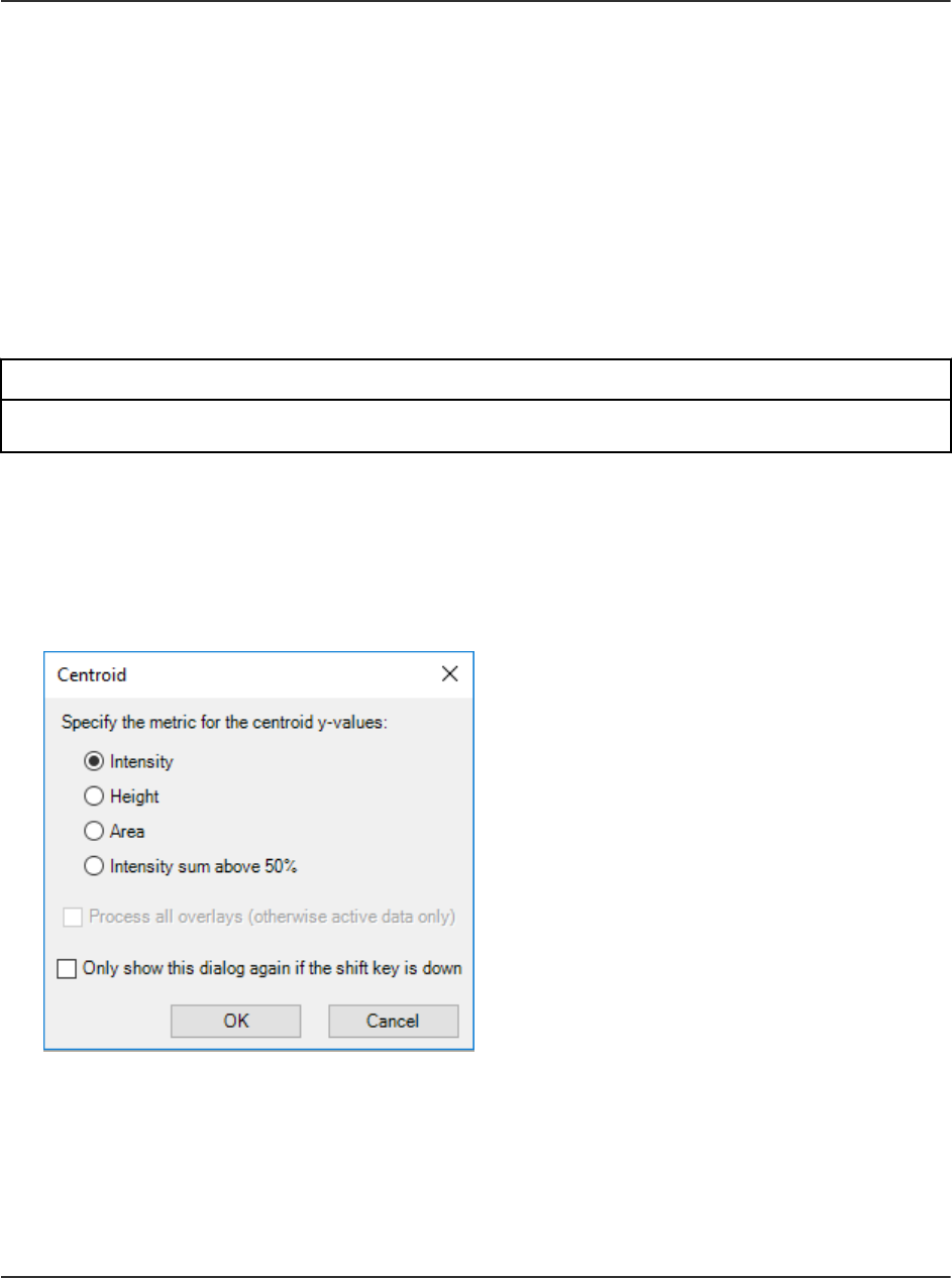
2. Type a value, in minutes, in the Total offset field.
3. If there are multiple traces in the active graph, then select Process all overlays (otherwise
active data only) to apply the operation to all of the traces.
If the Only show this dialog again if the shift key is down check box is selected, then the
selected action is always used unless the user holds the Shift key to change the option.
4. Select Use incremental offset (to fan out overlays) to spread the overlays apart in the
time direction.
5. Click OK.
Centroid a Spectrum
Prerequisite Procedures
• Open Samples.
Creates a centroid of a mass spectrum, that is, replaces a profile spectrum with mass and
intensity points for the detected peaks only.
1. Click Process > Centroid Spectrum.
Figure 6-19 Centroid Dialog
2. Select the metric to be used for the centroid process:
• Intensity: For each peak, the centroid Y-value is the intensity of the largest data point
comprising the peak.
• Height : This metric is similar to the Intensity metric except that the intensity is subtracted
by the baseline intensity when there is a baseline offset.
Operating Instructions—Processing
SCIEX OS Software for SCIEX Triple Quad and QTRAP
Systems
120/262
Software User Guide
RUO-IDV-05-9804-F

• Area: For each peak, the centroid Y-value is the total area of the peak. This is a true
integral because the reported value depends on both the intensity profile and the width of
the peak.
• Intensity sum above 50%: For each peak, the Y-value is the sum of the portion of the
intensities comprising the peak which are above 50% of the peak apex intensity. This
value is useful because it does not depend only on the intensity of a single data point,
as the Intensity and Height metrics do, and it is not influenced by the edges of the peak
which might be noisy or which might have interference.
3. If there are multiple traces in the active graph, then select Process all overlays (otherwise
active data only) to apply the operation to all of the traces.
If the Only show this dialog again if the shift key is down check box is selected, then the
selected action is always used unless the user holds the Shift key to change the option.
4. Click OK.
Export Data as Text
Prerequisite Procedures
• Open Samples.
Currently active spectrum or chromatogram is saved to a tab-delimited text file.
1. Click File > Export > Data as Text.
If spectral data is exported, then the Add Zero Intensity Points for Export dialog opens.
Figure 6-20 Add Zero Intensity Points for Export Dialog
2. If the Add Zero Intensity Points for Export dialog is open, then do one of the following:
• Click No, leave data as-is to exclude points with zero intensity from the exported file.
Operating Instructions—Processing
Software User Guide
RUO-IDV-05-9804-F
SCIEX OS Software for SCIEX Triple Quad and QTRAP
Systems
121/262

• Click Yes, add points with zero intensity to include points with zero intensity in the
exported file.
Then click OK.
3. Type a file name for the exported file.
4. Click Save.
Export the Peak List as Text
Prerequisite Procedures
• Open Samples.
The user can save the peak list for the currently active spectrum or chromatogram to a tab-
delimited text file. This file contains information such as the centroid X-value (mass or time),
peak area, height, and so on.
1. Click File > Export > Peak List as Text.
2. Type a file name for the exported file.
3. Click Save.
Print Data
Prerequisite Procedures
• Open Samples.
1. Click File > Print and then select the required option.
The Print dialog opens.
2. Select a printer, and then click Print.
Reset Options
Prerequisite Procedures
• Open the Explorer workspace.
The user can reset all of the options in the Explorer workspace to the default values. This
includes the options described in the previous section, as well as processing options. Resetting
the options only affects the currently logged-in Windows user, not other users of the same
computer.
Operating Instructions—Processing
SCIEX OS Software for SCIEX Triple Quad and QTRAP
Systems
122/262
Software User Guide
RUO-IDV-05-9804-F

1. Click Edit > Reset Options.
A confirmation dialog is shown.
2. Click OK.
Set Options
Prerequisite Procedures
• Open the Explorer workspace.
Use the features on each tab as required.
1. Click Edit > Options.
Figure 6-21 Options Dialog: Graph Appearance Tab
2. Set the options on each tab, as applicable. For descriptions of the options, refer to the
document: Help System.
3. Click OK.
Operating Instructions—Processing
Software User Guide
RUO-IDV-05-9804-F
SCIEX OS Software for SCIEX Triple Quad and QTRAP
Systems
123/262

Analytics Workspace
Access to features in this workspace is controlled by the role assigned to the user. Refer to the
document: Laboratory Director Guide.
Note: The controlled ways to output data from the Analytics workspace are: exporting Results
Tables, transferring data to a LIMS, and reporting. The other sources of output data, such as
copying and pasting from Results Tables, are not controlled. Do not use uncontrolled output
methods for regulated purposes.
The grouping of numbers is not supported in the Analytics workspace. Do not group numbers in
text boxes, for example, in the integration parameters, or grid such as a Results Table.
Processing methods include the criteria used to quantitate the peaks selected for integration.
Reviewers should review the data according to the criteria of peak integration and data
acceptance in the laboratory standard operating procedures (SOPs).
SCIEX OS can process data while it is being acquired by SCIEX OS or the Analyst software.
Any acquired samples can be added to the Results Table. To add samples that are being
acquired, wait until acquisition is complete and then add them to the Results Table.
Define the Default Processing Parameters for the Project
This option sets the default peak-finding parameters that are used when creating a processing
method. If there are more than a few components, then set the default values based on the
chromatography so that they do not need to be adjusted individually for every component.
However, no one set of parameters is likely to be ideal for all of the components, so it might be
necessary to adjust some of the parameters individually for some of the components.
1. In the Analytics workspace, click Projects > Project default settings.
Note: Make sure that the correct project name is selected in the status panel.
The Project Default Settings dialog opens.
2. On the Quantitative Processing page, perform these steps:
a. Select a signal-to-noise algorithm from the Signal to Noise Algorithm list.
b. Select an integration algorithm from the Integration Algorithm list and then set the
default parameters for quantitative processing.
For descriptions of the parameters, refer to the document: Help System.
3. On the Qualitative Processing page, select a library search algorithm from the Library
Search Algorithm list and then set the default parameters for qualitative processing.
For information about the algorithms, refer to the document: Help System.
Operating Instructions—Processing
SCIEX OS Software for SCIEX Triple Quad and QTRAP
Systems
124/262
Software User Guide
RUO-IDV-05-9804-F

4. On the Mass Reconstruction Processing page, select an integration algorithm from the
Integration Algorithm list and then set the default integration parameters for mass
reconstruction.
For descriptions of the parameters, refer to the document: Help System.
Note: Only the MQ4 and Summation algorithms are available.
5. Click Save.
6. Click Close.
Work with Workspace Layouts
Use the workspace layouts feature to save customized workspace layouts in the Analytics
workspace. The customized layout is saved with the Results file, and automatically applied when
the file is opened. This saves users time when they are analyzing results. A saved workspace
layout can be applied to other Results files. It can also be set as the default workspace layout for
a project, which is applied whenever a Results file in that project is opened. Workspace layouts
can be saved anywhere, including on local networks.
Users can change between different saved layouts to perform different types of data analysis on
their Results files.
Note: All workspace layouts are saved with the qlayout file name extension.
Note: No settings that change or alter data directly are preserved in a workspace layout.
The following table lists the UI elements that are saved with workspace layouts.
Table 6-3 UI Elements Saved with Workspace Layouts
Pane Saved UI Elements
Results Table • The Qualify for Rules Filters check box.
• Qualifying row filters.
• Table sort choice.
• Highlighted rows and columns.
• Table display settings.
• Column filters.
Note: When the workspace layout is applied to a different Results Table,
column filter settings are applied, if possible. If a filtered column does not
exist in a Results Table, or if a filtering option is not applicable, then the
setting is not applied.
Operating Instructions—Processing
Software User Guide
RUO-IDV-05-9804-F
SCIEX OS Software for SCIEX Triple Quad and QTRAP
Systems
125/262

Table 6-3 UI Elements Saved with Workspace Layouts (continued)
Pane Saved UI Elements
Views Menu • The Show hidden pane setting.
• Whether the Tabbed view option is selected.
Samples or
Components and
Groups
• Whether the Samples or Components and Groups list is open.
• Whether specific samples or components are selected to be shown in a
Results Table.
• In the Samples list, the setting for Options > Synchronize Sample
Selection.
• In the Components and Groups list, selection of All Internal Standards,
All Analytes, All Components, and Groups (where applicable)
options.
• In the Components and Groups list, the setting for Options > Show IS
Peak Review • Whether the Peak Review pane is open and if it is docked.
• The current View.
• Any selected Options, including the Peak review display settings
options and the XIC Graph Title option.
Calibration Curve
• Whether the Calibration Curve pane is open.
• The Show excluded standards, Show quality controls, Show
legend, Use percent Y-axis, and Log-log plot settings in the Options
menu.
Metric Plot
• Whether the Metric Plot pane is open.
• Link menu settings.
• Regression dialog settings.
• The Display "N/A" as 0.0, Show sample names, Show legend, Use
percent Y-axis, Start Y-axis at 0, and Connect with lines settings in
the Options menu.
Statistics Pane
• Whether the Statistics pane is open.
• Active Sample grouping selections.
• Active Metric selections.
Operating Instructions—Processing
SCIEX OS Software for SCIEX Triple Quad and QTRAP
Systems
126/262
Software User Guide
RUO-IDV-05-9804-F

Save the Current Workspace Layout
1. Open the Analytics workspace.
2. Open a Results Table.
3. Customize the workspace layout as required.
4. Click Views > Save current layout.
The Save Workspace Layout As dialog opens.
5. Type a name for the workspace layout and then click Save.
Apply Another Workspace Layout to the Current Project
Applying different workspace layouts to the current Results file allows the user to quickly perform
different types of results analyses on the same data.
1. Open the Analytics workspace.
2. Open a Results file.
3. Click Views > Apply different layout to current results.
The Apply a Workspace Layout dialog opens.
4. Click Browse, select a layout, and then click Open.
The Apply a Workspace Layout dialog shows a preview of the selected workspace layout.
5. Click OK.
Tip! Apply recently used workspace layouts by clicking Views > Recent layouts and
selecting a layout.
Set the Current Workspace Layout as Project Default
Setting a project default workspace layout preserves a layout between multiple sessions or
users. It also makes any new Results files created within the project open with the project default
workspace layout.
1. Open the Analytics workspace.
2. Open a Results file.
3. Customize the workspace layout to suit the project.
4. Click Views > Set current layout as project default.
The Default Workspace Layout for the Project dialog opens.
5. Type a name for the layout in the Default layout name field and then click OK.
6. Click Results > Save.
Operating Instructions—Processing
Software User Guide
RUO-IDV-05-9804-F
SCIEX OS Software for SCIEX Triple Quad and QTRAP
Systems
127/262

Set Project Secure Export Settings
Only a user who has been assigned to the Administrator role can perform this task.
If this option is selected, then data in the text file is encrypted during export. Set a password to
enable encryption.
1. In the Analytics workspace, click Projects > Project secure export settings.
Figure 6-22 Secure Export Settings Dialog
2. Select the Encrypt Results Table when exporting for this project check box.
3. Type a password in the Password field.
4. Type the password again in the Confirm Password field.
5. Click OK.
Enable the Project Modified Peak Warning
By default, this option is not selected. When it is selected, if a user changes a chromatogram in
a Results Table and then saves the changes, a warning message indicates that a change has
been made. The user can choose to continue saving or return to the Results Table.
In the Analytics workspace, click Projects > Enable project modified peak warning.
Create a Processing Method
Processing methods contain quantitative and qualitative settings for data processing. The Non-
targeted workflow is used for unknown components.
Tip! To edit an existing processing method, click Process Method > Open.
1. Open the Analytics workspace.
Operating Instructions—Processing
SCIEX OS Software for SCIEX Triple Quad and QTRAP
Systems
128/262
Software User Guide
RUO-IDV-05-9804-F

2. Click Process Method > New.
Tip! To edit the processing method for the current Results Table, click Process Method >
Edit embedded method and then continue with step 3.
3. On the Workflow page select at least one workflow and the reference samples. For
descriptions of the fields on this page, refer to the document: Help System.
Tip! To use the mass reconstruction workflow, select Quantitation only.
4. Select the Components page and then perform these steps:
a. If applicable, select the mass reconstruction workflow by clicking Options > Mass
Reconstruction and then clicking Yes in the confirmation dialog.
b. Complete the components table. For descriptions of the fields in this table, refer to the
document: Help System.
Note: The Mass Reconstruction workflow is only available when the integration algorithm is
set to MQ4 or Summation.
Tip! If a group is defined in the Components table, then the user can choose to sum
the ions in the group, even if the precursor ion and the experimental index are different
for the transitions. The summed ions are not shown in the table but are shown on the
Integration page and in the Results Table as group name > Sum. This feature is useful for
the quantitation of proteins and peptides.
Tip! If the retention time of the components is not known, then set the Retention Time
Mode for a mass or chemical formula to Find n peaks, where n is 1, 2, 5, 10, or all. The
software identifies the specified number of features with the greatest peak area, assigns the
appropriate retention time, and then performs a targeted peak processing workflow. When
processing is complete, the embedded method for the Results Table can be saved as a
targeted method.
Tip! To import components or components and integration parameters from a text file, use
the appropriate command on the Import menu. If the component information does not
contain concentration units, then the software uses the Concentration units defined on the
Project Default Settings dialog.
Note: Integration parameters cannot be imported from processing methods that use the
AutoPeak integration algorithm.
Note: Integration parameters can be imported from Analyst software quantitation methods.
Analyst software parameters are mapped to the corresponding SCIEX OS parameters, and
the project default settings are used for any parameters that cannot be mapped.
Operating Instructions—Processing
Software User Guide
RUO-IDV-05-9804-F
SCIEX OS Software for SCIEX Triple Quad and QTRAP
Systems
129/262

Note: Integration parameters can be imported from MultiQuant software quantitation
methods that do not use the SignalFinder algorithm. For MQ4 methods, the S/N Integration
Threshold is changed from 0, the default in the MultiQuant software, to the project default.
The parameters for the MultiQuant software are mapped to the corresponding parameters
for SCIEX OS.
5. Select the Integration page and then perform these steps:
a. Select the integration parameters for each component. For descriptions of the fields on
this page, refer to the document: Help System.
Tip! To define the rules for automatic outlier removal, click Options > Remove Outliers
Automatically. Refer to the document: Help System.
b. (Optional) To view the noise region, click Options > Show Noise Regions. Refer to the
section: Work With Noise Regions.
Note: Show Noise Regions is only shown when signal to noise algorithm is set to
Standard Deviation or Peak to Peak.
6. (If applicable) Select the Library Search page and then define the library search parameters.
For descriptions of the fields on this page, refer to the Help System.
7. Select the Calculated Columns page and then define any custom formulas to be used in
custom calculated columns. For descriptions of the fields on this page, refer to the Help
System.
Note: For more information about calculated columns, refer to the section: Calculated
Columns.
8. Select the Flagging Rules page and then select the rules to be used to flag results in
the Results Table. For descriptions of the fields on this page, refer to the document: Help
System.
Optionally, create custom flagging rules, or customize the following values for the predefined
rules:
• Acceptance criteria for the following:
• Accuracy of standards and quality controls
• Calculated concentration range for unknown samples
• Peak integration
• Traffic light settings for mass accuracy, retention time confidence, isotope match, library
score, and formula finder score
• Traffic light settings for ion ratio acceptance
Operating Instructions—Processing
SCIEX OS Software for SCIEX Triple Quad and QTRAP
Systems
130/262
Software User Guide
RUO-IDV-05-9804-F

Ion ratio is the peak response ratio, that is, the area or height of the qualifier and
quantifier.
Tip! To import flagging rules from a text file, click Import.
9. Select the Formula Finder page and then select the formula finder settings. For descriptions
of the fields on this page, refer to the document: Help System.
10. (If the Non-targeted workflow is selected) Select the Non-targeted Peaks page and then
define the Non-targeted search parameters. For descriptions of the fields on this page, refer
to the document: Help System.
11. Click Save.
Tip! If a Non-targeted method is created, then the current project default parameters are
used for peak integration, and those parameters are saved in the processing method file.
If the processing method contains the targeted analytes, then the customized integration
parameters for the targeted components will not affect the Non-targeted peak integration. If
the user changes the project default parameter later, then the changed parameter will not
impact the existing Non-targeted method, which still contains the parameters at the time
the method was created. Only the newly created non-targeted method uses the changed
parameters.
Process Data
1. Open the Analytics workspace.
2. Click Results > New.
3. On the Process New Results dialog, use the arrows ( and ) to select samples
to be processed.
4. Select a processing method in one of the following ways:
• Click Browse and then select a processing method and click Open.
• Click New and then create the new processing method. Refer to the section: Create a
Processing Method.
5. (Optional) Click Edit to edit the processing method. Refer to the section: Create a
Processing Method.
6. Select a comparison sample for non-targeted workflows.
7. Click Process.
Operating Instructions—Processing
Software User Guide
RUO-IDV-05-9804-F
SCIEX OS Software for SCIEX Triple Quad and QTRAP
Systems
131/262

Note: In Non-targeted analysis, automatic grouping by adduct is performed. The grouping
algorithm assigns adduct modifiers for compounds with the same retention time if the mass
difference between them is associated with a common adduct. This feature helps prevent
the investigation of duplicate compounds with different charge adducts.
If the data contains custom batch columns that have the same name as predefined
Results Table columns or existing formulas, then a warning message is shown. Click OK to
continue. An underscore (_) is added at the beginning of these column names.
8. To show or hide sample types, click the filter icon ( ) on the Sample Type column and then
select or clear the required check boxes.
9. To set the acceptance filters, click the filter icon ( ) on any of the acceptance columns,
select Filter by Flag, and then select Pass or Fail.
Note: The Acceptance columns include Accuracy, Accuracy Acceptance,
Asymmetry Factor, Calculated Concentration, Concentration Acceptance, Integration
Acceptance, Quality Retention Time Delta (min), Retention Time Error (%), and Total
Width.
10. To select qualitative confidence filters, click the Confidence traffic light and then select or
clear the required check boxes.
Note: After the Results Table is generated using the AutoPeak algorithm, if the user
changes the XIC width and the expected RT, then the data will be reprocessed using the
previous algorithm model unless the user updates the model using the new XIC width and
expected RT values.
11. To filter based on individual values for a Results Table column, click the filter icon ( )
on the column header and then select the check boxes for the values to be shown in the
Results Table.
Tip! To apply additional custom filters, select Text Filters.
Tip! To reapply the filter after a change to the Results Table, such as a change to the area
count, click Reapply Filter ( ).
12. Save the Results file in one of the following ways:
• Click Results > Save.
• To prevent changes to the Results Table, click Results > Lock results file and save.
Operating Instructions—Processing
SCIEX OS Software for SCIEX Triple Quad and QTRAP
Systems
132/262
Software User Guide
RUO-IDV-05-9804-F

Add Samples
Prerequisites
• In the Analytics workspace, a Results Table is open.
This option adds additional samples to a currently active Results Table.
1. Click More > Add samples.
2. In the Select Samples dialog, select the required samples.
• The Available pane shows the subfolders, wiff2 files, and samples available in the Data
folder for the current project.
• Expand individual folders to see any subfolders or wiff2 files. If the wiff2 file is expanded,
then it opens to show the available samples.
• Use the arrows to add (
) or remove ( ) samples.
• Select samples in the following ways:
• Double-click an individual sample.
• Select a sample or data file and then click .
• Drag a sample or data file from the left pane to the right pane.
Press Shift or Ctrl to select multiple files or samples before moving them.
3. Click OK.
A progress bar is shown while the new samples are integrated and added to the existing
table.
Customize the Results Table
Prerequisites
• In the Analytics workspace, a Results Table is open.
Select the numeric format and the columns to be shown in the Results Table. The column
settings can be applied to all of the Results Tables in the project.
Note: Some critical columns, such as Sample Name, Sample ID, Barcode, and so on, should
not be hidden when users customize the Results Table column settings.
Operating Instructions—Processing
Software User Guide
RUO-IDV-05-9804-F
SCIEX OS Software for SCIEX Triple Quad and QTRAP
Systems
133/262

Tip! If column names are truncated, then move the cursor over the field to show the column
name in a tooltip.
1. Click More > Table display settings.
The Results Table Display Settings dialog opens. For a description of the columns in the
Results Table, refer to the section: Results Table Columns.
Figure 6-23 Results Table Display Settings Dialog
Operating Instructions—Processing
SCIEX OS Software for SCIEX Triple Quad and QTRAP
Systems
134/262
Software User Guide
RUO-IDV-05-9804-F

Item Description
1 Click to select a column settings file previously saved using the Export
button. The dialog fields are updated to use the information from the
selected file.
2 Click to save the current dialog settings to a file. Use the Import button
to import and use these settings. This option lets the user switch
between different column layouts.
3 The name of the columns, shown in alphabetical order.
Note: This list also includes any calculated columns defined in the
processing method that was used to create the Results Table.
4 A checkmark indicates that the column is visible.
5 For numerical fields, use the format 0.00 for non-scientific notations and
use the format 0.00e0 for scientific notations. Change the decimal points
to indicate the precision of the numbers that are shown. Only a period
"." can be used as a decimal separator.
Note: Grouping of numbers is not supported.
6
The selected LIS Supported rows are predefined by the LIMS and the
column selections cannot be changed.
7 Click to use the column settings for future Results Tables.
8 Click to apply the changes and then close the dialog.
9 Click to abandon the changes and then close the dialog.
10 Select a category of Results Table columns. Users can filter the columns
shown in the Results Table based on the selection. Selecting a category
helps the user to easily find a column in the Results Table.
2. Select or clear the check box in the Visible column, as required.
Note: In addition to the columns described in the section: Results Table Columns, the
Results Table can contain custom calculated and text columns. Calculated columns are
identified with an asterisk.
3. (Optional) In the Number Format column, change the format to integer or scientific
notation.
4. (Optional) In the Number Format column, change the number of decimal points to be
shown.
5. Click OK.
Operating Instructions—Processing
Software User Guide
RUO-IDV-05-9804-F
SCIEX OS Software for SCIEX Triple Quad and QTRAP
Systems
135/262

The new settings are applied to the Results Table. The settings are also saved and applied
when a new Results Table is created or a previously saved Results Table is opened again.
Tip! Use the header row of the Results Table to adjust the column widths and column order.
Drag the header border to change the width. Drag the column header to another location in
the Results Table to change the column order. Click the filter icon ( ) on a column header
to apply a filter to the column. When the Export button is used to export a Results Table, the
column width, order, and filter settings are saved in the exported file.
Create a Report
Prerequisites
• In the Analytics workspace, a Results Table is open.
Tip! To select the analytes to be included in a report, use the Reportable column in the Results
Table. Refer to the section: Results Table Columns.
1. Click Reporting > Create Report and Save Results Table.
The Create Report dialog opens.
2. Select a template from the Template name list.
3. Select a report format.
4. To change the file name and location, click Browse, navigate to a different location, type a
File name, and then click Save.
Note: By default, reports are saved in
ProgramData\SCIEX\Analytics\Reporter\Reports.
5. Click the Create an individual report for each sample check box, if required.
6. (Optional) Select a different logo for the report:
a. Click Replace Logo.
b. Use the options in the Replace Logo dialog to modify the logo as required.
c. Click Save.
d. Click Cancel.
7. Click View Pages to view the report layout.
8. Click Create.
Operating Instructions—Processing
SCIEX OS Software for SCIEX Triple Quad and QTRAP
Systems
136/262
Software User Guide
RUO-IDV-05-9804-F

Tip! To report the selected results using a template such as Per Sample Quant, Per Sample
Qual, Per Sample Visible Rows Using Visible Analytes, or Positive Hits Qual, use filters or
hide the unwanted rows in the Results Table.
Tip! Click the example in the Template View in the Create Report dialog to view the
report template layout. To view a specific template, the user must have a jpg file with the
same name as the template in addition to the suffix [Snapshot_X], where X is the snapshot
number in the sequence. Do not use spaces between the file name and the suffix.
For example, All Peaks Qual.docx template would be named: All Peaks
Qual[Snapshot_1].jpg All Peaks Qual[Snapshot_2].JPG All Peaks Qual[Snapshot_3].jpg
Export and Save a Results Table
Prerequisites
• In the Analytics workspace, a Results Table is open.
Tip! To select the analytes to be exported, use the Reportable column in the Results Table.
Refer to the section: Results Table Columns.
1. Click Reporting > Export results > Export and save Results Table.
The Export dialog opens.
2. Select the options as required.
For descriptions of the options, refer to the document: Help System.
3. Click OK.
Export Results Table – Metric
Prerequisites
• In the Analytics workspace, a Results Table is open.
Note: The manufacturer assumes no responsibility or contingent liability, including indirect or
consequential damages, after data has been exported from the Analytics workspace.
Exporting Results Tables is one of the controlled methods for data output in the Analytics
workspace.
Operating Instructions—Processing
Software User Guide
RUO-IDV-05-9804-F
SCIEX OS Software for SCIEX Triple Quad and QTRAP
Systems
137/262

This feature is used to create a tab-delimited text file containing the information from the active
Results Table. Information is exported for all samples and either all components or just the
visible components for the one selected metric or field.
1. Click Reporting > Export results > Results Table - Metric.
The Export Metric dialog opens.
2. Select the column to export in the Metric field, and then set the options. Refer to the
document: Help System.
3. Click OK.
Transfer Results to a Watson LIMS
Prerequisites
• A Results Table is open and locked.
• The Watson LIMS software is open.
Note: A subset of the columns in the Results Table is transferred, including some hidden
columns, and some that are not designated as Reportable.
1. Click Reporting > Initiate Transfer to Watson LIMS.
The transfer dialog opens.
2. In the Watson LIMS software, import the data.
3. In the transfer dialog in SCIEX OS, do one of the following:
• If the transfer was successfully completed, then click Confirm.
• If the transfer was not successfully completed, then click Decline.
Transfer Results to Another LIMS
Prerequisite Procedures
• Configure the LIMS in the Configuration workspace. Refer to the section: Select Laboratory
Information Management System (LIMS) Settings.
• Open a locked Results Table.
Tip! To select the analytes to be exported, use the Reportable column in the Results Table.
Refer to the section: Results Table Columns.
1. Click Reporting > Transfer Results to LIMS.
Operating Instructions—Processing
SCIEX OS Software for SCIEX Triple Quad and QTRAP
Systems
138/262
Software User Guide
RUO-IDV-05-9804-F

The LIMS Transfer dialog opens.
2. Select a template from the Template list.
3. Click Transfer.
Work With Results Tables
Results Tables summarize the calculated concentration of an analyte, as well as the qualitative
analysis results such as library hits, formula finder results, and so on, in each unknown sample
based on the calibration curve. Results Tables also include the calibration curves, as well as
statistics for the results. The user can customize the Results Tables and view the Results Tables
in different layouts.
Note: Results Table columns with an asterisk (*) are custom text or calculated columns.
The data from a Results Tables can be exported to a txt file for use in other applications, such
as Microsoft Excel. The user can export all of the data in the Results Table or just the data in the
visible columns.
Tip! If multiple sessions of Results Tables have been tiled either vertically or horizontally, then
click Views > Reset layout to return the Results Tables to their original layout.
Use the right-click menu to edit the Results Table rows. To show this menu, click the right mouse
button anywhere in the Results Table.
Figure 6-24 Right-Click Menu
Table 6-4 Right-Click Menu Commands
Label Description
Copy Use this option to copy the current data to the clipboard.
Paste Use this option to paste data from the clipboard in the current
view.
Copy Entire Table Use this option to copy the entire table to the clipboard.
Fill Down (Components) Use this option to replicate the information in the
first selected row to all of the subsequent selected rows.
Operating Instructions—Processing
Software User Guide
RUO-IDV-05-9804-F
SCIEX OS Software for SCIEX Triple Quad and QTRAP
Systems
139/262

Table 6-4 Right-Click Menu Commands (continued)
Label Description
Select All Rows Use this option to select all of the rows in the currently active
Results Table. This is useful if the user subsequently wants to
apply a command, such as Copy, that operates on the selected
rows.
Apply Current Analyte's
Actual Concentrations to
All
(Analytes) If there is more than one analyte and all of the analytes
are present in these samples at the same concentration, then use
this option to provide a shortcut for setting the actual concentration
field for all of the analytes for the standard samples. To use this
feature:
1. Use the Components and Groups List to show only one
specific analyte in the table. Refer to the section: Components
and Groups List.
2. (Optional) Filter the Sample Type column to view only
standard samples.
3. Specify the actual concentration for the analyte, either by
typing in the cells or by selecting the column and pasting text
in it.
4. Select Apply Current Analyte's Actual Concentrations to
All.
Return to viewing all of the components and sample types, as
required.
Operating Instructions—Processing
SCIEX OS Software for SCIEX Triple Quad and QTRAP
Systems
140/262
Software User Guide
RUO-IDV-05-9804-F
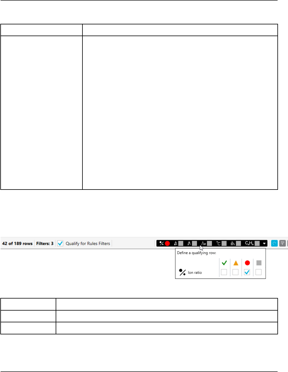
Table 6-4 Right-Click Menu Commands (continued)
Label Description
Apply Current IS's
Actual Concentrations to
All
(Internal standards) If there is more than one internal standard and
all of the internal standards are present in these samples at the
same concentration, then use this option to provide a shortcut
for setting the actual concentration field for all of the internal
standards for the standard samples. To use this feature:
1. Use the Components and Groups List to show only one
specific internal standard in the table. Refer to the section:
Components and Groups List.
2. (Optional) Filter the Sample Type column to view only
standard samples.
3. Specify the actual concentration for the internal standard,
either by typing in the cells or by selecting the column and
pasting text in it.
4. Select Apply Current IS's Actual Concentrations to All.
Return to viewing all of the components and sample types, as
required.
Results Table Filters
Use the fields at the top of the Results Table to view and filter content.
Figure 6-25 Filtering Controls
Table 6-5 Results Table Filters
Label Description
x of y rows Shows the number of visible rows (x) out of the total number of rows (y).
Filters Shows the number of columns to which filters are applied.
Operating Instructions—Processing
Software User Guide
RUO-IDV-05-9804-F
SCIEX OS Software for SCIEX Triple Quad and QTRAP
Systems
141/262

Table 6-5 Results Table Filters (continued)
Label Description
Qualify for
Rules Filters
Toggles the view of the Results Table between the rows that match the
acceptance criteria filters or confidence traffic filters and those that do
not. Acceptance criteria and confidence traffic lights are applied in the
processing method.
Reapply Filter
Reapplies the filter after a change to the Results Table, such as a change to
the area count.
Note: All filters are automatically reapplied when another filter is added or
changed.
Clear
Clears all filters.
Results Table Columns
Note:
• Columns with an asterisk (*) are custom text columns, calculated columns, or columns
created as a results of a combined flagging rule.
• Columns with names that begin with an underscore (_) are custom batch columns that have
the same name as a predefined Results Table column or formula.
• The Format column indicates how the field is validated in formulas.
• In columns that contain numbers, users can change the number format and the number of
significant digits. Choose between Decimal, Significant Digits, or Scientific Notation in
the Number Format column and then type the number of significant digits in the Number
Format Precision column in the Results Table Display Settings dialog.
Label Description Format LIS
Supported
Accuracy Shows the accuracy of standards and
quality control (QC) samples. For other
sample types, this value is set to N/A.
For standards of known concentration, the
accuracy of standards and QC samples
is defined as 100% × (Calculated
Concentration)/(Actual Concentration).
Number
Y
Operating Instructions—Processing
SCIEX OS Software for SCIEX Triple Quad and QTRAP
Systems
142/262
Software User Guide
RUO-IDV-05-9804-F

Label Description Format LIS
Supported
Accuracy
Acceptance
Shows the acceptance status of the
accuracy.
Text N
Acq. Method
Name
Shows the name of the acquisition method
used to acquire the sample.
Text Y
Acquisition Date
& Time
Shows the date and time at which the
sample was acquired.
Text Y
Actual
Concentration
For standards and QC samples, shows the
expected known concentration.
Number Y
Adduct/ Charge Shows the adduct or charge state of
the compound. In the targeted workflow,
this value is set by the user. In
the non-targeted workflow, this value
is automatically set by the software if
grouping by adduct is enabled.
Text
N
Area Shows the detected peak area. If no peak
was detected, then this value is set to N/A.
Number Y
Area / Height Shows the detected peak area divided by
the height. If a peak was not detected,
then this value is set to N/A.
Number N
Area Ratio For analytes that use an internal standard,
shows the ratio of the analyte Area to
the IS Area. For internal standards, or for
analytes without an internal standard, this
value is set to N/A.
Number
Y
Operating Instructions—Processing
Software User Guide
RUO-IDV-05-9804-F
SCIEX OS Software for SCIEX Triple Quad and QTRAP
Systems
143/262

Label Description Format LIS
Supported
Area Ratio of
comparison
Shows the area ratio of the sample/control
sample.
• If no peak is found in the control, then
the value is N/A.
• If no peak is found in the sample, then
the value is 0.
• If every peak in the sample is below the
Area Ratio Threshold, then the value
is N/A.
• If a comparison sample is not used,
then the value is No control sample.
• For the control sample, the area ratio
for found peaks is always 1.
Applicable to qualitative workflows only.
Number N
Asymmetry
Factor
Shows the distance from the center line
of the peak to the back slope, divided
by the distance from the center line of
the peak to the front slope, with all of
the measurements made at 10% of the
maximum peak height.
Number
Y
AutoPeak
Asymmetry
Shows the ratio of the asymmetry of the
integrated peak to the symmetry expected
based on the model. A ratio of 1 indicates
a good fit. If the value is not 1, then
the ion source might be saturated, or the
integration might not be correct.
Applicable only to processing methods
that use the AutoPeak integration
algorithm.
Number
N
Operating Instructions—Processing
SCIEX OS Software for SCIEX Triple Quad and QTRAP
Systems
144/262
Software User Guide
RUO-IDV-05-9804-F

Label Description Format LIS
Supported
AutoPeak
Candidate Model
Quality
Shows the suitability of the peak for use
in the creation of a peak model. If the
value is significantly greater than 1, then
the sample used to create the quantitation
method is unsuitable. Use a peak with a
larger response to create the model, and
then apply that peak to all samples.
Applicable only to processing methods
that use the AutoPeak integration
algorithm.
Number
N
AutoPeak Group
Confidence
Shows the probability that the group
of real peaks is integrated and that
the integration does not include a false
positive noise peak.
Applicable only to processing methods
that use the AutoPeak integration
algorithm.
Number
N
AutoPeak
Integration
Quality
Shows the quality of the data. The quality
is represented as a value from 0 to
1. If the quality is less than 0.6, then
investigate the integration further.
Applicable only to processing methods
that use the AutoPeak integration
algorithm.
Number
N
AutoPeak Model
Source
Shows the names of the samples and
components that were used for peak
modeling. If the component used for
modeling is not the same as the
component that was integrated, then
review the model to determine whether it
is appropriate.
Applicable only to processing methods
that use the AutoPeak integration
algorithm.
Number
N
Operating Instructions—Processing
Software User Guide
RUO-IDV-05-9804-F
SCIEX OS Software for SCIEX Triple Quad and QTRAP
Systems
145/262

Label Description Format LIS
Supported
AutoPeak Num
Peaks
Shows the number of adjacent convoluted
peaks that were detected by the algorithm.
Applicable only to processing methods
that use the AutoPeak integration
algorithm.
Number
N
AutoPeak
Peak Width
Confidence
Shows the level of confidence in the peak
width. A value of 1 indicates that the actual
peak width and the expected peak width
are equal. A value greater than 1 indicates
that the actual peak width is greater than
the expected peak width. A value less than
1 indicates that the actual peak width is
less than the expected peak width, or that
the peak is broader because of a change
in chromatographic conditions.
Applicable only to processing methods
that use the AutoPeak integration
algorithm.
Number N
AutoPeak
Saturated acc
If the Saturation correction option
was used and the corresponding peak
was saturated, so that the fitted model
extends above the peak, then this field
shows Yes. Otherwise, the column is
blank. If the accuracy and %CVs for
samples at higher concentrations are not
within acceptable ranges, then adjust the
Saturation correction.
Applicable only to processing methods
that use the AutoPeak integration
algorithm.
Text N
Operating Instructions—Processing
SCIEX OS Software for SCIEX Triple Quad and QTRAP
Systems
146/262
Software User Guide
RUO-IDV-05-9804-F

Label Description Format LIS
Supported
Barcode Shows the unique ID for a sample. The
unique ID is initialized from the value
originally specified in the batch used to
acquire the data.
The Barcode can contain up to 20
characters. The Barcode cannot contain
any of these invalid characters: \ / : * ? " <
> |= or characters 0 to 31 from the ASCII
table.
Text
Y
Baseline Delta/
Height
Shows the absolute value of the difference
between the height of the baseline, at the
start of the peak and the end of the peak,
and the actual peak height. Values greater
than 0.1 indicate that the baseline might
not have been integrated correctly and
that the peak should be reviewed.
Number
N
Calculated
Concentration
For standards of known concentration,
shows the value of the back-calculated
concentration from the calibration curve.
Regression equations describe how the
regression is performed for the various
regression types and weighting.
Number
Y
Combined Score (Optional) Shows a single number score
that can be used for relative comparison
purposes.
Applicable to qualitative workflows only.
Number
N
Comparison Shows the components in the comparison
sample.
Number N
Component
Comment
Shows an arbitrary comment for the
analyte or internal standard that applies to
all of the samples.
Text N
Component
Group Name
Shows any group name associated with
the analyte or internal standard.
Text N
Component
Index
Shows the index of the analyte or
internal standard in the original processing
method.
Number Y
Operating Instructions—Processing
Software User Guide
RUO-IDV-05-9804-F
SCIEX OS Software for SCIEX Triple Quad and QTRAP
Systems
147/262

Label Description Format LIS
Supported
Component
Name
Shows the name of the analyte or internal
standard.
This column is always visible in the
Results Table. In the Column Settings
dialog, the check box is not available.
The Component Name can contain up to
50 characters.
Note:
• The Component Name can only be
changed in the processing method and
not in the Results Table.
• This column is mandatory for a
Laboratory Information Management
System (LIMS) transfer.
Text Y
Component Type Shows the analyte type: Quantifier,
Qualifier, or Internal Standard.
Text N
Conc. Units Shows the concentration units. Text Y
Concentration
Acceptance
Shows the acceptance status of the
calculated concentration.
Number N
Concentration
Ratio
For analytes that use an internal
standard, shows the ratio of the
Actual Concentration to the IS Actual
Concentration. For internal standards, or
for analytes without an internal standard,
this value is set to N/A.
Number
N
Difference from
Average Sample
Time
Shows the difference between the analysis
time for this sample and the average
analysis time for all samples.
Number N
Dilution Factor Shows the factor by which the sample has
been diluted. This factor is used in the
calculation of the calibration curve.
Number Y
End Time Shows the ending retention time of the
detected peak, in minutes.
Number Y
Operating Instructions—Processing
SCIEX OS Software for SCIEX Triple Quad and QTRAP
Systems
148/262
Software User Guide
RUO-IDV-05-9804-F

Label Description Format LIS
Supported
End Time at 10% Shows the time, in minutes, along the
back side of the peak where the intensity
is at 10% of the peak height.
Number N
End Time at 5% Shows the time, in minutes, along the
back side of the peak where the intensity
is at 5% of the peak height.
Number N
Expected Ion
Ratio
Shows the expected ion ratio for unknown,
QC, and standard samples.
For each component in a group, the
Expected Ion Ratio is the average of
the ion ratios of its standards. A standard
is not included in the calculation of the
Expected Ion Ratio of the component if
these conditions apply:
1. The peak area is N/A.
2. The Use column is not selected.
Number Y
Expected RT Shows the original expected retention time
from the processing method, in minutes.
Number Y
Expected MW Shows the original expected molecular
weight, from the processing method, in
Da.
Applicable to mass reconstruction
workflows only.
Number
Y
Formula (Optional) Shows a valid chemical formula.
If the chemical formula is invalid, then
it is not retained by the software. If
the chemical formula is valid, then the
Mass (Da) and Isotope columns are auto-
populated.
Text
Y
Operating Instructions—Processing
Software User Guide
RUO-IDV-05-9804-F
SCIEX OS Software for SCIEX Triple Quad and QTRAP
Systems
149/262

Label Description Format LIS
Supported
Formula
Confidence
Shows, the level of confidence in the
Formula Finder Score, as a percentage.
It is calculated based on:
• How well the current MS spectrum
fits the theoretical spectrum for the
compound, based on mass.
• How well the acquired MS/MS
spectrum fits the MS/MS spectrum
found in the LibraryView software
database.
The MS spectrum score has twice the
weight of the MS/MS spectrum score.
Applicable to qualitative workflows only.
Text N
Formula Finder Shows the single number score that can
be used for relative comparison purposes.
The value is can be updated using data
from the Peak Review Formula Finder
Results Table.
Applicable to qualitative workflows only.
Number
N
Formula Finder
Results
(Optional) Shows the best match of the
formula finder results.
Applicable to qualitative workflows only.
Text
N
Formula Finder
Score
(Optional) Shows a single number score
that can be used for relative comparison
purposes.
Number Y
Found at
Fragment
(Optional) Shows the best requested
Fragment Mass (Da) at which matching
spectra were found.
Applicable to qualitative workflows only.
Number
Y
Operating Instructions—Processing
SCIEX OS Software for SCIEX Triple Quad and QTRAP
Systems
150/262
Software User Guide
RUO-IDV-05-9804-F

Label Description Format LIS
Supported
Found at Mass (Optional) Shows the best requested
Extraction Mass (Da) at which the
matching spectra were found.
Applicable to qualitative workflows only.
Number
Y
Fragment Mass (Optional) Shows the fragment mass, as
specified in the method. The precursor
of the fragment is extracted from the
MS/MS in the Extraction Mass (Da)
column. When provided, this value must
be numeric.
Number
Y
Fragment Mass
Error (ppm)
(Optional) Shows the difference between
the Found at Fragment and the Fragment
Mass, in ppm.
Number Y
Fragment Mass
Error (mDa)
(Optional) Shows the difference between
the Found at Fragment and the Fragment
Mass, in mDa.
Number Y
Fragment Mass
Error Confidence
(Optional) Shows the level of confidence in
the fragment mass error.
Text Y
Height Shows the detected peak height. If a peak
was not detected, then this value is set to
N/A.
Number Y
Height Ratio For analytes that use an internal standard,
shows the ratio of the Height to the
IS Height. For internal standards, or for
analytes without an internal standard, this
value is set to N/A.
Number
Y
Index Shows the index of the row in the original,
unsorted order. If the table is sorted based
on another column, then it can be returned
to the original order by sorting on this
column.
Number
N
Injection Volume Shows the volume of the sample stored
in the method and injected by the
autosampler.
Number Y
Operating Instructions—Processing
Software User Guide
RUO-IDV-05-9804-F
SCIEX OS Software for SCIEX Triple Quad and QTRAP
Systems
151/262

Label Description Format LIS
Supported
Integration
Acceptance
Shows how closely the peak integration
meets the acceptance criteria. It is
calculated based on these factors, as
configured in the flagging rules:
• Integration quality
• Assymetry factor
• Total peak width, in minutes
• Retention time error, measured as a
percentage or in minutes
Number N
Integration Type Shows the type of integration.
• Baseline: A standalone peak that was
integrated in the usual way.
• Valley: Indicates that there were two
adjacent peaks and that the signal
did not return to the baseline value
between them.
• N/A: Indicates that a peak was not
detected.
• Manual: Indicates that the peak was
manually integrated.
Text Y
Operating Instructions—Processing
SCIEX OS Software for SCIEX Triple Quad and QTRAP
Systems
152/262
Software User Guide
RUO-IDV-05-9804-F

Label Description Format LIS
Supported
Ion Ratio Shows the ion ratio. Ion ratios are
determined when at least two MRM
transitions from a single analyte have
been collected in a group.
All of the analytes in a group constitute
an analyte subgroup. All of the internal
standards in a group constitute an IS
subgroup. The first component in a
subgroup is used as a quantifier ion.
The remainder of the components in the
subgroup are used as qualifier ions.
Ion Ratio = (Peak Area or Height
of Qualifier)/(Peak Area or Height of
Quantifier)
The ion ratio can be calculated for either
the peak area or the peak height. If the
processing method uses the area for the
regression of the first component, that is,
the component for which the component
index is 1, in the Results Table, then the
peak area is used to calculate the ion
ratio for the entire Results Table. If the
height is used for the regression of the first
component, then the peak height is used
for the calculation.
• If a component is not a member of a
group, then the Ion Ratio value is set
to N/A.
• If a peak is not found, then the Ion
Ratio value is set to N/A.
• If the ion ratio is applied to all of the
components in both of the analyte and
IS subgroups, then the qualifier is the
quantifier.
• If the integration changes for either of
the quantifier or the qualifier peaks,
then the ion ratio is calculated again.
Number
Y
Operating Instructions—Processing
Software User Guide
RUO-IDV-05-9804-F
SCIEX OS Software for SCIEX Triple Quad and QTRAP
Systems
153/262

Label Description Format LIS
Supported
Note: The user can define flagging rules
for the ion ratio in the processing method.
Ion Ratio
Acceptance
Shows the acceptance status of the ion
ratio.
Number N
Ion Ratio
Confidence
Shows the level of confidence in the ion
ratio.
Applicable to qualitative workflows only.
Text
N
IS Shows whether the row is an internal
standard. A selected check box indicates
that the component for the row is an
internal standard, not an analyte.
Note: The IS check box is
automatically selected for sample names
containing .heavy or -cis because these
samples are defined as internal standards
in proteomics workflows. For other
workflows, they are not internal standards,
so the IS check box should be cleared.
Number N
IS Actual
Concentration
Shows the actual concentration of the
internal standard associated with the
current analyte. For internal standards, or
for analytes without an internal standard,
this value is set to N/A.
Number
N
IS Area Shows the area for the internal standard
associated with the current analyte. For
internal standards, or for analytes without
an internal standard, this value is set to
N/A.
Number
N
IS Area / Height Shows the ratio of the IS Area to
the IS Height for the internal standard
associated with the current analyte. For
internal standards, or for analytes without
an internal standard, this value is set to
N/A.
Number
N
Operating Instructions—Processing
SCIEX OS Software for SCIEX Triple Quad and QTRAP
Systems
154/262
Software User Guide
RUO-IDV-05-9804-F

Label Description Format LIS
Supported
IS Baseline
Delta / Height
Shows the absolute value of the height
difference between the baseline, at the
start of the peak and the end of the peak,
and the actual peak height for the internal
standard. Values greater than 0.1 indicate
that the baseline might not have been
integrated correctly and that the peak
should be reviewed.
Number
N
IS Comment Shows an arbitrary comment for the
internal standard associated with the
current analyte. For internal standards, or
for analytes without an internal standard,
this value is set to N/A.
Text
N
IS End Time Shows the time that the acquisition
ends for the internal standard associated
with the current analyte. For internal
standards, or for analytes without an
internal standard, this value is set to N/A.
Number
N
IS Expected MW Shows the expected molecular weight
for the internal standard associated with
the current analyte, in Da. For internal
standards, or for analytes without an
internal standard, this value is set to N/A.
Applicable to mass reconstruction
workflows only.
Number
Y
IS Expected RT Shows the expected retention time for
the internal standard associated with the
current analyte. For internal standards, or
for analytes without an internal standard,
this value is set to N/A.
Number
N
IS Height Shows the height for the internal standard
associated with the current analyte. For
internal standards, or for analytes without
an internal standard, this value is set to
N/A.
Number
N
Operating Instructions—Processing
Software User Guide
RUO-IDV-05-9804-F
SCIEX OS Software for SCIEX Triple Quad and QTRAP
Systems
155/262

Label Description Format LIS
Supported
IS Integration
Type
Shows the type of integration for the
internal standard associated with the
current analyte. For internal standards, or
for analytes without an internal standard,
this value is set to N/A.
Text
N
IS Mass Info Shows the mass information for the
internal standard associated with the
current analyte. For internal standards, or
for analytes without an internal standard,
this value is set to N/A.
Text
N
IS MW Shows the found molecular weight for
the internal standard associated with
the current analyte, in Da. For internal
standards, or for analytes without an
internal standard, this value is set to N/A.
Applicable to mass reconstruction
workflows only.
Number
N
IS MW Delta (Da) Shows the difference between the
expected and found molecular weight for
the internal standard, in Da.
Applicable to mass reconstruction
workflows only.
Number
Y
IS MW Delta
(ppm)
Shows the difference between the
expected and found molecular weight for
the internal standard, in ppm.
Applicable to mass reconstruction
workflows only.
Number
Y
IS Name Shows the name of the internal standard
associated with the current analyte. For
internal standards, or for analytes without
an internal standard, this value is set to
N/A.
Text
N
Operating Instructions—Processing
SCIEX OS Software for SCIEX Triple Quad and QTRAP
Systems
156/262
Software User Guide
RUO-IDV-05-9804-F

Label Description Format LIS
Supported
IS Peak
Comment
Shows the peak comment for the internal
standard associated with the current
analyte. For internal standards, or for
analytes without an internal standard, this
value is set to N/A.
Text
N
IS Quality Shows the quality of the internal standard
associated with the current analyte. For
internal standards, or for analytes without
an internal standard, this value is set to
N/A.
Number
N
IS Region Height Shows the height for the internal standard
region. For internal standards, or for
analytes without an internal standard, this
value is set to N/A.
Number
N
IS Retention
Time
Shows the retention time for the internal
standard associated with the current
analyte. For internal standards, or for
analytes without an internal standard, this
value is set to N/A.
Number
N
IS Signal / Noise Shows the signal-to-noise ratio for the
internal standard associated with the
current analyte. For internal standards, or
for analytes without an internal standard,
this value is set to N/A.
Number
N
IS Start Time Shows the start time for the internal
standard associated with the current
analyte. For internal standards, or for
analytes without an internal standard, this
value is set to N/A.
Number
N
IS Total Width Shows the total width for the internal
standard associated with the current
analyte. For internal standards, or for
analytes without an internal standard, this
value is set to N/A.
Number
N
Operating Instructions—Processing
Software User Guide
RUO-IDV-05-9804-F
SCIEX OS Software for SCIEX Triple Quad and QTRAP
Systems
157/262

Label Description Format LIS
Supported
IS Width at 50% Shows the width at 50% for the internal
standard associated with the current
analyte. For internal standards, or for
analytes without an internal standard, this
value is set to N/A.
Number
N
Isotope
Confidence
Shows the level of confidence in the
isotope ratio.
Applicable to qualitative workflows only.
Text
N
Isotope Ratio
Difference
Identifies the difference between the
theoretical isotope pattern, based on the
formula, and isotope pattern from the
acquired spectra.
Applicable to qualitative workflows only.
Number
N
LC Method Shows the name of the LC method used to
acquire the data.
Text N
Library
Confidence
Shows the level of confidence in the
Library Hit based on the Library Score
of the hit.
Applicable to qualitative workflows only.
Text
N
Library Hit Shows the compound name of the best
library match, that is, the compound with
the highest purity score and the formula
matching the requested formula.
The value is can be updated using data
from the Peak Review Library Search
Results grid. Applicable to qualitative
workflows only.
Text
N
Library Score Shows how well the library match fits the
found mass.
Applicable to qualitative workflows only.
Number
N
Operating Instructions—Processing
SCIEX OS Software for SCIEX Triple Quad and QTRAP
Systems
158/262
Software User Guide
RUO-IDV-05-9804-F

Label Description Format LIS
Supported
Mass Error
(ppm)
Shows the difference between the found
mass and the extraction mass, expressed
in parts per million.
Applicable to qualitative workflows only.
Number
N
Mass Error
(mDa)
Show the difference between the found
mass and the extraction mass, expressed
in milliDaltons.
Applicable to qualitative workflows only.
Number
N
Mass Error
Confidence
Shows the level of confidence in mass
error.
Applicable to qualitative workflows only.
Text
N
Mass Info Shows the mass information associated
with the component.
• For MRM experiments, this is Q1/Q3
and for profile, or full scan, experiments
it is Start - Stop.
• For UV, ADC, or DAD experiments, it
is the wavelength (DAD) or channel
information (UV/ADC).
If the fragment mass exists it will be used
for XIC extraction.
If there is no fragment mass, then the
precursor mass should be used for XIC
extraction.
Text Y
Modified Shows whether the peak-finding
parameters have been modified. A
selected check box indicates that the
peak-finding parameters in the processing
method have been modified, using the
Peak Review pane.
Number
Y
MS Method Shows the name of the MS method used
to acquire the data.
Text N
Operating Instructions—Processing
Software User Guide
RUO-IDV-05-9804-F
SCIEX OS Software for SCIEX Triple Quad and QTRAP
Systems
159/262

Label Description Format LIS
Supported
MW Shows the found molecular weight of the
analyte, from the reconstructed graph, in
Da.
Applicable to mass reconstruction
workflows only.
Number
Y
MW Delta (Da) Shows the difference between the
expected and found molecular weight, in
Da.
Applicable to mass reconstruction
workflows only.
Number
Y
MW Delta (ppm) Shows the difference between the
expected and found molecular weight, in
ppm.
Applicable to mass reconstruction
workflows only.
Number
Y
Non-Targeted
Peak
Indicates whether the peak was found by
the Enhanced Peak Finder.
Applicable to qualitative workflows only.
Number
N
Operator Name Shows the name of the instrument
operator who acquired the sample.
Text Y
Original
Filename
Shows the name of the file. Text Y
Operating Instructions—Processing
SCIEX OS Software for SCIEX Triple Quad and QTRAP
Systems
160/262
Software User Guide
RUO-IDV-05-9804-F

Label Description Format LIS
Supported
Outlier Reasons When the automatic removal of outliers
has been enabled in the quantitation
method, shows which criterion was found
to be outside of the predetermined limits
for the component.
The Outlier Reasons column is linked to
the rules for automatic removal of outliers
in the quantitation method. It is a preset
column in the Results Table.
The reason the outlier is flagged:
• Accuracy
• Concentration
• Ion ratio
If there is a peak for only one of
the quantifier or qualifier, then the ion
ratio is flagged for both components.
If neither of these components have
peaks, then the ion ratio is not flagged
for either of the components.
• Cannot calculate the expected ion ratio
• A custom flagging rule created by the
user has failed
Text N
Peak Comment Shows an arbitrary comment for the row. Text N
Plate Number Shows the plate number of the
autosampler used to acquire the data, as
indicated in the Batch Editor.
Text Y
Points Across
Baseline
Shows the number of scans across the
peak.
Number N
Points Across
Half Height
Shows the number of scans across the
peak, at approximately 50% of the height.
Number N
Polarity Shows the polarity of the experiment used
to acquire the sample.
Text N
Operating Instructions—Processing
Software User Guide
RUO-IDV-05-9804-F
SCIEX OS Software for SCIEX Triple Quad and QTRAP
Systems
161/262

Label Description Format LIS
Supported
Precursor Mass Shows the processing input parameters
taken from the processing method.
This column is always visible in the
Results Table. In the Column Settings
dialog, the check box is not available.
Number
N
Proc. Method
Name
Shows the name of the processing method
that created the Results Table.
Text Y
Quality Shows the quality of the integrated peak.
The area of the integrated peak and the
area of a larger RT window are compared.
A value of 0 indicates that the peak is
poorly integrated, or that a peak is not
present. A value of 1.0 indicates a well-
integrated peak that need not be reviewed.
Number
N
Rack Number Shows the rack number of the
autosampler used to acquire data, as
specified in the Batch Editor.
Text Y
Region Height Shows the peak height of the largest peak
in the vicinity of the detected peak. This is
useful in conjunction with the Quality field.
Peaks with a low quality that also have
a reasonable Region Height must be
reviewed. If the Region Height is small,
then a significant peak is not present.
Number
N
Relative RT For analytes that are using an internal
standard, shows the ratio of the Retention
Time to the IS Retention Time. For
internal standards, or for analytes without
an internal standard, this value is set to
N/A.
Number
Y
Reportable Shows whether the result is included in
reports, exports, and LIMS transfers.
Number Y
Retention Time Shows the actual retention time of the
detected peak, in minutes.
Number Y
Retention Time
Delta (min)
Shows the difference between the
retention time defined for the mass and
the actual retention time.
Number N
Operating Instructions—Processing
SCIEX OS Software for SCIEX Triple Quad and QTRAP
Systems
162/262
Software User Guide
RUO-IDV-05-9804-F

Label Description Format LIS
Supported
Retention Time
Error (%)
Shows the percent error found between
"Found at RT" and "Expected RT".
Applicable to qualitative workflows only.
Number
N
RT Confidence Shows the confidence in the retention
time.
Applicable to qualitative workflows only.
Text
N
Sample
Comment
Shows a user-specified comment for the
sample.
Text Y
Sample ID Shows a user-specified identifier for the
sample. The Sample ID is specified in the
Batch Editor prior to sample submission
for acquisition.
If the standard addition workflow is
enabled in the processing method, then
the Sample ID is used as a group
identifier for each standard addition
group. SCIEX OS links each sample
with an unknown analyte concentration
to samples to which known and varying
concentrations of the same analyte have
been added.
The Sample ID can contain up to 252
characters. The Sample ID cannot contain
any of these invalid characters: \ / : * ? " <
> |= or characters 0 to 31 from the ASCII
table.
Text Y
Sample Index Shows the index of the current sample.
Note: This column is locked and always
displayed at the left side of the Results
Table.
Number
Y
Operating Instructions—Processing
Software User Guide
RUO-IDV-05-9804-F
SCIEX OS Software for SCIEX Triple Quad and QTRAP
Systems
163/262

Label Description Format LIS
Supported
Sample Name Shows a user-specified name for the
sample. The Sample Name is specified
in the Batch Editor prior to sample
submission for acquisition.
The Sample Name must contain from 1
to 252 characters. The Sample Name
cannot contain any of these invalid
characters: \ / : * ? " < > |= or characters
0 to 31 from the ASCII table.
Note: This column is locked and always
displayed at the left side of the Results
Table.
Text Y
Sample Type Shows the type of sample. Text Y
Scanned
Barcode
Shows the barcode scanned prior to the
injection.
Text Y
Signal / Noise Shows an estimate of the ratio of the peak
height for the detected peak to the noise
present in the chromatogram.
For the AutoPeak integration algorithm,
noise is estimated using the calculated
relative noise and the baseline at the
peak apex position. The MQ4 algorithm
uses a similar approach, except that the
baseline is estimated using the entire
chromatogram.
Number
Y
Slope of
Baseline
Shows the slope of the integrated peak
from the baseline:
((intensity at peak stop) – (intensity at
peak start)) ÷ peak width
Number
N
Start Time Shows the starting retention time of the
detected peak, in minutes.
Number Y
Start Time at
10%
Shows the time, in minutes, along the front
side of the peak where the intensity is at
10% of the peak height.
Number N
Operating Instructions—Processing
SCIEX OS Software for SCIEX Triple Quad and QTRAP
Systems
164/262
Software User Guide
RUO-IDV-05-9804-F

Label Description Format LIS
Supported
Start Time at 5% Shows the time, in minutes, along the front
side of the peak where the intensity is at
5% of the peak height.
Number N
Std Addition
Accuracy
Shows the accuracy of samples of
known concentrations that are quantified
by the addition of standards of varying
concentration. When the standard addition
workflow is enabled in the processing
method, the Sample Type for all samples
is automatically set to Standard. If the
Sample Type is changed to another type,
or if the standard addition workflow is not
enabled, then this value is set to N/A. For
samples of known concentration, such as
a quality control sample in a batch, the Std
Addition Accuracy is defined as:
100% x (Std Addition Calculated
Concentration)/(Std Addition Actual
Concentration).
Number N
Std Addition
Actual
Concentration
Shows the user-specified expected known
concentration for samples that are
quantified by standard addition. For
example, a quality control sample in
a batch. If the Sample Type is not
Standard, then this value is set to N/A.
Number
N
Operating Instructions—Processing
Software User Guide
RUO-IDV-05-9804-F
SCIEX OS Software for SCIEX Triple Quad and QTRAP
Systems
165/262

Label Description Format LIS
Supported
Std Addition
Calculated
Concentration
Shows the value of the back-calculated
concentration by extrapolating the
standard addition curve to the X-intercept
using linear regression and no weighting.
For samples that are quantified by
standard addition, the Std Addition
Calculated Concentration is defined as:
Intercept/Slope
If the Sample Type is not Standard, if the
standard addition workflow is not enabled
in the processing method, or if a peak is
not found in the unspiked samples of a
standard addition group, then this value is
set to N/A.
Number N
Super group ID Scout Triggered MRM (stMRM) algorithm,
group mode: The name of the super
group to which a marker transition and
dependent transition have been assigned.
Text
N
Tailing Factor Shows the distance from the front slope
of the peak to the back slope, divided
by twice the distance from the center line
of the peak to the front slope. All of the
measurements are made at 5% of the
maximum peak height.
Number
N
Time Since First
Sample (min)
Shows the amount of time, in minutes,
since the acquisition of the first sample
started.
Number N
Time Since Last
Sample (sec)
Shows the amount of time, in seconds,
since the acquisition of the last sample
started.
Number N
Total Width Shows the chromatographic peak width, in
minutes, at the baseline.
Number Y
Operating Instructions—Processing
SCIEX OS Software for SCIEX Triple Quad and QTRAP
Systems
166/262
Software User Guide
RUO-IDV-05-9804-F

Label Description Format LIS
Supported
Used Shows whether the result is used.
• For all samples, a selected check box
indicates that the result is used in
the calculation of reference values and
execution of flagging rules.
• For standard samples, a selected
check box indicates that the result
is used in the construction of the
calibration curve, regression, and
statistics calculations.
• For QC samples, a selected check box
indicates that the result is used for
the calculation of the quality control
statistics.
• For other sample types, a selected
check box indicates that the result is
used in calculations.
Number Y
Vial Number Shows the vial number in the autosampler
used to acquire data, as originally
specified in the batch.
Text Y
Width at 10% Shows the width of the peak, measured at
10% of the peak height.
Number N
Width at 5% Shows the width of the peak, measured at
5% of the peak height.
Number N
Width at 50% Shows the chromatographic peak width, in
minutes, of the detected peak measured at
half of the apex intensity.
Number Y
XIC Width (Da) Shows the width of the extracted ion
chromatogram, in Daltons.
Number Y
XIC Width (ppm) Shows the width of the extracted ion
chromatogram, in ppm (parts per million).
Number Y
Operating Instructions—Processing
Software User Guide
RUO-IDV-05-9804-F
SCIEX OS Software for SCIEX Triple Quad and QTRAP
Systems
167/262

Acceptance Filters
Use the Filter by Flag option in the Filter menu for a Results Table column to choose whether
to filter the column based on the acceptance criteria. The Results Table can be filtered on
acceptance criteria, as follows:
• Pass: Shows the rows that match the criteria that were defined in the processing method.
• Fail: Shows the rows that do not match the criteria that were defined in the processing
method.
Figure 6-26 Filter By Flag
Acceptance filters can be selected for any column to which a flagging rule was applied, as well
as the following acceptance criteria:
• Accuracy
• Accuracy Acceptance
• Asymmetry Factor
• Calculated Concentration
• Concentration Acceptance
• Integration Acceptance
• Quality
• Retention Time Delta (min)
• Retention Time Error (%)
• Total Width
Confidence Traffic Lights
Use the acceptance criteria to define qualifying rows. A qualifying row is a row in which the
acceptance criteria match the criteria defined in the processing method.
Operating Instructions—Processing
SCIEX OS Software for SCIEX Triple Quad and QTRAP
Systems
168/262
Software User Guide
RUO-IDV-05-9804-F

Figure 6-27 Qualifying Rows
The traffic lights show the confidence status for each row to which a Qualitative Rule or Ion
Ratio Acceptance rule is applied. For information on flagging rules, refer to the document: Help
System.
Tip! The Results Table can be filtered using the confidence traffic light filters. Select the Qualify
for Rules Filters check box to toggle the view of the Results Table between the rows that match
the confidence filters and those that do not. Confidence filters include: Pass, Marginal, Fail, and
N/A.
Table 6-6 Confidence Traffic Lights
Traffic Light
Icon
Description
Shows which components meet the confidence levels defined in the
processing method.
Shows which components meet the marginal percent difference level defined
in the processing method.
Shows which components meet the unacceptable percent difference level
defined in the processing method.
Shows which confidence parameters are not applicable for the component.
Components and Groups List
When a Results Table is open, a list of the current components and groups is shown on the left
side of the main window. Use this list to change which components are visible in the results, as
Operating Instructions—Processing
Software User Guide
RUO-IDV-05-9804-F
SCIEX OS Software for SCIEX Triple Quad and QTRAP
Systems
169/262

well as in any linked Peak Review or Calibration Curve panes. All of the information is shown as
it was defined in the processing method.
Figure 6-28 Components and Groups
Click an individual item in the list to show only the components for that item. Use Shift+click or
Ctrl+click to select multiple items, for example, two specific analytes.
Tip! Change the width of the list by dragging the right edge of the pane to the left or right.
Operating Instructions—Processing
SCIEX OS Software for SCIEX Triple Quad and QTRAP
Systems
170/262
Software User Guide
RUO-IDV-05-9804-F

The order of the rows in the Results Table is not affected by filtering. The table is preset to be
ordered first by sample and then by component, in the order indicated in the processing method.
Table 6-7 Options
Label Description
Show IS Click to show the rows in the Results Table for both the currently selected
analyte and the corresponding internal standard. This is equivalent to clicking
the analyte and then clicking the internal standard while pressing Ctrl, so that
both are selected.
Find
Click to find the items in the list that match the specified text.
Review Peaks
Prerequisite Procedures
• Open a Results Table.
Use the Peak Review pane to:
• Visually inspect the raw chromatograms so that the quality of the peak-finding process can be
determined.
• Correct chromatograms that did not integrate properly either by adjusting the peak-finding
parameters or by manually selecting the starting and ending points for integration. After a
chromatogram is re-integrated, the Results Table is automatically updated with the new peak
area and other parameters.
• Visually inspect the MS and MS/MS spectra for the integrated XIC.
• Review the Formula Finding results and Library Search results and, if necessary, manually
update the results in the Results Table.
• (Mass Reconstruction workflow) Visually inspect the Average spectrum and Reconstruction
spectrum.
• (Mass Reconstruction workflow) Correct chromatograms in which the XIC region was not
selected properly, either by adjusting the peak-finding parameters or by manually selecting
the XIC region. After a new XIC region is selected, the Average spectrum and Reconstruction
spectrum are generated again.
• (Mass Reconstruction workflow) Correct mass peaks that were not selected properly by
adjusting the Mass Peak Selection parameters or by manually selecting the mass peak. After
the mass peak is changed, the Results Table is automatically updated with the new peak and
other parameters.
1. Click Displays the peak review (
).
Operating Instructions—Processing
Software User Guide
RUO-IDV-05-9804-F
SCIEX OS Software for SCIEX Triple Quad and QTRAP
Systems
171/262

2. In the Components and Group list in the left pane, select a component.
3. (Optional) Customize the layout of the Peak Review pane with the View menu. For a
description of the View options, refer to the document: Help System.
4. (Optional) Click Options > Peak review display settings to change the appearance of the
Peak Review pane. For example, select the number of chromatograms to be viewed at one
time. For descriptions of the options, refer to the document: Help System.
Figure 6-29 Peak Review Options Dialog
5. (Optional) To zoom in on a peak, use one of these methods:
• Click Options > Peak review display settings and then click Zooming to change the
zooming parameters of the peaks.
• Drag the cursor over the region to be zoomed on the X-axis or Y-axis.
6. (Optional) To expand a peak to fill the entire Peak Review pane, select the peak and then
click Peak magnifier (
).
Tip! When an icon in the Peak Review pane is black, the corresponding feature is enabled.
To disable it, click the icon again.
7. (Optional) To view and adjust the noise region on the graph, click Options > Show Noise
Regions and then adjust the noise region, if applicable. Refer to the section: Work With
Noise Regions.
Operating Instructions—Processing
SCIEX OS Software for SCIEX Triple Quad and QTRAP
Systems
172/262
Software User Guide
RUO-IDV-05-9804-F

Note: Noise regions can be adjusted only if the Peak to Peak or Standard Deviation
signal-to-noise algorithm is being used.
8. If a chromatogram or a reconstruction graph contains multiple peaks and an incorrect peak
is integrated, then drag across the correct peak to set a new expected retention time or
expected molecular weight. If required, adjust the peak finding and integration parameters.
9. (Optional) To apply the new parameters to all samples of the sample component or group,
use the right-click menu options. For more information, refer to the section: Work With
Peaks in the Peak Review Pane.
Tip! To view integrated peaks, click Displays the peak review (
). In the Peak Review
pane, select Options > Show navigation controls. Then click the navigation icons. For a
description of the icons, refer to the document: Help System.
Tip! Clear the integration by clicking Set peak to "not found" ( ). The user can see the
raw data before manually integrating the peak. The integration parameters cannot be edited.
10. Click Enable manual integration mode ( ) in the Peak Review pane to use the Manual
Integration mode.
11. Drag the cursor from the base of one side of the peak of interest to the other.
The peak is now manually integrated and the integration parameters used previously are
unavailable.
Tip! If the peak has just been modified, then the peak can be reverted to the original method
by right-clicking and then clicking Revert Peak to Original Method.
Tip! To clear the manual integration and enable the integration parameter fields, clear the
Manual Integration check box and then click Enable manual integration mode ( )
again.
12. (Optional) To show the current peak in the Explorer workspace, click Open data
exploration ( ).
The current zoom level is preserved.
Note: Manual integration of a peak persists until the user changes the integration for that
peak in the Peak Review pane or edits the embedded method to change the component.
Operating Instructions—Processing
Software User Guide
RUO-IDV-05-9804-F
SCIEX OS Software for SCIEX Triple Quad and QTRAP
Systems
173/262

Note: In the mass reconstruction workflow, if a reconstruction mass peak is integrated
manually, then the corresponding XIC region and average spectrum persist until the user
changes the integration for that peak in the Peak Review pane or edits the embedded
method to change the component.
Work With Peaks in the Peak Review Pane
Table 6-8 Peak Review Features
To Do This Do This
Copy integration
parameters
Use this command in conjunction with Paste Integration
Parameters to copy the peak-finding parameters from one
chromatogram to another. This command can be used if the
same adjustment to the parameters needs to be made for several
chromatograms.
1. In a graph with an active chromatogram open, right-click, and
then click Copy Integration Parameters.
2. To apply the change to all of the chromatograms for
the component, use the Update Processing Method for
Component command.
3. To apply the change to all of the chromatograms for the
group, use the Update Processing Method for Group
command.
Paste integration
parameters
Use this command in conjunction with Copy Integration
Parameters to copy the peak-finding parameters from one
chromatogram to another.
1. In a graph with an active chromatogram open, right-click, and
then click Copy Integration Parameters.
2. Right-click in a different chromatogram and then click Paste
Integration Parameters.
Operating Instructions—Processing
SCIEX OS Software for SCIEX Triple Quad and QTRAP
Systems
174/262
Software User Guide
RUO-IDV-05-9804-F

Table 6-8 Peak Review Features (continued)
To Do This Do This
Update the processing
method for a component
After adjusting the peak-finding parameters for a specific
chromatogram, use this command to modify the copy of the
processing method saved with the Results Table to use those
parameters for the component.
• Adjust the peak-finding parameters, right-click, and then select
Update Processing Method for Component.
For the specific component, all samples are automatically
integrated to use the new parameters and the Peak Review
pane and Results Table are updated. If any peaks have been
manually integrated, then the user is asked if the re-integration
should apply to all peaks or only to those that were not
manually integrated.
Update the processing
method for a group
(Not applicable to the mass reconstruction workflow) Similar to the
Update Processing Method for Component option, except that
the integration applies to all components that belong to the same
group as the component for the currently active chromatogram. If
the user has assigned the various components to groups, and
if the components assigned to any given group are expected
to have the same retention time, then this command is useful
because it allows the user to reset the parameters, including the
expected retention time, for all components in the group at once.
This command is not useful if the components for the groups do
not have the same retention times.
• Adjust the peak-finding parameters, right-click, and then select
Update Processing Method for Group.
Operating Instructions—Processing
Software User Guide
RUO-IDV-05-9804-F
SCIEX OS Software for SCIEX Triple Quad and QTRAP
Systems
175/262

Table 6-8 Peak Review Features (continued)
To Do This Do This
Update the processing
method for a group,
excluding Expected MW
(Mass reconstruction workflows only) Similar to the Update
Processing Method for Component option, except that the
integration applies to all components that belong to the same
group as the component for the currently active chromatogram
and reconstruction graph. If the user has assigned the various
components to groups, and if the components assigned to any
given group are expected to have the same retention time and
integration parameters, then this command is useful because it
allows the user to reset the parameters, including the expected
retention time, for all components in the group at once. This
command is not useful if the components for the groups do not
have the same retention times. This command is not applied to
Expected MW.
• Adjust the peak-finding and integration parameters, right-click,
and then select Update Processing Method for Group,
Excluding Expected MW.
Apply integration
parameters to a sample
within a group
(Not applicable to the mass reconstruction workflow)
After adjusting the peak-finding parameters for a specific
chromatogram, use this command to apply the parameters to all
compounds in a sample that belong to the same group as the
compound that was changed.
• Adjust the peak-finding parameters for the chromatogram,
right-click, and then select Apply integration parameters to
sample within a group.
Apply integration
parameters to a sample
within a group, excluding
Expected MW
(Mass reconstruction workflows only) After adjusting the peak-
finding parameters for a specific chromatogram and the integration
parameters for a reconstruction graph, use this command to apply
the parameters to all compounds in a sample that belong to the
same group as the compound that was changed. This command is
not applied to Expected MW.
• Adjust the peak-finding for the chromatogram and the
integration parameters for the deconvoluted mass peak, right-
click, and then select Apply integration parameters to
sample within a group, excluding Expected MW.
Operating Instructions—Processing
SCIEX OS Software for SCIEX Triple Quad and QTRAP
Systems
176/262
Software User Guide
RUO-IDV-05-9804-F

Table 6-8 Peak Review Features (continued)
To Do This Do This
Revert a peak to the
original method
After adjusting the peak-finding parameters for a specific
chromatogram, use this command to apply the original parameters
from the copy of the processing method saved with the Results
Table to the chromatogram.
• In a graph with an active chromatogram open, right-click, and
then select Revert Peak to Original Method.
Revert all peaks for a
component
After adjusting the peak-finding parameters for some
chromatograms, use this command to apply the original
parameters from the copy of the processing method saved with
the Results Table to all chromatograms for the same component
as the active chromatogram. If any peaks have been manually
integrated, then the user is asked if the re-integration should apply
to all peaks or only to those that were not manually integrated.
• In a graph with an active chromatogram open, right-click, and
then select Revert All Peaks for Component.
Work With Noise Regions
If the Peak to Peak or Standard Deviation signal-to-noise algorithm is used, then the noise
regions can be adjusted interactively in the Integration page of the processing method and the
Peak Review pane.
1. Click the noise region on the graph and move it to the required location.
2. Move the cursor over the left or right edge of the noise region until the double-headed arrow
is shown. Then drag the edge to the required position to adjust the size of the noise region.
Analyze Peaks Using Library Search or Formula Finder Results
Tip! Click Options > Peak review display settings to change the number of rows shown in the
pane. Users can also drag the top of the pane up to increase the size of the Peak Review pane.
1. In a Peak Review pane, click View and then click XIC + MS, XIC + MS/MS, or XIC + MS +
MS/MS.
The search results are shown below the graphs.
Operating Instructions—Processing
Software User Guide
RUO-IDV-05-9804-F
SCIEX OS Software for SCIEX Triple Quad and QTRAP
Systems
177/262

Figure 6-30 Library Search Results
2. Click the blue arrow to expand the Library Search Results to show more possible library
hits.
The chemical structure of selected library hit is also shown in the table.
3. Click the arrow again to collapse the table.
The results shown in the collapsed table are also shown in the Results Table.
4. (Optional) Select a row in the table and then click
to update the results in the Results
Table to use that specific library hit in the analysis.
5. (Optional) Click to update the processing method with the information for the selected
compound.
6. To add a spectrum to the library database, follow these steps:
a. Right-click the spectrum and then click Add spectrum to library.
The Add spectrum to library dialog opens.
b. Update the Compound Name, Library, and Precursor m/z fields.
Operating Instructions—Processing
SCIEX OS Software for SCIEX Triple Quad and QTRAP
Systems
178/262
Software User Guide
RUO-IDV-05-9804-F

c. Click OK.
7. Click the blue arrow to expand the Formula Finder Results to show more possible results.
Figure 6-31 Formula Finder Results
The chemical structure of the selected formula finder results is also shown in the table if the
compound has been updated from ChemSpider.
8. Click the arrow again to collapse the table.
The results shown in the collapsed table are also shown in the Results Table.
9. Click
to update the Formula Finder Results column in the Results Table with the
selected compound.
10. Click to update the processing method with the information of the selected compound.
Tip! Click Options > Get Chemspider hit count to show the ChemSpider Hit Count
column in the table below the graph.
11. Click to open the ChemSpider application.
Refer to the section: ChemSpider.
Operating Instructions—Processing
Software User Guide
RUO-IDV-05-9804-F
SCIEX OS Software for SCIEX Triple Quad and QTRAP
Systems
179/262

ChemSpider
Note: The workstation must contain a valid license file to access the ChemSpider database.
Note: Information in the following image is for example purposes only.
Figure 6-32 ChemSpider Session
Item
Description
1 Results pane: Shows a list of suggested compounds that match the
selected formula. The results are shown in groups of 40 compounds. Use
the right arrow to advanced to the next group in the list. Use the left arrow
to return to the previous group in the list.
2
Spectra pane: Shows the acquired spectra (in red) and the matching
fragments (in blue). More blue fragments indicate a better match.
3 Structure pane: Shows the chemical structure of the compound selected in
the results pane.
4 Fragment table pane, Fragments tab: Shows the total number of matching
fragments for the selected compound.
Operating Instructions—Processing
SCIEX OS Software for SCIEX Triple Quad and QTRAP
Systems
180/262
Software User Guide
RUO-IDV-05-9804-F

Item Description
4 Fragment table pane, Peaks tab: Shows the total number of peaks, the
number of matching peaks, and the % of total intensity for the selected
compound. The check box in the Assigned column is automatically
selected for the matching peaks.
Table 6-9 ChemSpider Features
When you do this ... ... this occurs
Type information in the field beside the
Filter XIC List icon.
The results pane is refreshed and contains only the
results that match the criteria entered.
Click through the entries in the results
pane
The remaining panes refresh, showing the
information associated with the selection.
Click through the entries on the
Fragments tab of the fragment table pane
The remaining panes refresh. In the spectra pane,
red arrows appear at the top and bottom of the
matching fragment (in blue). In the structure pane,
the components of the chemical structure that
match the fragment are highlighted (bold).
Click through the Assigned entries on
the Peaks tab of the fragment table pane
The remaining panes refresh. In the spectra pane,
red arrows appear at the top and bottom of the
matching fragment (in blue). In the structure pane,
the components of the chemical structure that
match the fragment are highlighted (bold).
Click the down arrow to the right of the
ChemSpider results for field and select
the ChemSpider web site option
The ChemSpider Web site (www.chemspider.com)
opens in a browser window. Refer to the
ChemSpider Help for information on accessing
information.
Click the down arrow to the right of the
ChemSpider results for field and select
the Refresh option
All changes are discarded and the session reverts
to the original search results.
Click Select The selected information in the ChemSpider
session is copied to the Formula Finder Results
pane in the software session. The ChemSpider
session closes.
Peak Review Pane Tips
• Sort the Results Table on a particular column and review only those chromatograms that sort
to the top or bottom of the table.
Operating Instructions—Processing
Software User Guide
RUO-IDV-05-9804-F
SCIEX OS Software for SCIEX Triple Quad and QTRAP
Systems
181/262

• The Peak Review pane is always synchronized with its corresponding Results Table and
shows the chromatograms for the same peaks, in the same order, as in the table. Any
changes, such as sorting rows, filtering sample types, or selecting any components, that are
made to the Results Table are automatically reflected in the Peak Review pane.
• Use the scroll bar at the right of the pane to scroll through the available chromatograms.
When the Peak Review pane is active, use the up and down arrow keys on the keyboard or
the scroll wheel on the mouse to move through the chromatograms.
• Select a row in the Results Table by clicking in the light-blue region to the left of the first
column to show the corresponding peak in the Peak Review pane. If the user scrolls to
a particular chromatogram in the Peak Review pane, then the Results Table highlights the
corresponding row and then brings it in to view.
• The grouping of numbers is not supported in the Analytics workspace. Users should not
group numbers in any text box, for example, integration parameters, and grid, for example,
Results Tables.
• At any one time, one chromatogram is considered to be active and is indicated by the title in
bold. Make a specific chromatogram active by clicking anywhere within it.
CAUTION: Potential Data Loss. Be careful not to drag the cursor within a
chromatogram because doing so adjusts the expected retention time and causes the
integration to change.
• If the user drags across a specific peak in a chromatogram, then the Expected RT integration
parameter is updated with the actual retention time of the peak. The new retention time is
then automatically applied and the software integrates the peak again, updating the Results
Table accordingly.
• (Mass Reconstruction workflow) If the user drags across a specific peak in a reconstruction
graph, then the Expected MW parameter is updated with the actual molecular weight of the
peak. The new molecular weight is then automatically applied and the software integrates the
peak again, updating the Results Table accordingly.
• (Mass Reconstruction workflow) If Recentered on the largest XIC Peak is not selected, then
the user can manually select the desired XIC region. The time at the center of the XIC region
becomes the expected RT, and the RT of the largest peak within XIC region becomes the
found RT.
• If the user is reviewing peaks in Manual Integration mode, then dragging the cursor across
the peak manually integrates the selected peak. Holding Shift while dragging helps keep the
line straight.
• When a chromatogram becomes active, the integration parameters shown at the left of the
pane are updated to reflect the newly active chromatogram. If the user adjusts the peak
integration parameters and then clicks Apply, then the currently active chromatogram is
affected.
Operating Instructions—Processing
SCIEX OS Software for SCIEX Triple Quad and QTRAP
Systems
182/262
Software User Guide
RUO-IDV-05-9804-F

• Users must inspect the peak shape during peak review to identify potential saturated peaks
and to make sure that partial or incorrect integration does not erroneously result in incorrectly
reported concentrations.
• Users must inspect the chromatograms during peak review for the presence of excessive
noise spikes that might indicate system issues.
• Double-click within the Y-axis to scale the axis to the most intense peak within the entire data
set. Zoom in by dragging within the axis to select an intensity range.
• Double-click within the X-axis to return the graph to the home view in which all of the data is
visible. Zoom in by dragging within the axis to select a time range.
• When navigating sample by sample in the Results Table, click Results > Cache all
chromatograms for faster peak review to improve the performance.
Samples of extremely high concentrations, well above the upper limit of quantitation, or ULOQ,
might result in increasingly broader, saturated peaks with distorted or split shapes.
The following figure shows the maximum concentration that can be quantified using linear
regression.
Figure 6-33 Examples of Non-Saturated and Saturated Peaks
Item Description
1 Shows an acceptable peak that can be used for quantitation.
2 Shows a peak that is saturated. The concentration of the sample that
generated this peak is well above the ULOQ. As the peak becomes
saturated, the peak becomes wider and the top of the peak is inverted
due to gain suppression. Such a peak should be excluded from
quantitation because partial integration could result in incorrectly reported
concentrations.
3
Shows the extreme saturation that results in the LC peak separating in
to two peaks. Such a peak should be excluded from quantitation because
partial integration could result in incorrectly reported concentrations.
Operating Instructions—Processing
Software User Guide
RUO-IDV-05-9804-F
SCIEX OS Software for SCIEX Triple Quad and QTRAP
Systems
183/262

Analyze Data Using Statistics
Prerequisite Procedures
• Open a Results Table.
Use the Statistics pane to view information related to the reproducibility of an analysis. Each row
of the table summarizes information, such as the average and standard deviation, for a group of
related peaks from the same analyte that would be expected to have the same response.
Review the peak integration, the calibration curve, and the sample statistics using an iterative
process. The precision set for the Actual Concentration field in the Results Table is used in the
statistics table as well.
Note: Refer to the laboratory standard operating procedures for information about accepted
values for the statistics, including %CV and Accuracy.
Open a Results Table and then click Views > Statistics pane.
Statistics Pane Columns
Label Description
Row Shows the row number.
Component
Name
Shows the name of the analyte.
Sample Name/
Actual
Concentration
When samples are grouped by actual concentration, shows the
concentration. When samples are grouped by sample name, shows the
sample name.
Num. Values Shows m of n where n is the total number of samples at the actual
concentration, or with the same sample name, and m is the number of
these samples used for the calculations. Samples are not used if the
corresponding peak could not be integrated, or if the Used field has been
manually cleared.
Mean
Shows the average of the used samples.
Standard
Deviation
Shows the standard deviation of the used samples.
Percent CV Shows the co-efficient of variance expressed as a percentage: 100 *
Standard Deviation / Mean.
Operating Instructions—Processing
SCIEX OS Software for SCIEX Triple Quad and QTRAP
Systems
184/262
Software User Guide
RUO-IDV-05-9804-F

Label Description
Accuracy Shows the mean value divided by the actual concentration expressed as
a percentage: 100 * Mean / Actual Concentration. This field is shown
only when grouping by actual concentration, not when grouping by sample
name.
Values
Shows the individual values for the samples in additional columns. If the
corresponding sample could not be integrated, then N/A is shown. If the
Used field has been manually cleared, then the value is shown with a
strikethrough.
Group by
Specifies how the sample for a given analyte should be grouped for the
calculation of the statistics. The following options are available:
• Group by Concentration for Standards: Standard samples are
grouped by actual concentration.
• Group by Concentration for QCs: Quality control samples are grouped
by actual concentration.
• Group by Sample Name for Standards: Replicate standard samples
are grouped by the Sample Name field.
• Group by Sample Name for QCs: Replicate quality control samples are
grouped by the Sample Name field.
• Group by Sample Name for All Samples: All replicate samples are
grouped by the Sample Name field.
Metric Specifies the actual metric that is used for the calculation of the statistics.
The following options are available:
• Calculated Concentration: The Calculated Concentration field of the
Results Table is used.
• Area: The Area field of the Results Table is used.
• Height: The Height field of the Results Table is used.
• Calibration Y-Value: The regression parameter specified for the analyte
is used. This is either Area or Height for an analyte without a
corresponding internal standard, or Area Ratio or Height Ratio for an
analyte that uses an internal standard.
Save Results
and Export
Click to save the results and export the statistics table. The Export Statistics
dialog opens.
Operating Instructions—Processing
Software User Guide
RUO-IDV-05-9804-F
SCIEX OS Software for SCIEX Triple Quad and QTRAP
Systems
185/262

Statistics Pane Tips
• In the Components and Groups list, select All Components to view the entries for all of
the analytes in the Statistics table. Select an individual component to view the entries for that
analyte only. If the user selects an individual internal standard from the list, then the Statistics
table is empty. Refer to the section: Components and Groups List.
• Click one of the Value cells for a row that is visible in the Statistics pane to select the
corresponding row in the Results Table for the analyte and sample. If the Peak Review pane
is visible, then it links to the Results Table and it is updated when the corresponding cell is
clicked.
• Sort the statistics by clicking one of the column headers.
• Copy the whole Statistics table or just the rows of interest by selecting the rows and then
pressing Ctrl+C.
• Use the Group by list to specify how the sample, for a given analyte, should be grouped for
the calculation of the statistics.
• Use the Metric list to specify the metric that is used for calculation of statistics, calculated
concentration, area, and so on.
• Adjust the column widths to optimize the display. These widths are preserved the next time
the Statistics pane is shown.
• To change the format and precision for the Statistics table, change them in the Results Table.
Refer to the section: Customize the Results Table.
• To change the Use Peak option for an individual value, right-click in the cell in the Statistics
pane, and select Use Peak. The Use Peak column in the Results Table is updated.
View the Calibration Curve
Prerequisite Procedures
• Open a Results Table.
Use the calibration curve to determine the concentration of a substance in an unknown sample
by comparing the unknown sample to a set of standard samples of known concentration. Refer
to the section: Calibration Curves.
1.
Click Displays the Calibration Curve (
).
2. To set the regression options, click Regression. Refer to the document: Help System.
Operating Instructions—Processing
SCIEX OS Software for SCIEX Triple Quad and QTRAP
Systems
186/262
Software User Guide
RUO-IDV-05-9804-F

Export Calibration
Use Export Calibration to save a copy of the calibration equation for all of the analytes
associated with the active Results Table to an external file (mqcal). This allows the user to
apply the calibration from one set of standard samples to other samples that are not part of the
same Results Table.
The typical workflow is:
1. Create a Results Table containing only the standard.
2. Use the Peak Review pane to make sure that the integration was successful.
3. In the Calibration Curve pane, click Options > Export calibration (and save results) to
save a copy of the calibration.
4. Create a new Results Table containing samples of unknown concentration.
5. In the Calibration Curve pane, clickOptions > Assign external calibration to apply the
exported calibration equation to the new Results Table.
Note: Users can also specify the calibration file (mqcal) to apply to the new Results Table.
If changes are made to the original Results Table, with the standard samples, then the Results
Table must be exported again to save the updated calibration equation. Previously exported
calibrations are not automatically updated.
Analyze Data Using Metric Plots
Prerequisite Procedures
• Open a Results Table.
Use a Metric Plot to plot the values in a Results Table column against either the row number or
another column. These plots are a valuable aid for visual data review.
If one column is selected, then the resulting plot shows the values from the column as a function
of the row number in the table. If two columns are selected, then the values from the columns
are plotted against one another. The first of the two columns to be selected contains the X
values and the second contains the Y values.
1. Select one or two columns in the Results Table.
Tip! To select a second column, press Ctrl while clicking the column header.
2. Click More > Create Metric Plot with new settings.
3. In the Metric Plot, click Link and then click Link to results table columns or Link to
results table rows to link the scrolling in the Results Table to the Metric Plot.
Operating Instructions—Processing
Software User Guide
RUO-IDV-05-9804-F
SCIEX OS Software for SCIEX Triple Quad and QTRAP
Systems
187/262

For more information about the Link menu, refer to the document: Help System.
4. To update the Metric Plot, select the rows of interest in the Results Table and then, in the
Metric Plot pane, click Link > Plot selected rows only.
Tip! To select multiple rows, press Ctrl while selecting the rows.
5. (Optional) Customize the Metric Plot options by selecting options from the Options menu.
For descriptions of the options, refer to the document: Help System.
Metric Plot Tips
• If users left-click on a data point, then the corresponding row of the Results Table is
automatically selected and scrolled in to view. If the Peak Review pane is open, then it
also updates to show the corresponding chromatogram. This provides a convenient method
of performing peak review for outliers.
• The title region always shows the name of the active trace. If traces for multiple components
are overlaid, then toggle the title between showing information for all of the traces or just
the active one by clicking the plus sign (+) to the left of the title. Activate a specific trace by
clicking the title or the color spot to the left of the corresponding title or by selecting a data
point in the Metric Plot.
• The Metric Plot can be used to plot peak areas for internal standard or QC samples to
monitor possible deviations or trends.
Edit Report Templates
CAUTION: Potential Data Loss. To prevent users from modifying templates, make sure
that the Reporter templates are located in secured, read-only folders that are accessible
for writing only by system administrators.
The user is responsible for validating the custom template.
1. Open the docx template.
Tip! The templates are located in C:\ProgramData\SCIEX\Analytics\Reporter.
When an area is selected, the Reporter template editor opens on the right. The template
editor is automatically populated with the tag information.
Operating Instructions—Processing
SCIEX OS Software for SCIEX Triple Quad and QTRAP
Systems
188/262
Software User Guide
RUO-IDV-05-9804-F

Figure 6-34 Reporter Template Editor
Item Description
1 Report template showing the current tags.
2 Icons:
• Add new tag.
• Add picture tag.
• Show content area.
• View document change log.
3
Created with: Shows the name of the software providing the tag
information.
4 Field Type: Shows the field types applicable to the software.
5 Shows a list of available attributes based on the selected field type. For
example, tag name and number format.
6 Save Tag Parameters: Click to save changes. If changes are not
saved, then a message is shown prompting the user to save the
changes.
2. Use the procedures in the following table.
Operating Instructions—Processing
Software User Guide
RUO-IDV-05-9804-F
SCIEX OS Software for SCIEX Triple Quad and QTRAP
Systems
189/262

Table 6-10 Reporter Functions
To Do This Do This
Change the field type. Click inside the tag, select a new field type, and then select
the attributes.
Change the attributes of the
field type.
Click inside the tab and then change the attributes, as
required.
Add a tag. Click the Add new tag icon, select the Field Type, and then
select the attributes.
Add a picture. Click the Add picture tag icon and then select the
attributes.
Show where a tag starts and
ends.
Click the Show content area icon.
Show the document change
log.
Click the View document change log icon.
Copy and paste tags. Copy the selected tags and then paste them in the new
location. Update the field type attributes.
The attributes are not copied and must be selected.
Navigate between the tags.
Use the left and right arrow keys to move between the tags.
Delete tags. Do one of the following:
• If the cursor is to the left of the tag, then press Delete.
• If the cursor is to the right of the tag, then press
Backspace.
3. Click Save Tag Parameters after any changes are made.
Tip! Mandatory information is indicated by a flashing red exclamation sign at the left of the
field.
Reporter Templates
It is the responsibility of the user to validate the custom report template.
Some report templates use queries. Users can create queries using Microsoft Excel-based
formulas to evaluate, manipulate, and present the data from the Results Table in a report. The
Metafield tag in the report template tells the report the name of the query file that it should
use. To use queries, the name of the query file must be specified in the MetaField tag in the
Operating Instructions—Processing
SCIEX OS Software for SCIEX Triple Quad and QTRAP
Systems
190/262
Software User Guide
RUO-IDV-05-9804-F

report template. Queries must also have the extension ".query" to be recognized as a query. The
queries must be stored in the Reporter folder where the report templates are stored.
We recommend that the user validate the generated results when a Reporter template is used,
especially when queries are used in a template. If any modifications are made to the report
template after validation, then the report template should be re-validated. Changes to the report
template include any modification to Reporter tags or queries.
Table 6-11 Default Templates
Template Template Description (as shown in
the Create Report dialog)
Additional Notes
All Peaks Qual A report showing, for each sample,
a section including the File
Information, Sample Information,
Analyte Results Table, and overlaid
chromatograms of all of the analytes
and internal standard. The Analyte
Results Table is printed as shown in
the Results Table. All the qualitative
confidence traffic lights are listed at
the beginning of the table.
N/A
Analyte 20
percent Report
A report showing, for each analyte,
a section including File Information,
and an XIC table for each Blank,
Standard, QC, and 20% of all
Unknowns.
This is an example report template
that has a Query attached -
Analyte20percent.Query.
Analyte Summary Table of results showing Sample
Name, Calculated Concentrations
and Outliers for all samples in the
batch for the specific analyte and the
associated Internal Standard.
N/A
Calibration Curve A report showing the File
Information, Statistics Table
(standards), and Calibration Curve
for analytes, one page per analyte.
• Standards for which the
Reportable check box is cleared
will not be reported in the
data table. Statistics will not be
affected by the Reportable status.
• The report will show the
regression equation and graph,
as shown and calculated in the
Calibration Curve pane in the
Analytics workspace, based on
the status of the Used column.
Operating Instructions—Processing
Software User Guide
RUO-IDV-05-9804-F
SCIEX OS Software for SCIEX Triple Quad and QTRAP
Systems
191/262

Table 6-11 Default Templates (continued)
Template Template Description (as shown in
the Create Report dialog)
Additional Notes
Intact Quant All
Peaks and
Graphs
A report showing the Results
Table entries for each sample.
All columns visible in the Results
Table are shown in the report.
The report also includes the XIC
chromatograph, average spectrum,
and reconstruction spectrum, for
each sample and analyte.
This report is specific to the Mass
Reconstruction workflow.
Intact Quant
Analyte Summary
and Calibration
Curve
A report showing the Results Table
entries, the calibration curve, and
the statistics data for each analyte.
The Results Table includes Sample
Name, Sample Type, Analyte
name, Actual Concentration, Area,
Height, Expected MW, MW, MW
Delta, Calculated Concentration, and
Accuracy.
This report is specific to the Mass
Reconstruction workflow.
Intact Quant
Sample
Summary
A report showing Results Table
entries for all samples. The
Results Table includes Sample
Name, Sample Type, Analyte Name,
Actual Concentration, Area, Height,
Expected MW, MW, MW Delta,
Calculated Concentration, Accuracy
and Accuracy acceptance.
This report is specific to the Mass
Reconstruction workflow.
Metric Plot A report showing, for each analyte, a
section including the File Information
and a metric plot of the analyte peak
area.
The state of the Reportable check
box does not affect the report
content. All data points are included
even if the check boxes are cleared.
MQ Analyte
Report 1
A report showing, for each analyte,
a section including File Information,
Sample Results Table, and XIC
table for each sample - WILL
GENERALLY PRINT 2 PAGES PER
ANALYTE FOR < 8 SAMPLES
N/A
Operating Instructions—Processing
SCIEX OS Software for SCIEX Triple Quad and QTRAP
Systems
192/262
Software User Guide
RUO-IDV-05-9804-F

Table 6-11 Default Templates (continued)
Template Template Description (as shown in
the Create Report dialog)
Additional Notes
MQ Analyte
Report 2
A report showing, for each analyte,
a section including File Information
and XIC table for each unknown
sample - WILL GENERALLY PRINT
2 PAGES PER ANALYTE FOR < 8
SAMPLES
Only unknowns are reported.
MQ Analyte
Report 3
A report showing, for each analyte,
a section including File Information,
and Unknown Samples Summary
Table.
Only unknowns are reported.
MQ Analyte
Report
condensed table
A report showing, for each unknown
sample, a section including File
Information, Sample info, and
Results Summary Table. The table
is shown as 2 columns to fit more
samples per page.
Only unknowns are reported.
MQ Analyte
Report with
chromatograms
A report showing, for each analyte,
a section including File Information,
Sample Results Table, and a small
chromatogram for each sample.
Only unknowns are reported.
MQ Blank
Template
N/A Only header information, the logo,
and page numbers are shown in the
report.
MQ Pep Quant N/A For use with the Peptide Quantitation
dataset. Refer to the the second
example, the absolute quantitation
example, in the User Guide for the
MultiQuant Software.
MQ QC
Summary 1 with
flags
A report showing File Information,
QC Summary Table per analyte
(values with a CV higher than
20% are highlighted), and QC
Detailed Results Table (values with
an accuracy outside of 80-120% are
highlighted).
Quality Controls that have the
Reportable check box cleared will
not be included in the report, nor will
they be used in the calculations.
Operating Instructions—Processing
Software User Guide
RUO-IDV-05-9804-F
SCIEX OS Software for SCIEX Triple Quad and QTRAP
Systems
193/262

Table 6-11 Default Templates (continued)
Template Template Description (as shown in
the Create Report dialog)
Additional Notes
MQ Sample
Report 1
A report showing, for each sample,
a section including File Information,
Sample info, IS info, Analyte Results
Table, XIC table including IS and
each analyte - WILL GENERALLY
PRINT 2 PAGES PER SAMPLE
FOR < 8 SAMPLES
N/A
MQ Sample
Report 2
A report showing, for each unknown
sample, a section including File
Information, TIC, Sample Details,
Analyte XIC, and results in table
form - WILL GENERALLY PRINT
2 PAGES PER SAMPLE FOR < 8
SAMPLES
Only unknowns are reported.
MQ Sample
Report 3
A report showing, for each unknown
sample, a section including File
Information, Sample info, and
Results Summary Table.
Only unknowns are reported.
MQ Sample
Report
condensed table
A report showing, for each unknown
sample, a section including File
Information, Sample info, and
Results Summary Table. The table
is shown as 2 columns to fit more
analytes per page.
Only unknowns are reported.
MQ Sample
Report with
chromatograms
A report showing, for each sample,
a section including File Information,
Sample info, Analyte Results Table,
and a small chromatogram for each
analyte.
Only unknowns are reported.
Operating Instructions—Processing
SCIEX OS Software for SCIEX Triple Quad and QTRAP
Systems
194/262
Software User Guide
RUO-IDV-05-9804-F

Table 6-11 Default Templates (continued)
Template Template Description (as shown in
the Create Report dialog)
Additional Notes
MQ Sample
Report with
Concentration
Threshold
A report showing, for each unknown
sample, a section including File
Information, Sample info, and
Results Sum
• The associated query file
is Sample Report with
Concentration Threshold.query.
• Components must be named
"Cmpd X #", where X is any
character from A to F, and # is
any numerical value.
Example: In the report, a
component named "Cmpd A
1" will be shown under the
heading Compound Group A; a
component named "Cmpd B 1"
will be shown under Compound
Group B, and so on.
• If components are in the
same group, then only the first
component, alphabetically, in the
group will be included in the
report.
Example 1: If "Cmpd B 25" and
"Cmpd C 1" both belong to the
group "Grp", then "Cmpd C 1" will
not be in the report.
Example 2: If "Cmpd A 1", "Cmpd
A 2", and Cmpd A 3" are not
assigned to groups, then "Cmpd
A 2" and "Cmpd A 3" will not be in
the report.
Example 3: If "Cmpd A 1",
"Cmpd A 2", and Cmpd A 3"
are assigned to groups 1, 2,
and 3, respectively, then all 3
components will be in the report
under the heading Compound
Group A.
Operating Instructions—Processing
Software User Guide
RUO-IDV-05-9804-F
SCIEX OS Software for SCIEX Triple Quad and QTRAP
Systems
195/262

Table 6-11 Default Templates (continued)
Template Template Description (as shown in
the Create Report dialog)
Additional Notes
MQ Sample
Report with MRM
ratios 2
A report showing, for each unknown
sample, a section including File
Information, Sample info, and
Results Summary Table, overlay of
all XIC. Expected Ion ratios are
calculated automatically using any
available standards. Ratio values are
placed in custom columns within the
Results Table. Any values outside
20% of expected are flagged.
Quantifier analyte names must end
in a blank space followed by the
number 1. Ratio ion analyte names
must end in a blank space followed a
number between 2 and 9.
N/A
MQ Sample
Report with MRM
ratios EU
A report showing, for each
unknown sample, a section including
File Information, Sample info,
and Results Summary Table.
Expected Ion ratios are calculated
automatically using any available
standards. Ratio values are placed
in custom columns within the
Results Table. Any values outside
of expected are flagged (using
EU guidelines for ratio tolerances).
Quantifier analyte names must end
in a blank space followed by the
number 1. Ratio ion analyte names
must end in a blank space followed a
number between 2 and 9.
The associated query file is MRM
ratios EU.query.
Operating Instructions—Processing
SCIEX OS Software for SCIEX Triple Quad and QTRAP
Systems
196/262
Software User Guide
RUO-IDV-05-9804-F

Table 6-11 Default Templates (continued)
Template Template Description (as shown in
the Create Report dialog)
Additional Notes
MQ Sample
Report with MRM
ratios MQ EFAB
03
A report showing, for each
unknown sample, a section including
File Information, Sample info,
and Results Summary Table.
Expected Ion ratios are calculated
automatically using any available
standards. Ratio values are placed
in custom columns within the Results
Table. Any values outside 20% of
expected are flagged. Quantifier
analyte names must end in a blank
space followed by the number 1.
Ratio ion analyte names must end
in a blank space followed a number
between 2 and 9.
N/A
MQ Sample
Report with MRM
ratios
A report showing, for each
unknown sample, a section including
File Information, Sample info,
and Results Summary Table.
Expected Ion ratios are calculated
automatically using any available
standards. Ratio values are placed
in custom columns within the Results
Table. Any values outside 20% of
expected are flagged. Quantifier
analyte names must end in a blank
space followed by the number 1.
Ratio ion analyte names must end
in a blank space followed a number
between 2 and 9.
The associated query file is MRM
ratios.query.
Operating Instructions—Processing
Software User Guide
RUO-IDV-05-9804-F
SCIEX OS Software for SCIEX Triple Quad and QTRAP
Systems
197/262

Table 6-11 Default Templates (continued)
Template Template Description (as shown in
the Create Report dialog)
Additional Notes
MQ Sample
Report with
standards, QC,
and blanks
A report showing, for each sample,
a section including File Information,
Standards Summary Table, QC
Summary Table, Blanks Results
Table; then for each unknown
sample a section including File
Information, Sample info, IS info,
Analyte Results Table, XIC table
including IS and each analyte - WILL
GENERALLY PRINT 2 PAGES PER
SAMPLE FOR < 8 ANALYTES.
Standards and Quality Controls that
have the Reportable check box
cleared will not be shown in their
respective summary tables in the
report, nor will they be used in the
statistical calculations.
MQ Tutorial
Dataset Heavy
Light
N/A This report is intended for use
with the Tutorial Dataset Heavy
Light dataset. Refer to the second
example, the relative quantitation
example, in the User Guide for the
MultiQuant Software.
Per Sample
Quant-Qual
A report showing, for each selected
sample, a section including the
File Information, Sample Information,
and Analyte Results Table for
the selected analytes. The Analyte
Results Table is printed as shown in
the Results Table. All the qualitative
confidence traffic lights are listed at
the beginning of the table.
N/A
Per Sample
Quant-Qual
Visible Rows
Using Visible
Analyte
A report showing, for each selected
sample, a section including the
File Information, Sample Information,
and Analyte Results Table for
the selected analytes. The Analyte
Results Table is printed as shown in
the Results Table. All the qualitative
confidence traffic lights are listed at
the beginning of the table.
The hidden state of a row takes
precedence over the state of the
Reportable check box. If the
Reportable check box is selected
but the row is hidden, then the row
is not reported.
Operating Instructions—Processing
SCIEX OS Software for SCIEX Triple Quad and QTRAP
Systems
198/262
Software User Guide
RUO-IDV-05-9804-F

Table 6-11 Default Templates (continued)
Template Template Description (as shown in
the Create Report dialog)
Additional Notes
Per sample
Quant-Qual with
statistics
A report showing components for
each sample with a WYSIWYG
table. XIC, MS, and MS/MS are
shown. A statistics summary table
for area is shown at the end of the
report.
• If the component table has UV
components, then the UV trace is
reported under XIC graph in the
report.
Note: If the name of the UV
component is in the format
[compound_nameuv] or [uv], then
no UV traces are reported,
because the uv suffix is
associated with the UV MS Qual
report.
• If a sample is labeled as a QC
and there are 2 or more samples,
then the mean, STDEV, and %CV
will be calculated and included in
a QC summary table at the end of
the report.
• If the Reportable check box is
cleared for a QC row, then that
row will not be used for any
calculations in the QC summary
table.
Per Analyte
Quant-Qual
A report showing, for each
analyte, a section including
the File Information, Results
Table, Calibration Curves, and
chromatograms including the internal
standard and each analyte. This
template is suitable for a Results
Table with a group defined in it.
N/A
Operating Instructions—Processing
Software User Guide
RUO-IDV-05-9804-F
SCIEX OS Software for SCIEX Triple Quad and QTRAP
Systems
199/262

Table 6-11 Default Templates (continued)
Template Template Description (as shown in
the Create Report dialog)
Additional Notes
Positive Hits Qual A report showing, for each
selected sample, a section including
the File Information; Sample
Information; Analyte Results Table
for the selected analytes; overlaid
chromatograms of all of the analytes,
internal standard, and the XIC; the
Acquired/Theoretical MS spectra;
and the Acquired/Library MS/MS
spectra for each selected analyte.
The Analyte Results Table is printed
as shown in the Results Table.
All the qualitative confidence traffic
lights are listed at the beginning of
the table.
N/A
Qual CSV report A report in a csv format showing, for
each sample, a section including the
File Information, Sample Information,
and Analyte Results Table.
Recommended to use CSV option
for Report format.
Sample
Summary
A report showing, for each sample, a
section of Analytes Summary Table.
This report template is suitable for a
Results Table with groups.
N/A
Operating Instructions—Processing
SCIEX OS Software for SCIEX Triple Quad and QTRAP
Systems
200/262
Software User Guide
RUO-IDV-05-9804-F

Table 6-11 Default Templates (continued)
Template Template Description (as shown in
the Create Report dialog)
Additional Notes
UV MS Qual
report
A report showing, for each sample,
the components of that sample and
their corresponding UV component
with a WYSIWYG table. XIC, MS,
and MS/MS are shown along with
UV data. A statistics summary table
for area is shown at the end of the
report.
• UVMS data should be processed
with the naming convention
compound 1 (any string) for
the mass spectrometer (MS)
component and compound 1uv
(any string plus uv) for the
corresponding UV component.
• Only the Mass error, Fragment
Mass Error, RT confidence,
Istotope confidence and Library
confidence traffic lights are
shown.
• A graph table is created to
shown the individual components
of the Results Table, including
the XIC, MS1 trace, MS/MS
trace, and header information
from compound 1, and the UV
trace from compound 1uv. Refer
to Figure 6-35.
• Analyte graphs are only repeated
for the MS experiments, not for
the not the UV experiments.
• If a sample is labeled as a QC
and there are 2 or more samples,
then the mean, STDEV, and %CV
are calculated and included in a
QC summary table at the end of
the report. Refer to Figure 6-36.
• If the Reportable check box
is cleared for a QC row, then
that row in not used for any
calculations in the QC summary
table.
Operating Instructions—Processing
Software User Guide
RUO-IDV-05-9804-F
SCIEX OS Software for SCIEX Triple Quad and QTRAP
Systems
201/262

Figure 6-35 Graph Table
Figure 6-36 Statistics Table
Operating Instructions—Processing
SCIEX OS Software for SCIEX Triple Quad and QTRAP
Systems
202/262
Software User Guide
RUO-IDV-05-9804-F

Events
7
When an issue occurs, the Central Administrator Console (CAC) software logs error reports
and warnings that are shown on the screen. The Event Log workspace contains logs of system
events, including errors, warnings, and messages.
To open this workspace, click the Event Log tile on the Home page.
Table 7-1 Event Log Workspace Columns
Label Description
Current A list of the current events for each subsystem.
Severity The type of event: information, error, or warning.
Time The time that the event occurred.
Subsystem The subsystem in which the event occurred.
Event A description of the event. This information can be used to troubleshoot the
system.
User The name of the user and the system where the event occurred.
Note: For events triggered by a decision rule, this is the user who
submitted the batch.
Event Logs
The following logs are available:
• All
• Device
• LC
• Mass Spectrometer
• Workspace
• Batch
• Explorer
• Devices
• General
Events
Software User Guide
RUO-IDV-05-9804-F
SCIEX OS Software for SCIEX Triple Quad and QTRAP
Systems
203/262

• LC Method
• MS Method
• MS Tune
• Analytics
• Queue
• Users
• Configuration
After an event log contains 20,000 records, SCIEX OS automatically archives the records and
begins a new event log. For more information, refer to the section: Event Log Archives.
View Logs
1. Open the Event Log workspace.
2. Click an item from the list in the left panel to view the logs.
Archive Logs
1. Open the Event Log workspace.
2. Click Archive > Archive Log.
Figure 7-1 Archive Menu: Archive Log
Events
SCIEX OS Software for SCIEX Triple Quad and QTRAP
Systems
204/262
Software User Guide
RUO-IDV-05-9804-F

Figure 7-2 Archive Log Dialog
3. In the Archive event log items older than field, click the date icon and then select a date.
4. Click Archive.
View Archived Logs
1. Open the Event Log workspace.
2. Click Archive > Open Log Archive.
Figure 7-3 Archive Menu: Open Log Archive
3. Open the required file.
4. Click Archive > Close Log Archive.
Figure 7-4 Archive Menu: Close Log Archive
Events
Software User Guide
RUO-IDV-05-9804-F
SCIEX OS Software for SCIEX Triple Quad and QTRAP
Systems
205/262

Print Logs
1. Open the Event Log workspace.
2. (Optional) Open an archived log. Refer to the section: View Archived Logs.
3. Click Print.
The Print dialog opens.
4. Select a printer and then click Print.
Event Log Archives
Event records accumulate in the event logs and can create large files that are difficult to
navigate and manage.
When an event log reaches 20,000 records, it is archived. A final event record is added to the
event log, and then the event log is saved with a file name indicating the type of event log and
the date and time. A new event log is created. The first record in the new event log states that
the event log has been archived.
Event log archives are stored in the C:\ProgramData\SCIEX\Clearcore2.Acquisition
folder. The file names are in the format <logfile>Archive_<YYYYMMDD>_<HHMMSS>.data. For
example, CustomerLogArchive_20220427_172915.data.
Events
SCIEX OS Software for SCIEX Triple Quad and QTRAP
Systems
206/262
Software User Guide
RUO-IDV-05-9804-F

Auditing
8
This section explains how to use the auditing functionality.
View the Audit Trail Records
1. Open the Audit Trail workspace.
2. To view the audit trail for the workstation, click Workstation in the left pane.
3. To view the audit trail for a project, select the project in the left pane. Then select one of the
following:
• General Events: To show audit records that apply to the whole project, such as audit
map changes and sample acquisition.
• Analytics: To show the audit records for a Results Table.
• All Project Events: To show audit records for both general events and processing
events.
Filter Audited Events Using a Keyword Search
The user can filter the audited events in the audit trail using a keyword search. The search
highlights every occurrence of the text.
1. Open the Audit Trail workspace.
2. Select the audit trail to be searched. Refer to the section: View the Audit Trail Records.
The Audit Trail records are shown.
3. Type the word to find in the Find in Page field.
All occurrences of the word on the page are highlighted.
4. Use the Next (
) and Previous ( ) buttons to move through the matches.
Filter Audited Events Using a Set of Specified
Criteria
The user can filter the audited events in the audit trail using a set of specified criteria.
1. Open the Audit Trail workspace.
2. Select the audit trail to be filtered. Refer to the section: View the Audit Trail Records.
The Audit Trail records are shown.
Auditing
Software User Guide
RUO-IDV-05-9804-F
SCIEX OS Software for SCIEX Triple Quad and QTRAP
Systems
207/262

3. Click Filter ( ).
The Filter Audit Trail dialog opens.
4. Use the lists to define the required filter criteria.
Figure 8-1 Filter Audit Trail Dialog
Item
Description
1 In the <No Filter> list, select the field to filter on. The following fields are
available for filtering:
• Description
• Sample Name
• Full User Name
• E-Signature
• Reason
2
Select to filter on an exact word or phrase.
3 Select to filter on a partial word or phrase.
Auditing
SCIEX OS Software for SCIEX Triple Quad and QTRAP
Systems
208/262
Software User Guide
RUO-IDV-05-9804-F

Item Description
4 Specify the text to filter on, as follows:
• Type the full text string. Select Is (item 2).
• Type a partial text string. Select Contains (item 3).
• Select Yes or No.
5
Use to filter on events that occurred during a specific date and time.
5. To clear the filter, follow these steps:
a. Click Filter ( ).
b. Click Clear to reset all of the filter criteria to No Filter.
c. Click OK.
Print the Audit Trail
1. Open the Audit Trail workspace.
2. Select the audit trail to be printed. Refer to the section: View the Audit Trail Records.
3. Click Print.
The Print dialog opens.
4. Select a printer and then click Print.
Auditing
Software User Guide
RUO-IDV-05-9804-F
SCIEX OS Software for SCIEX Triple Quad and QTRAP
Systems
209/262

Theory of Operation—Software
A
This section describes concepts used in the software.
Data Handling
The SCIEX OS software requires a computer running the Windows 7, 64-bit or Windows 10, 64-
bit operating system. The computer and the associated system software work with the system
controller and the associated firmware to control the system and data acquisition. During system
operation, the acquired data is sent to the SCIEX OS software where it can be shown as either
full mass spectra, intensity of single or multiple ions over time, or total ion current over time.
Scan Techniques
MS: In MS scans, also referred to as single MS scans, ions are separated according to their
mass-to-charge ratio (m/z). A single MS scan might be used to determine the molecular weight
of a compound. Single MS scans can also be referred to as survey scans. MS scans do
not provide any information about the chemical composition of the ions, other than the mass.
Perform MS/MS or MS/MS/MS scans to obtain more information about the ions.
MS/MS: MS/MS scans are used to determine structural information.
• For MS/MS scans on triple quadrupole systems, selected ions enter the Q2 collision cell
where they are collisionally activated to fragment, producing characteristic product ions.
• For MS/MS scans on QTRAP systems, precursor ion fragmentation can occur in the Q2
collision cell or the linear ion trap.
If enough energy is used, then the precursor ion fragments to produce characteristic product
ions.
MS/MS/MS: The linear ion trap (LIT) system MS/MS/MS scans go one step further than MS/MS
scans. A fragment that is produced in the collision cell is fragmented further in the LIT to give
more structural information about the molecular ion.
Quadrupole-Mode Scan Types
Triple quadrupole instruments have high-sensitivity Multiple Reaction Monitoring (MRM)
capabilities required for quantitation experiments. In addition, they have highly specific scan
types, such as precursor ion and neutral loss scans, which allow a more advanced search to be
performed on the components of the samples.
Q1 MS (Q1): A full scan type using the first quadrupole (Q1). The ion intensity is returned for
every mass in the scan range.
Theory of Operation—Software
SCIEX OS Software for SCIEX Triple Quad and QTRAP
Systems
210/262
Software User Guide
RUO-IDV-05-9804-F

Q1 Multiple Ions (Q1 MI): A selective scan type using the Q1 quadrupole. The ion intensity is
returned for the specified masses only.
Q3 MS (Q3): A full scan type using the third quadrupole (Q3). The ion intensity is returned for
every mass in the scan range.
Q3 Multiple Ions (Q3 MI): A selective scan type using the Q3 quadrupole. The ion intensity is
returned for the specified masses only.
MRM (MRM): An MS/MS scan in which a user-defined ion is isolated in the Q1 quadrupole, then
fragmented in the Q2 collision cell. The Q3 quadrupole is then used to isolate a user-defined
fragment ion that is recorded by the detector. This scan type is used primarily for quantitation.
Product Ion (MS2): An MS/MS full scan where the Q1 quadrupole is used to isolate and
transmit a specific precursor ion and the Q3 quadrupole scans a defined mass range. This scan
type is used to identify all of the fragment ions of a particular precursor ion.
Precursor Ion (Prec): An MS/MS scan where the Q3 quadrupole is fixed at a specified m/z
value to transmit a specific product ion and the Q1 quadrupole scans a mass range. This
scan type is used to confirm the presence of a precursor ion or, more commonly, to identify
compounds sharing a common product ion.
Neutral Loss (NL): An MS/MS scan where both the Q1 quadrupole and the Q3 quadrupole
scan a mass range, a fixed mass apart. A response is observed if the ion chosen by the Q1
quadrupole fragments by losing the neutral loss, the fixed mass, specified. This scan type is
used to confirm the presence of a precursor ion or, more commonly, to identify compounds
sharing a common neutral loss.
Linear Ion Trap Scan Types
The system has enhanced modes of operation. In any of the LIT (linear ion trap) modes, a pulse
of ions is introduced into the ion trap (Q3). The main RF fields trap the ions in the radial direction
and DC voltages applied to the lenses at both ends of the ion trap are used to trap the ions
axially. The trapped ions are allowed to cool for several milliseconds, and then the RF voltage
is scanned in the presence of a low-voltage auxiliary AC applied to the rods. The ions that are
ejected axially toward the detector are counted.
During the collection phase, ions pass through the Q2 collision cell where nitrogen gas focuses
the ions into the Q3 region. The Q3 quadrupole is operated with only the main RF voltage
applied. Ions are prevented from passing through the Q3 quadrupole and are reflected back
by an exit lens to which a DC barrier voltage is applied. After the fill time (a time defined by
the operator or calculated automatically by the software), a DC barrier voltage is applied to the
Q3 entrance lens. This stops further ions from entering. The entrance and exit lens DC voltage
barriers and the RF voltage applied to the quadrupole rods confine the collected ions within Q3.
During the scan out phase, a potential of a few volts is applied to the exit lens to repel the
charged ions. An auxiliary AC frequency is applied to the Q3 quadrupole. The main RF voltage
amplitude is ramped from low to high values, which sequentially brings masses into resonance
Theory of Operation—Software
Software User Guide
RUO-IDV-05-9804-F
SCIEX OS Software for SCIEX Triple Quad and QTRAP
Systems
211/262

with the auxiliary AC frequency. When ions are brought into resonance with the AC frequency,
they acquire enough axial velocity to overcome the exit lens barrier and are radially ejected
towards the mass spectrometer ion detector. This process is called resonant ejection.
Note: Linear ion trap (LIT) scan modes (ER, EMS, EPI, MS
3
) are only supported on SCIEX 7500
systems with the QTRAP license installed.
• Enhanced Resolution (ER): An MS scan in which ions within a 20 Da region are collected in
LIT for a specified fill time and scanned out slowly for enhanced resolution.
• Enhanced MS (EMS): An MS full scan in which all the ions in the specified m/z range are
trapped in LIT for a specified fill time prior to being scanned out and detected.
• Enhanced Product Ion (EPI): An MS/MS scan in which Q1 filters the parent ion that is
fragmented in Q2. Fragment ions are trapped in LIT for a specified fill time prior to being
scanned out.
• MS/MS/MS (MS3): A scan in which product ions generated in Q2 are collected in LIT. Product
ions of a specified m/z are isolated in LIT and further fragmented. The resulting fragment ions
are trapped into LIT prior to being scanned out and detected.
Information Dependent Acquisition
Note: IDA methods are only supported on SCIEX 7500 systems.
Information dependent acquisition (IDA) is an acquisition method that analyzes survey scan
data during acquisition. IDA is used to change the experimental conditions depending on the
analysis results of the survey scan. These real-time changes are controlled by criteria set in the
acquisition method, including:
• A maximum number of candidate ions
• An intensity threshold, which specifies the minimum intensity for candidate ions
• Dynamic background subtraction, which prioritizes ions based on intensity increase
• Exclusion of former candidate ions
• The charge state for candidate ions, and whether ions with an unknown charge state should
be included
• A mass range for candidate ions
• A list of ions to be included
• A list of ions to be excluded
• An exclusion window, which specifies the isotopic ions to be excluded
• The isotopic pattern that triggers a dependent scan
Theory of Operation—Software
SCIEX OS Software for SCIEX Triple Quad and QTRAP
Systems
212/262
Software User Guide
RUO-IDV-05-9804-F

• A mass tolerance window, which specifies the mass window around the candidate ion in
which masses will be considered the same as the candidate ion
Create an IDA method with a survey scan and eight dependent scans in a single period. The
survey scan and IDA criteria are used in IDA to determine the candidate ions for dependent
scans. The following scan types can be used as survey scans:
• MRM
• Neutral loss
• Precursor ion
• Q3
• Enhanced MS (EMS)
The following scan types can be used as a dependent scans:
• EPI
• Product ion
• MS
3
(second-level dependent scan)
In an IDA experiment, the mass spectrometer actions are varied from scan to scan, depending
on the data acquired in a previous scan. The software analyzes data as it is being acquired and
then determines the masses on which to perform dependent scans. Users can set the criteria
that will activate an IDA experiment and the method parameters to be used.
Different Data View
Chromatograms
A chromatogram shows the variation of some quantity with respect to time in a repetitive
experiment. For example, when the instrument is programmed to repeat a given set of mass
spectral scans several times. Chromatographic data is contiguous, even if the intensity of the
data is zero. Chromatograms are not generated directly by the instrument, but are generated
from mass spectra.
In the chromatogram graph, the intensity, in counts per second (cps), is shown on the Y-axis
versus time on the X-axis. Peaks are automatically labeled.
Chromatographic peaks can change in retention time and intensity based on changes in
chromatographic conditions for a given sample.
The software show the following types of chromatograms:
• TIC: The plot of the total ion current as a function of time.
Theory of Operation—Software
Software User Guide
RUO-IDV-05-9804-F
SCIEX OS Software for SCIEX Triple Quad and QTRAP
Systems
213/262

Figure A-1 Example TIC
• XIC: An ion chromatogram created by taking intensity values, at a single, discrete mass value
or a mass range, from a series of mass spectral scans. An XIC indicates the behavior of a
given mass or mass range as a function of time.
Theory of Operation—Software
SCIEX OS Software for SCIEX Triple Quad and QTRAP
Systems
214/262
Software User Guide
RUO-IDV-05-9804-F

Figure A-2 Example XIC
Spectra
A spectrum is the data that is obtained directly from the mass spectrometer and normally
represents the number of ions detected with particular mass-to-charge ratio (m/z) values. It is
shown as a graph with the m/z values on the X-axis and intensity (cps) represented on the
Y-axis.
When data is viewed as a spectrum, mass-specific information about a compound is obtained.
A spectrum provides the m/z values for the ions corresponding to a particular chromatographic
peak. These ions can be used to find more specific information. For example, a spectrum shows
all of the masses that make up a peak, including the intensity of each mass.
Spectral intensities might change, but the m/z value is fixed because the mass of a compound
does not change.
There are two ways to generate spectral data:
• If only one scan is acquired, then the data is shown as a spectrum.
• From a chromatogram.
Theory of Operation—Software
Software User Guide
RUO-IDV-05-9804-F
SCIEX OS Software for SCIEX Triple Quad and QTRAP
Systems
215/262

sMRM Algorithm
The Scheduled MRM (sMRM) algorithm includes the following functionality:
• The Retention time tolerance column improves the retention time robustness of
experiments by allowing an acquisition window to be configured for each transition in the
acquisition method. Users can adjust the window size for compounds that have broad LC
peaks or large variations in their retention times.
• Dwell times can be calculated automatically, or the user can specify a custom dwell time
for each transition. Highly abundant compounds can be assigned a low dwell time, while
less abundant compounds can be assigned a high dwell time. User-edited dwell times are
deducted from the target cycle time and the remaining cycle time is redistributed to calculate
the dwell times for unedited transitions. During the run, the available dwell time is assigned
based on either the software-calculated or user-edited value, both of which must be within the
minimum and maximum dwell times that are specified by the user in the method.
sMRM Algorithm Triggering
If triggering is enabled for the sMRM algorithm, then the following functionality is also available:
• The user can label multiple transitions for an analyte as either primary or secondary. Primary
transitions are monitored throughout the acquisition window, while secondary transitions
are only monitored after the associated primary transitions reach their trigger thresholds.
This minimizes the cycle time by reducing the number of MRM transitions monitored. The
acquisition time is focused on collecting data for the analytes that are present in a sample,
where all of their corresponding transitions are detected above a defined threshold, and not
for analytes that are not present in the sample.
• The algorithm supports dynamic background subtraction (DBS) for triggering secondary
transitions. Refer to the section: Dynamic Background Subtraction Algorithm. When DBS
is enabled, it is applied to the primary transitions to trigger secondary transitions in that
experiment.
For IDA methods that use the sMRM algorithm for survey scans, if DBS is enabled in the IDA
Criteria, then it is applied to the primary transitions to trigger both secondary transitions and
MS/MS scans.
stMRM Algorithm
The Scout Triggered MRM (stMRM) algorithm is a refinement of the Scheduled MRM (sMRM)
algorithm.
In the sMRM algorithm, when triggering is enabled, primary transitions can be used to acquire
data for secondary transitions based on user-defined trigger thresholds. However, the triggering
is limited to transitions that belong to the same compound group and that have identical
retention times and retention time tolerances.
Theory of Operation—Software
SCIEX OS Software for SCIEX Triple Quad and QTRAP
Systems
216/262
Software User Guide
RUO-IDV-05-9804-F

The stMRM algorithm expands on this capability by using marker transitions to trigger dependent
transitions. The dependent transitions can belong to the same compound group ID, or they can
belong to a different one, if it elutes at a later retention time than the corresponding marker
transition.
A marker compound is a compound that triggers the acquisition of later-eluting dependent
transitions. It must be a compound that is known to be present in every sample, or that has
been introduced into every sample, such as a mass-labeled internal standard or endogenous
compounds that are ubiquitous in a sample matrix.
The stMRM algorithm has two modes. Dependent transitions can be associated with marker
transitions based on relative retention time (Scout triggered MRM RT mode) or group (Scout
triggered MRM group mode).
Note: The stMRM algorithm can be used for cross-experiment triggering between experiments
with positive and negative polarity. Both experiments must use the same stMRM algorithm
mode.
Retention Time Mode
In retention time mode, the user need not define a retention time window, that is, retention time
plus or minus retention time tolerance, for each transition. Instead, retention times identified
during initial method development are used to determine the elution order of the transitions. The
software then automatically assigns dependent transitions to user-defined marker transitions
based on the proximity of their retention times. Retention times specified for dependent
transitions need not be precise, but they must reflect the elution order.
If multiple marker compounds are used, then their retention times must be distributed across the
run time so that the run time is segmented into multiple acquisition windows, each consisting of
a leading marker transition and its later-eluting dependent transitions.
When the intensity of the first marker transition (Compound A) gets to its trigger threshold, the
software starts monitoring for its dependent transitions, as well as the next marker transition
(Compound B). Refer to the figure: Figure A-3. When the intensity of the second marker
compound (Compound B) gets to its trigger threshold, then the software stops monitoring for
the first marker compound (Compound A) and its dependent transitions, and starts monitoring
for the dependent transitions of the second marker compound (Compound B), as well as the
third marker compound (Compound C).
Theory of Operation—Software
Software User Guide
RUO-IDV-05-9804-F
SCIEX OS Software for SCIEX Triple Quad and QTRAP
Systems
217/262

Figure A-3 Scout triggered MRM, RT Mode
Item Description
1 Marker compounds, with retention times that spread across the entire run
(Compound A to Compound C).
2 Dependent compounds that are grouped based on retention time
(Compound 1 to Compound 12).
Theory of Operation—Software
SCIEX OS Software for SCIEX Triple Quad and QTRAP
Systems
218/262
Software User Guide
RUO-IDV-05-9804-F

Figure A-4 Method Overview: Postive and Negative Polarity
Item Description
1 Dependents of Compound A.
2 Compound B, also a dependent of Compound A.
3 Dependents of Compound B.
4 Compound C, also a dependent of Compound B.
5 Dependents of Compound C.
Dependent transitions are associated with and triggered by a preceding marker transition with an
earlier retention time.
Example: Triggering of Dependent Transitions
The first marker transition (Compound A) has a retention time of 1.0 min, and the second marker
transition (Compound B) has a retention time of 2.0 min.
The dependent transitions Compound 1, Compound 2, and Compound 3, with retention times
of 1.1 minutes, 1.5 minutes, and 1.6 minutes, respectively, are triggered by the first marker
transition (Compound A). The dependent transitions Compound 6, Compound 7, and Compound
8, with retention times of 2.3 minutes, 2.4 minutes, and 2.5 minutes, respectively, are triggered
by the second marker transition (Compound B).
Theory of Operation—Software
Software User Guide
RUO-IDV-05-9804-F
SCIEX OS Software for SCIEX Triple Quad and QTRAP
Systems
219/262

Multiple Marker Transitions
Multiple transitions, such as quantifier and qualifier transitions, with the same compound Group
ID and retention time can be identified as marker transitions. All of these marker transitions must
exceed their individual trigger thresholds before their dependent transitions will be triggered.
RT Overlap
If a dependent transition elutes too near the starting or ending edge of the acquisition window
of its marker transition, then a retention time shift might cause that dependent transition to drift
out of the window. If that occurs, then its data will not be acquired. Use the retention time (RT)
overlap feature to prevent this issue.
Example: Compound 4
The retention time for a dependent transition, Compound 4, specifies that it elutes after the
marker transition Compound A, and before the marker transition Compound B. Because it elutes
near the end of the acquisition window for Compound A, it might drift into the acquisition window
for Compound B. When Compound B gets to its trigger threshold, monitoring for dependent
transitions of Compound A, including Compound 4, stops. Therefore, if Compound 4 does not
elute until after Compound B gets to its trigger threshold, then it is not acquired. Refer to the
figure: Figure A-5.
Example: Compound 5
Similarly, the retention time for a dependent transition, Compound 5, specifies that it elutes after
the marker transition Compound B, so it will be triggered by Compound B. If Compound 5 drifts
into the acquisition window of the earlier marker transition, Compound A, then it is not triggered,
and will not be acquired. Refer to the figure: Figure A-5.
Example: RT Overlap
To make sure that these bordering dependent transitions are triggered, use the RT overlap
option. This option lets the user set a tolerance window around each marker transition. Any
dependent transitions in the retention time overlap window are triggered by either of the
overlapping marker transitions.
In this example, RT overlap is set to 0.2 minutes. As a result, Compound 4 will be triggered by
Compound B if it drifts out of the acquisition window of Compound A. Similarly, Compound 5 will
be triggered by either Compound B or Compound A.
Theory of Operation—Software
SCIEX OS Software for SCIEX Triple Quad and QTRAP
Systems
220/262
Software User Guide
RUO-IDV-05-9804-F
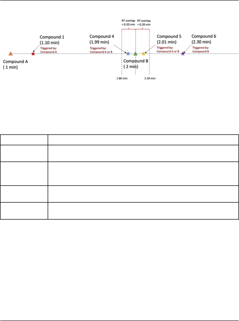
Figure A-5 RT Overlap
Triggered By
The Triggered by column shows the compound ID of the marker transition assigned to
each dependent transition. Marker transitions are automatically assigned based on user input,
including trigger selection, relative retention times, indicating elution order, and RT overlap.
Table A-1 Triggered by Column
Syntax Description
[ start of run ] Shows for the first marker transition, or for a transition that elutes before the
retention time of the first marker transition.
|| Shows for a transition that can be triggered by either its own user-defined
marker transition or the adjacent marker transition defined in the RT
overlap window.
&& Shows when a transition is triggered by multiple marker transitions
belonging to the same Group ID with the same retention time.
( ) Shows the group for multiple marker transitions with the same retention
time that belong to the same Group ID.
Group Mode
In group mode, dependent transitions are assigned to marker transitions by super group. Each
super group has at least one marker transition, and multiple dependent transitions, which will be
triggered by those marker transitions. The marker transitions must be the first eluting transitions
in the super group. If multiple marker transitions are assigned to a super group, then all of the
marker transitions must get to their trigger threshold before the dependent transitions will be
triggered.
The grouping of the marker transitions and dependent transitions into super groups is based on
a predefined analytical relationship that logically connects these compounds together, such as
precursor or metabolite, structural isomers, and protein or peptide confirmation.
Theory of Operation—Software
Software User Guide
RUO-IDV-05-9804-F
SCIEX OS Software for SCIEX Triple Quad and QTRAP
Systems
221/262

Input of retention times is optional for both the marker and dependent transitions. Transitions
without a retention time are scanned from the time that their marker transition gets to its intensity
threshold until the end of the run. Transitions with a specified retention time are scanned during
their retention time window, as in the Scheduled MRM (sMRM) algorithm.
During exploratory screening, retention times might not be known for all analytes, especially
those that are only suspected to be present in certain samples. Group mode combines retention
time window scheduling from the sMRM algorithm and super group-based triggering, which lets
the user simultaneously quantitate the typical target analyte list and opportunistically screen
for additional compounds with unknown retention times in the same injection. In addition, any
transitions that are not assigned to a super group are acquired with the sMRM algorithm.
Theory of Operation—Software
SCIEX OS Software for SCIEX Triple Quad and QTRAP
Systems
222/262
Software User Guide
RUO-IDV-05-9804-F

Figure A-6 Group Mode
Item Description
1 Early eluting marker that goes above a threshold trigger.
2 Dependent compounds that are grouped with the marker compound
Compound A, based on analytical interest.
Theory of Operation—Software
Software User Guide
RUO-IDV-05-9804-F
SCIEX OS Software for SCIEX Triple Quad and QTRAP
Systems
223/262

Item Description
3 MRM transitions from markers (Compound B and Compound C) that did
not go above their trigger thresholds. These dependent transitions are not
acquired.
Figure A-7 Method Overview (Positive and Negative Polarity)
Item
Description
1 Dependents of Compound A with specified retention times.
2 Dependents of Compound A with retention time set to zero (0).
3 Dependents of Compound B with retention time set to zero (0).
4 Dependents of Compound C with retention time set to zero (0).
Theory of Operation—Software
SCIEX OS Software for SCIEX Triple Quad and QTRAP
Systems
224/262
Software User Guide
RUO-IDV-05-9804-F

Triggered By
The Triggered by column shows the compound ID of the marker transition assigned to
each dependent transition. Marker transitions are automatically assigned based on user input,
including trigger selection and super group assignment.
Table A-2 Triggered by Column
Syntax Description
[ start of run ] Shows for a marker transition that belongs to a Super Group ID with a
retention time of zero (0).
|| Shows for a transition that can be triggered by multiple marker transitions
with a different Group ID but the same Super Group ID.
&& Shows when a transition is triggered by multiple marker transitions with the
same Group ID, retention time, and Super Group ID.
( ) Shows the group for multiple marker transitions with the same retention
time that belong to the same Group ID.
Scheduled Ionization
The Scheduled Ionization feature can be used to reduce the mass spectrometer downtime by
decreasing the risk of contamination. If this feature is enabled, then the user can specify the
period during which the Spray voltage or Nebulizer current, depending on the type of probe in
use, is set to the value specified in the method.
To use this feature, first determine the period during which the peaks of interest elute by
acquiring data without the feature enabled.
After determining the required period, enable the feature, and then set an appropriate Start time
and Stop time.
For example, for a method with a duration of 5 minutes, if the peaks of interest elute between 1.6
minutes and 3.4 minutes, then a Start time of 1.5 minutes and a Stop time of 3.5 minutes might
be used.
Decision Rules
While a batch is being processed in the Queue workspace, the software can perform select
corrective actions in response to specified analysis results. For example, if a sample fails
to meet the acceptance criteria defined in the processing method (analysis result), then the
software can be instructed to reinject the sample (corrective action).
This feature is implemented with decision rules. A decision rule consists of two main parts:
• A flagging rule, which defines the analysis result
Theory of Operation—Software
Software User Guide
RUO-IDV-05-9804-F
SCIEX OS Software for SCIEX Triple Quad and QTRAP
Systems
225/262

Flagging rules are defined in processing methods.
• A corrective action, which is applied if the processing results do not satisfy the criteria for the
analysis result
Corrective actions include the following:
• Stopping the queue
• Aborting the batch
• Injecting a different sample
• Reinjecting the flagged sample
When creating a batch, the user can activate decision rules for the batch, and then select the
decision rules to be used.
Dynamic Background Subtraction Algorithm
The Dynamic Background Subtraction algorithm improves detection of precursor ions in an
Information Dependent Acquisition (IDA) experiment. When the algorithm is activated, IDA uses
a spectrum that has been background subtracted to select the precursor ion of interest for
MS/MS analysis, instead of selecting the precursor from the survey spectrum directly. Because
this process takes place during LC analysis, the algorithm enables detection of species as their
signal increases in intensity. As a result, this algorithm focuses on detection and analysis of the
precursor ions on the rising portion of the LC peak, up to or slightly over the top of the LC peaks.
Quantitative Analysis
Quantitative analysis is used to find the concentration of a specific substance in a sample. By
analyzing an unknown sample and comparing it to standard samples, that is, samples containing
the same substance with known concentrations, the software can calculate the concentration
of the unknown sample. The process involves creating a calibration curve using the signal
response or response ratio of the standards and then calculating the concentrations of the
unknown samples. The calculated concentrations of all of the samples are added to a Results
Table.
Quantitative analysis is most commonly performed using a Multiple Reactions Monitoring (MRM)
scan. In an MRM scan, a precursor ion and a characteristic product ion are used to define
an MRM transition that is highly specific to the analyte. The MRM transition, coupled with the
retention time associated with the analyte during liquid chromatography, provides the specificity
required for quantitation.
Quantitation is accomplished through the use of validated MRM LC-MS/MS acquisition methods,
acquisition of calibration standard curves, and the subsequent integration of the peaks
associated with the compounds of interest. The calibration curve relationship between signal
response and concentration is used to determine the quantity of a particular analyte in an
unknown sample.
Theory of Operation—Software
SCIEX OS Software for SCIEX Triple Quad and QTRAP
Systems
226/262
Software User Guide
RUO-IDV-05-9804-F

Standard Addition
Standard addition can be used to determine the concentration of a compound in a sample in
which a known matrix effect prevents the use of a traditional calibration curve.
This feature allows the user to perform standard addition calculations directly in the software. If
the standard addition feature is enabled in the quantitation workflow, then the standard addition
calculation is performed during integration, and results are shown in the Results Table.
If this feature is enabled, then these regression parameters are disabled:
• Regression Type
• Weighting Type
• Automatic Outlier Removal
Enable the Standard Addition Feature
1. Open the Analytics workspace.
2. Click Process Method > New.
Tip! To edit an existing processing method, click Process Method > Edit embedded
method and then use the following steps.
3. Select the Workflow page and then select at least one workflow and the reference samples.
4. Select the Components page and then define the component names, masses, internal
standards, groups, and so on.
Tip! If the group is defined in the Components table, then the user can choose to sum
the ions in the group, even if the precursor ion and the experimental index are different
for the transitions. The summed ions are not shown in the table but are shown on the
Integration page and in the Results Table as <group name>_Sum. This feature is useful for
the quantitation of proteins and peptides.
Tip! Where the retention time of the components is not known, set the Retention Time
Mode for a mass or chemical formula to Find n peaks, where n is 1, 2, 5, 10, or all. The
software identifies the specified number of features with the greatest peak area, assigns the
appropriate retention time, and then performs a targeted peak processing workflow. When
processing is complete, the embedded method for the Results Table can be saved as a
normal targeted method.
5. Select the Integration page and then select the integration parameters for each component.
6. Click Options > Quantitate by standard addition.
This feature has specific requirements for the following batch fields:
Theory of Operation—Software
Software User Guide
RUO-IDV-05-9804-F
SCIEX OS Software for SCIEX Triple Quad and QTRAP
Systems
227/262

• Sample ID: All samples belonging to the same standard addition group must have the
same sample ID.
• Sample Type: All samples to be quantitated using standard addition must have the
sample type, Standard.
• Actual Concentration: This field must contain the known concentration of standard
added to each sample in the standard addition group. For example, for samples with no
standard added, it is 0. Data from this column is plotted as the X-axis on the Calibration
Curve.
If this feature is enabled, then the Results Table contains a new Standard Addition
Accuracy field that compares the Standard Addition Calculated Concentration for a
sample to the Standard Addition Actual Concentration.
A dynamic view of the calibration curve for a specific sample is shown in the Calibration
Curve.
Mass Reconstruction
For large molecules, a charge state spread is typically observed in an MS full scan spectrum.
The mass reconstruction feature allows the user to perform spectrum deconvolution directly
in the software, and then to perform quantitation based on the deconvoluted or zero-charged
mass peaks. If the mass reconstruction feature is enabled in the quantitation workflow, then
peak finding, spectrum deconvolution, mass peak finding, and integration are performed during
processing, and results are shown in the Results Table.
Enable Mass Reconstruction Feature
Note: Mass Reconstruction is only supported in Quantitation workflow.
Note: Mass Reconstruction is only supported for the MQ4 and Summation integration
algorithms.
Note: If Mass Reconstruction is enabled, then Options > Sum Multiple Ion is disabled.
1. Open the Analytics workspace.
2. Click Process Method > New.
Tip! To edit an existing processing method, click Process Method > Edit embedded
method and then use the following steps.
3. Select the Workflow page and then select the Quantitation workflow and the reference
samples.
4. Select the Components page.
5. Click Options > Mass Reconstruction.
Theory of Operation—Software
SCIEX OS Software for SCIEX Triple Quad and QTRAP
Systems
228/262
Software User Guide
RUO-IDV-05-9804-F

6. Add the components, typing information in the required fields.
Note: The Expected MW field is optional.
7. Click Integration to view the integration page, and review the XIC chromatograph, average
spectrum, and reconstruction spectrum, and to select the target mass.
8. Save the method.
If this feature is enabled, then the Results Table contains the following new columns:
Expected MW, MW, MW Delta (Da), MW Delta (ppm), IS Expected MW, IS MW, IS MW
Delta (Da), and IS MW Delta (ppm).
Qualitative Analysis
Qualitative analysis is the identification of a target or unknown compound. In mass spectrometry,
determining which compound is present is accomplished using mass accuracy, retention time,
isotope pattern, library searching, and formula finding. Using all of these tools together can
increase the confidence in identifying both targeted and non-targeted compounds in unknown
samples.
Retention Time
Most mass spectrometers use some type of chromatography. The retention time for a compound
is determined by injection of a known standard of the compound. Retention time can be used
to help identify target compounds in a sample. If the suspected compound is in an unknown
sample, then the closer the retention time is to the retention time of the standard, the more likely
the unknown compound can be identified. Retention times can change and must be routinely
confirmed using a known standard.
Isotope Pattern
The full scan mass spectrum from a compound in a mass spectrometer has a distinct isotope
pattern based on its molecular formula.
For the isotope pattern for morphine, refer to the following figure.
Theory of Operation—Software
Software User Guide
RUO-IDV-05-9804-F
SCIEX OS Software for SCIEX Triple Quad and QTRAP
Systems
229/262

Figure A-8 Isotope Pattern (Morphine)
This isotope pattern for imazalil is comprised of the different mass isotopes for the elements.
The isotope pattern is calculated theoretically and then compared to what was actually acquired
for the compound in the unknown. The closer the match between the theoretical and the actual
isotope pattern, the more likely it is that the compound has been identified.
Library Searching
Comparing acquired MS/MS spectra from unknown samples to a database of compounds with
reference spectra is one of the most powerful tools in qualitative analysis. Library search
algorithms compare the unknown spectra from the sample and then try to match the spectra
to the known compounds and spectra in the database. The closer the match and the higher the
reported score are, the more likely it is that the compound was identified.
The purity, fit and reverse fit are calculated as follows:
• If there is a peak at a given mass in both the (reduced) library spectrum and the (reduced)
unknown spectrum whose intensity ratio is within the limits specified by the user, the intensity
of the peak in the library spectrum is set equal to that of the unknown spectrum
• The purity is calculated as:
100.0 (UL
total
)
2
/ (U
total
•L
total
) where:
U
total
= ∑ U
m
•U
m
L
total
= ∑ L
m
•L
m
UL
total
= ∑ U
m
•L
m
Theory of Operation—Software
SCIEX OS Software for SCIEX Triple Quad and QTRAP
Systems
230/262
Software User Guide
RUO-IDV-05-9804-F

The sums include all masses where the intensities U
m
and L
m
are the square roots of the
mass-weighted, that is reduced; unknown; and library entries. The purity is guaranteed to fall
in the range between 0 to 100 and is a measure of the similarity of the library spectrum and
the unknown spectrum.
• The fit is calculated in exactly the same manner as the purity, except that only masses
which occur in the library spectrum are included in the sums. This has no effect on L
total
or
UL
total
because no terms are deleted from these sums. The fit is a measure of the degree to
which the library spectrum is contained in the unknown spectrum. A high fit and a low purity
indicates that the unknown spectrum is likely impure, but contains the library compound.
• The reverse fit is also calculated in the same manner as the purity, except that only masses
that occur in the unknown spectrum are included in the sums. The reverse fit is a measure of
the degree to which the unknown spectrum is contained in the library spectrum.
Formula Finding
Using a mass number, the formula finding algorithm tries to predict the chemical formula for the
compound, based on the MS and MS/MS spectra generated by a mass spectrometer. A high
formula finding score does not necessarily mean that the compound in the sample is the one
identified by formula finding algorithm, because several formula often match within the mass
error. Care must be taken and other confirmatory testing must be done before a compound is
identified using formula finding.
Note: It is not recommended to perform formula finding with nominal mass systems.
The formula finding algorithm uses the traffic light settings for mass accuracy. A red ppm error
earns a score of 0 and a perfect match earns a score of 100.
The MS spectrum contributes 67% to the final formula finding score and the MS/MS spectrum
contributes 33%. As a result, the ability of the formula to predict the MS mass is the primary
influence on the score. However, the matching of the MS/MS fragments also influences the
score.
The isotope pattern is used to generate the list of found formula, but it is not used to generate
the final score. Therefore a formula with the wrong isotope pattern will probably not be included
in the list.
A list of possible formulas is determined using precursor mass accuracy, isotopic pattern, and
MS/MS fragmentation. Proposed formulas are scored based on precursor mass accuracy and
average MS/MS mass accuracy of matching fragments.
Integration
In quantitative or qualitative analysis, integration refers to the generation of chromatographic
peak areas or heights for the compounds of interest. A processing method contains all of the
information needed to process the data.
Theory of Operation—Software
Software User Guide
RUO-IDV-05-9804-F
SCIEX OS Software for SCIEX Triple Quad and QTRAP
Systems
231/262

The compilation of quantitative or qualitative information for a given set of samples is called a
Results Table. Refer to Results Tables.
The software has three integration algorithms that can be used:
• MQ4: Selects a low concentration, but not the lowest concentration, standard or quality
control sample by default as the representative sample of the analytical run.
• AutoPeak: Selects a high concentration, but not saturated, standard or quality control sample
by default as the representative sample of the analytical run.
• Summation: Does not perform a normal peak search, but assumes that a peak is present
close to the expected retention time.
It is also possible to manually integrate peaks that were missed by the algorithms.
AutoPeak Integration Algorithm Parameters
The following parameters are used to identify and report the peak of interest.
For a complete list of available parameters, refer to the Help System.
• Local peak baseline: The software assesses changes to the baseline locally around the
peak as opposed to calculating the baseline with respect to the entire chromatogram.
• Linear peak baseline: The software fits a line between the points at the beginning and at
the end of that specific group of peaks as opposed to the possibility of having a non-linear
baseline below the peak.
Saturation correction: When the algorithm detects that a peak is saturated, it uses the model
to predict how the peak might look if the detector had not saturated. This causes the profile to
extend above the top of the peak to approximate the response that would have been obtained.
This can extend the linear dynamic range of calibration curves. This option is only available
when setting the overall algorithm default values and not during processing method creation or
individual peak review, because it is not useful to use this setting for only some peaks.
Minimum Signal/Noise
If the minimum signal to noise is set to seven, as shown in the left graph in the following figure,
then the peak is not reported. If the minimum signal to noise is set to two, as shown in the right
graph, then the peak is reported. This parameter does not affect integration.
Theory of Operation—Software
SCIEX OS Software for SCIEX Triple Quad and QTRAP
Systems
232/262
Software User Guide
RUO-IDV-05-9804-F
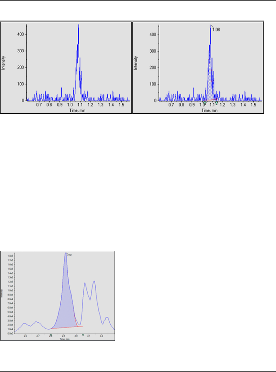
Figure A-9 S/N Threshold
Confidence Threshold
This parameter is used to filter potential peaks that are false positives. The default value is 50%,
which is usually suitable. However, the user might want to use a larger value for very noisy data
or for data for which the peak width has considerable variation from sample-to-sample.
The following two figures show how the Confidence Threshold affects the number of peaks
identified. If the Confidence Threshold is set to 50%, then the peak with a little shoulder is
identified as one peak. If the Confidence Threshold is lowered to 16%, then the SignalFinder
algorithm finds two peaks. Drag across the two peak regions to view the two peaks.
To determine which other peaks are potentially present in this single peak, and if the correct
Confidence Threshold is not known, press Ctrl and then drag across the peak region of
interest. This automatically lowers the Confidence Threshold to reveal the second peak of
interest that is not present when the Confidence Threshold is set to 50%.
Figure A-10 50% Confidence
At 16% confidence, two peaks are found. Drag across the peak area to identify the two peaks.
Theory of Operation—Software
Software User Guide
RUO-IDV-05-9804-F
SCIEX OS Software for SCIEX Triple Quad and QTRAP
Systems
233/262

Figure A-11 16% Confidence
Figure A-12 Confidence Threshold Parameter
Local versus Global Peak Baselines
The peak baseline can be local or global. If the local option is selected, then the quantitation
software assesses changes to the baseline locally. The global option uses the entire
chromatogram as the baseline.
For an example showing when the local baseline should be used, refer to the following figure.
The left graph shows a chromatogram that was properly integrated using the local baseline. The
right graph shows the same chromatogram, improperly integrated using the global baseline.
Theory of Operation—Software
SCIEX OS Software for SCIEX Triple Quad and QTRAP
Systems
234/262
Software User Guide
RUO-IDV-05-9804-F

Figure A-13 Use Global Baseline
Linear versus Non-linear Peak Baselines
The peak baseline can be set to linear or non-linear. The non-linear option estimates the
baseline under each peak. The linear option fits a line between the points at the beginning
and end of that specific group of peaks. For examples of linear and non-linear baselines for
co-eluting peaks, refer to Figure A-14 and Figure A-15. Items 1 to 4 are convolved peaks. Item 5
shows the baseline, as derived with the different options.
A non-linear baseline is recommended for multiple peaks. For a single peak, the difference
between the linear and non-linear baseline is insignificant.
Theory of Operation—Software
Software User Guide
RUO-IDV-05-9804-F
SCIEX OS Software for SCIEX Triple Quad and QTRAP
Systems
235/262

Figure A-14 Example of a Linear Baseline
Theory of Operation—Software
SCIEX OS Software for SCIEX Triple Quad and QTRAP
Systems
236/262
Software User Guide
RUO-IDV-05-9804-F

Figure A-15 Example of a Non-linear Baseline
MQ4 Integration Algorithm Parameters
The following parameters are used to identify and report the peak of interest. For a complete list
of available parameters, refer to the Help System.
Noise Percentage
This parameter is used to estimate the noise level in the chromatograms. The specified
percentage of the data points with the smallest intensity are assumed to be noise.
Typical values range from 20% to 60%. If small peaks in the presence of larger peaks are
not being found, then the noise percentage should be lowered. The following figure shows an
example of a small peak in the presence of an extremely large peak. This peak is not found
when the noise percentage is set to 90% but is found when the noise percentage is set to 40%.
Theory of Operation—Software
Software User Guide
RUO-IDV-05-9804-F
SCIEX OS Software for SCIEX Triple Quad and QTRAP
Systems
237/262

Figure A-16 Peak of Interest
In the following figure, the left graph shows the noise percentage set to 40%. The right graph is
set to 90%.
Figure A-17 Noise Levels
Baseline Subtract Window
After smoothing, but before other processing, chromatograms are baseline subtracted to remove
humps in the data. For each data point, the baseline is calculated using the data points on both
the left and right side of the current point with minimum intensity, within the subtraction window.
The exact value of this parameter is not critical, provided that it is set at least a few times larger
than the expected peak width.
In the following figure, the left graph shows the baseline subtraction window set to 0.1 minutes
and the right graph shows the baseline subtraction window set to 1 minute.
Theory of Operation—Software
SCIEX OS Software for SCIEX Triple Quad and QTRAP
Systems
238/262
Software User Guide
RUO-IDV-05-9804-F

Figure A-18 Baseline Subtraction Window
Peak Splitting
This parameter controls whether a potentially noisy peak is found as one single peak or as two
or more separate peaks. If the dip between two potential peaks is less than the specified value,
then a single peak is found. Otherwise, two peaks are found.
Setting this parameter to a large value will prevent noisy peaks from being split and found as
two separate peaks. However, a smaller value needs to be used if there are two closely eluting
(overlapping) distinct peaks.
In the following figure, the left graph shows Peak Splitting set to two points. The right graph
shows Peak Splitting set to three points.
Figure A-19 Peak Splitting
Theory of Operation—Software
Software User Guide
RUO-IDV-05-9804-F
SCIEX OS Software for SCIEX Triple Quad and QTRAP
Systems
239/262

Regression
The area or height of the analyte peaks is plotted against the known concentrations in the
Calibration Curve and Metric Plot. Subsequently, a line is fitted to the points. This regression line
is used to calculate the concentration of the unknown samples.
Regression Equations
This section describes the equations used to calculate the regression curves. In the following
equations, x represents the analyte concentration for standard samples and y represents the
corresponding peak area or height. The exact variables used for the regression depend on
whether an internal standard is being used and whether the peak area or the peak height is used
as shown in the following table.
Table A-3 Regression Variables
Internal
Standard Used?
Area Used? x y
Yes Yes C
a
/ C
is
/ DF A
a
/ A
is
Yes No C
a
/ C
is
/ DF H
a
/ H
is
No Yes C
a
/ DF A
a
No No C
a
/ DF H
a
where:
• C
a
= actual analyte concentration
• C
is
= internal standard concentration
• DF = dilution factor
• A
a
= analyte peak area
• A
is
= internal standard peak area
• H
a
= analyte peak height
• H
is
= internal standard peak height
Weighting Types
The following table shows how the weighting factor (w) is calculated for each of the seven
weighting types.
Theory of Operation—Software
SCIEX OS Software for SCIEX Triple Quad and QTRAP
Systems
240/262
Software User Guide
RUO-IDV-05-9804-F

Table A-4 Weighting Types
Weighting Type Weight (w)
None Always 1.0.
1 / x If |x| < 10
-5
, then w = 10
5
. Otherwise, w = 1 / |x|.
1 / x
2
If |x| < 10
-5
, then w = 10
10
. Otherwise, w = 1 / x
2
.
1 / y If |y| < 10
-8
, then w = 10
8
. Otherwise, w = 1 / |y|.
1 / y
2
If |y| < 10
-8
, then w = 10
16
. Otherwise, w = 1 / y
2
.
ln (x) If x < 0, then an error is generated. If x < 10
–5
, then w = ln 10
5
. Otherwise,
w = |ln (x)|.
ln (y) If y < 0, then an error is generated. If y < 10
–8
, then w = ln 10
8
. Otherwise,
w = |ln (y)|.
Correlation Coefficient
In the regression equations, x, y, and w are as defined previously. All sums are calculated over
all standard samples, with the exception of those standard samples that are marked as not used.
The correlation coefficient is calculated as:
where:
•
• y
c
= Y-value calculated using the appropriate equation for the regression type
•
Regression Types
In the Analytics workspace, the following types of regression are available:
• Mean (Metric Plot pane only)
• Median (Metric Plot pane only)
• Linear (y = mx + b)
• Linear through Zero (y = mx)
• Mean Response Factor
• Quadratic (y = a
2
+ bx + c)
Theory of Operation—Software
Software User Guide
RUO-IDV-05-9804-F
SCIEX OS Software for SCIEX Triple Quad and QTRAP
Systems
241/262

• Power
• Wagner
• Hill
Note: The Remove outliers automatically from the calibration curve option on the
Regression Options dialog in the Calibration Curve pane automatically applies the automatic
outlier removal rules to the selected components of interest. Refer to the Help.
Linear
The linear calibration equation is:
y = mx + b
The slope and intercept are calculated as:
where:
Linear Through Zero
The linear through zero calibration equation is:
y = mx
The slope is calculated as:
Mean Response Factor
The mean response factor calibration is:
y = mx
This is the same equation as for the linear though zero calibration. However, the slope is
calculated differently as:
Theory of Operation—Software
SCIEX OS Software for SCIEX Triple Quad and QTRAP
Systems
242/262
Software User Guide
RUO-IDV-05-9804-F

and the standard deviation of the response factor as:
where:
Note: Points whose x value is zero are excluded from the sums.
If there is some linearity and some curvature in the line of points, then use power regression
instead of linear or quadratic regression to produce a line somewhere between these fits.
Quadratic
The quadratic calibration equation is:
y = a
2
x
2
+ a
1
x + a
0
The polynomial co-efficients are calculated as:
a
2
= (b
2
/b
0
- b
5
/b
3
) / (b
1
/b
0
- b
4
/b
3
)
a
1
= b
5
/b
3
- a
2
b
4
/b
3
where:
Power
The power function calibration equation is:
Theory of Operation—Software
Software User Guide
RUO-IDV-05-9804-F
SCIEX OS Software for SCIEX Triple Quad and QTRAP
Systems
243/262

y = ax
p
The equations for the linear calibration are used as described above to calculate the slope (m)
and intercept (b), except that x in those equations is replaced by ln x and y is replaced by ln y.
When this is done, a and p are calculated as:
a = e
b
p = m
If any of the x- or y-values are negative or zero, then an error is reported.
Wagner
The Wagner calibration equation is:
ln y = a
2
(ln x)
2
+ a
1
(ln x) + a
0
The equations for the quadratic calibration are used as described above to calculate a
0
, a
1
, and
a
2
, except that x in those equations is replaced by ln x and y is replaced by ln y.
If any of the x- or y-values are negative or zero, then an error is reported.
Hill
The Hill calibration equation is:
y = (a + bx
n
) / (c + x
n
)
It is not possible to provide an analytical function for solving for a, b, c, and n. Instead, the
co-efficients are determined using the iterative Levenberg-Marquardt method.
Automatic Removal of Outliers
An optional feature allows the software to remove outliers from the calibration curve
automatically. This time-saving feature is useful for applications with many compounds with
different linear range and sensitivity.
When this feature is enabled, the software iteratively surveys all data points to identify a
starting range, consisting of four consecutive points, that provides the best linear regression and
satisfies user-specified rules for outlier removal. The algorithm calculates multiple regressions
for all permutations of the starting points. It considers all valid regressions that satisfy the
user-specified rules and takes all of them through the expansion sequence. For all of the valid
starting ranges, the success of each expansion depends on the total number of used points, the
range of the used levels, and the point with the worst absolute accuracy error in the regression
before and after the expansion. The regression that spans the largest range and satisfies the
rules is the "winning" regression.
Theory of Operation—Software
SCIEX OS Software for SCIEX Triple Quad and QTRAP
Systems
244/262
Software User Guide
RUO-IDV-05-9804-F

Note: If four data points are not available, then the software will use three. The algorithm will not
be applied if less than three points are available.
The rules for automatic removal of outliers are defined in the processing method, and include the
following:
• Minimum correlation coefficient (r)
Note: This option uses the correlation coefficient, not the coefficient of determination (r
2
).
• Maximum allowed accuracy error for standard replicates at the lower level of quantitation
(LLOQ)
• Maximum allowed accuracy error for standards above the LLOQ
• Maximum percentage coefficient of variation (CV) for multiple replicates of a standard at
LLOQ
Note: If %CV is greater than the specified value, then the algorithm removes replicates in
decreasing order of accuracy error until the %CV of remaining replicates is less than this
value.
• Maximum percentage CV for multiple replicates of a standard at all levels above the LLOQ
Note: If %CV is greater than the specified value, then the algorithm removes replicates in
decreasing order of accuracy error until the %CV of remaining replicates is less than this
value.
• Whether the specified total number of outliers excludes outliers below the LLOQ and upper
limit of quantitation (ULOQ)
• Maximum number of outliers that can be removed for a concentration level
• Total number of outliers that can be removed from a calibration curve
Note: This algorithm is applied to all standards, including those manually excluded.
Note: If the number of replicates that is used to produce the regression is different for each
standard level, then the automatic outlier removal feature does not work perfectly and must only
be used as a starting point. Review each calibration curve manually.
Tip! Make sure that the tolerance thresholds for standards accuracy in the Acceptance Criteria
for the processing method match the thresholds in the Rules for Automatically Removing
Outliers for Calibration Standards dialog.
Theory of Operation—Software
Software User Guide
RUO-IDV-05-9804-F
SCIEX OS Software for SCIEX Triple Quad and QTRAP
Systems
245/262

Results Tables
A Results Table is a compilation of the quantitative and qualitative information associated with
a set of samples. It includes the calculations for concentration and accuracy determined as a
result of interpolating the standard calibration curve. The library search results, formula finding
results, and other qualitative analysis results are also available in the Results Table. Area,
height, and other numerical characteristics can be shown. The number and type of columns in
the Results Tables can be edited for simplified viewing.
Calibration Curves
A calibration curve, also know as a standard concentration curve, is a method for determining
the concentration of a substance in an unknown sample by comparing the unknown sample to
a set of standard samples of known concentration. The calibration curve is a plot of how the
instrument responds (the analytical signal) to changes in the concentration of the analyte (the
substance to be measured). The operator prepares a series of standards across a range of
concentrations near the expected concentration of the analyte in the unknown sample.
Calibration standards are used to build calibration curves. Incorrect readings or missing readings
on some of the calibration samples might indicate issues with the analytical run. Follow
acceptable methods found in literature and regulatory agency guidances to create a calibration
curve. Examples of good practices in the preparation of calibration curves include:
• Preparing calibration standards in a blank matrix in which the analyte is to be measured.
• Generating a calibration curve for each analyte to be measured.
• Making sure of the coverage of the expected concentration range of the analyte, including
typical and atypical specimens.
• Using six to eight standards to generate the curve.
This is not a comprehensive list and other guidances should be used in determining the best
practice in developing a calibration curve for the laboratory.
Note: In some analytical runs, single-point calibration standards are used. Single-point
calibrations are performed using a matrix blank sample and a single standard concentration. The
relationship between instrument response and analyte concentration is determined by the line
created by these two points. Both the acquisition and processing methods should be validated
before being accepted for their intended use.
Signal to Noise Ratio
When performing quantitative mass spectrometry data processing, it is important to determine
whether a given peak is significant or not, where significant typically means exceeding
background noise.
Theory of Operation—Software
SCIEX OS Software for SCIEX Triple Quad and QTRAP
Systems
246/262
Software User Guide
RUO-IDV-05-9804-F

Relative Noise and Signal-to-Noise Calculations
Usually the peak height is compared to background noise measured in a peak-free region where
the noise is typically estimated as either one or three times the standard deviation of the data
points in this range. This approach is less than ideal for the following reasons:
• It is subjective, as the noise region is selected manually.
• A background region without a peak might not exist or the region might be too narrow for an
accurate estimate of the noise.
• The noise at the peak position might be quite different from that in the selected noise region.
• The factor of ‘one or three’ is also subjective and different authorities have different
recommendations.
• The apparent noise can be altered if the data have been pre-processed. For example,
smoothed, or thresholded.
The concept of Relative Noise (Rn), makes it easy to develop a simple method to calculate the
expected noise at any point in the data, for comparison with the measured signal. This is a
robust, objective metric that can be used to calculate signal-to-noise (S/N) and to evaluate and
compare instrument and assay performance. There are many applications of the relative noise
concept, one of which is the calculation of S/N.
The basic algorithm works as follows:
1. Devise a noise model that will allow the user to calculate the expected noise at any point in
the data record, given the level of the underlying signal at that point.
The noise model can be determined from theoretical considerations or it can be modeled
from real measurements for a particular system. For pulse counting detectors, the standard
deviation of a signal, and therefore the expected noise, is proportional to the square root
of the signal and therefore varies with the signal. In other systems there will be a constant
‘white noise’ component, possibly combined with an intensity-dependent component.
2. Estimate the underlying signal from the measured signal.
This task can be achieved in many ways, but the simplest is to generate a smoothed version
of the data. Refer to the figure: Figure A-20.
Theory of Operation—Software
Software User Guide
RUO-IDV-05-9804-F
SCIEX OS Software for SCIEX Triple Quad and QTRAP
Systems
247/262

Figure A-20 Overlay of Raw and Smoothed Data
3. Measure the actual noise across the data using all points, both peaks and background.
This is achieved by subtracting the underlying signal estimate from the measured signal at
each point in the data where the smoothed signal has been subtracted from the original.
The result is known as the delta noise. The range of the delta noise is reasonably constant,
except where there are large peaks, because the noise is dependent on the signal and
therefore greater where the signal is larger. Refer to the figure: Figure A-21.
Figure A-21 Plot of the Delta Noise Values of Each Data Point
4. At each data point, calculate the ratio of the measured noise to the expected noise.
That is, at every data point, divide the noise measured in step 3 by the value that the noise
model predicts, in this case the square root of the intensity. If the noise model is good, then
the sofware generates a series of values that mostly remain bounded by some limits. Refer
to the following figure. This figure also shows the plot of
Note: This step reduces the large variation in the delta noise and results in a well
constrained set of values.
Theory of Operation—Software
SCIEX OS Software for SCIEX Triple Quad and QTRAP
Systems
248/262
Software User Guide
RUO-IDV-05-9804-F

Figure A-22 Noise Model
5. Calculate the standard deviation of the ratio values. This is the Rn, an estimate of the most
likely relationship between the actual delta noise and that predicted by the model. In the
preceding figure, this results in a value of 9.5.
The following figure shows an example of how relative noise can be used to calculate S/N.
Figure A-23 Overlay of Raw Data, Underlying Signal Estimates, and Baseline
Estimates
As described previously:
In this example:
Theory of Operation—Software
Software User Guide
RUO-IDV-05-9804-F
SCIEX OS Software for SCIEX Triple Quad and QTRAP
Systems
249/262

If the apex of the peak is used as the signal, then the S/N is 34 (4900/145) and if the height of
the smoothed signal is used, then the S/N is 22 (3150/145).
When reporting the S/N, the MQ4 integration algorithm uses the procedure described here and
the peak apex as the signal. Because the AutoPeak integration algorithm is fitting a model to
the peak, it uses the height of the fitted profile. This results in a smaller reported S/N. However,
it is a more accurate value because it is less affected by possible noise spikes. The AutoPeak
integration algorithm also has a more sophisticated approach to baseline estimation, so for these
two reasons, the S/N values reported by the two algorithms are not identical, although they will
usually be similar.
In summary, compared to the usual approach of estimating the noise as the standard deviation
of a background region, the relative noise approach to calculating S/N has the following
advantages:
• It is much less subjective because a background region need not be selected manually.
• An accurate S/N can be predicted even if no peak-free regions exist in the chromatogram.
• For the AutoPeak and Summation integration algorithms, the baseline, and therefore the
noise, is estimated near the peak of interest. For the MQ4 integration algorithm, the baseline
is the intensity of the data point at the user-specified noise percentage. For example, if
the user-specified noise percentage is 40%, and there are 100 data points, then the MQ4
integration algorithm sorts the data points from the smallest to largest intensity, and uses the
intensity of the data point with the fortieth-smallest intensity.
This can make a large difference to the reported S/N value because the background region
selected for the usual approach might be much quieter than the background near the peak.
As described previously, the S/N calculated using the Relative Noise approach might give
smaller values than the usual approach. However, they are more accurate and useful values.
Refer to Figure A-23.
To make the Signal / Noise column visible in the Results Table, refer to Customize the Results
Table.
Note on Signal-to-Noise when Using the AutoPeak Integration
Algorithm
Because the AutoPeak integration algorithm calculates signal-to-noise more accurately (and
thefore more accurately predicts CVs), if the 1-sigma signal-to-noise approach is used, then
consider decreasing the minimum acceptable signal-to-noise value on any standard operating
procedures (SOPs), based on empirical data from the laboratory.
Signal-to-Noise Using Peak-to-Peak
If this signal-to-noise algorithm is used, then the software calculates the signal-to-noise ratio by
taking the standard deviation of all of the chromatographic data points between the specified
background start and background end times. The software calculates the signal-to-noise ratio for
the active chromatogram, subtracts the average background signal from the selected peak, and
Theory of Operation—Software
SCIEX OS Software for SCIEX Triple Quad and QTRAP
Systems
250/262
Software User Guide
RUO-IDV-05-9804-F

then divides the subtracted signal by the peak-to-peak noise level. It then differentiates the noise
and peak regions based on the maximum intensities of each region. Upon completion, the active
chromatogram is labeled with the signal-to-noise ratio.
Signal-to-Noise Using Standard Deviation
When this signal-to-noise algorithm is used, the software calculates the signal-to-noise ratio of
chromatographic peaks and labels them. This algorithm requires that two regions be selected on
the chromatogram:
• The noise region
• The peak of interest
The software then determines which region contains the peak and which region contains the
noise, based on maximum intensities in each selection. It subtracts the average background
signal intensity from the peak signal intensity and then divides the subtracted signal by a
user-specified factor multiplied by the standard deviation of the noise region.
Define Noise Regions
Use this procedure to define noise regions if the standard deviation or peak-to-peak algorithm is
used.
Note: Only one signal-to-noise algorithm can be used in a Results Table. To apply a different
signal-to-noise algorithm to the data, change the project defaults and then create a new Results
Table.
1. In the project default settings, select the Standard Deviation or Peak-to-Peak signal-to-
noise algorithm.
Tip! To open the project default settings, click Projects > Project default settings.
2. Create a processing method.
3. On the Integration page, click Options > Show Noise Regions.
4. (If required) Use the mouse to adjust the noise region.
Note: The noise region must be set for each transition.
5. Process the data.
6. In the Peak Review pane, click Options > Show Noise Regions.
7. (If required) Use the mouse to adjust the noise region.
Theory of Operation—Software
Software User Guide
RUO-IDV-05-9804-F
SCIEX OS Software for SCIEX Triple Quad and QTRAP
Systems
251/262

Calculated Columns
Calculated columns are formulas that result in new custom columns being added to a Results
Table. After a formula is created and the data is processed (or reprocessed), the results of the
formula are shown in a new custom column.
Navigating the Calculated Column Interface
Calculated columns are created in a processing method. They can be imported and exported as
frml files for later use or sharing.
The following figure shows the interface for the formula editor.
Figure A-24 Calculated Columns UI
Item Description
1 The Calculated Columns step in the workflow of the processing method.
Click to open the Calculated Columns page. Then click Add Formula (not
shown).
2 The Formula name field. Type a name for the formula.
Note: The formula name cannot contain the names of functions on the
calculator, square brackets, or rounded brackets.
3
The Formula field.
Theory of Operation—Software
SCIEX OS Software for SCIEX Triple Quad and QTRAP
Systems
252/262
Software User Guide
RUO-IDV-05-9804-F
Item Description
4 A calculator containing commonly used functions and operators. The
following additional operators can be typed in the formula field:
• > (greater than)
• >= (greater than or equal to)
• < (less than)
• <= (less than or equal to)
• != (not equal to)
For more information about these operators and functions, refer to the Help
System.
5 Available regression parameters and Results Table columns.
Note: This list is not available in qsession tables.
6 The Treat resulting text values as menu allows the user to configure how
text entries are handled. This option is important in Results Table columns
that may contain both numeric and text outputs.
For example, calculated concentration columns can contain numeric values
along with non-numeric values such as N/A, degenerate, and infinity.
Note: When the user starts to type a formula that uses an array of samples, a sample selection
item becomes available.
Simple Extraction of Non-default Information
The calculated columns feature allows users to show information that is not available by default
in Results Tables.
For example, to show R
2
as a column in the Results Table, the user can create a formula equal
to R
2
.
Theory of Operation—Software
Software User Guide
RUO-IDV-05-9804-F
SCIEX OS Software for SCIEX Triple Quad and QTRAP
Systems
253/262

Figure A-25 Creating a Custom Column with Calculated Columns
Simple Arithmetic
Simple formulas can be created to perform basic mathematical operations.
Example: R
2
[r]*[r]
In this example, the R
2
value is reproduced by using the multiplication operator (*) to multiply the
R-value by itself.
Example: Points Per Second Collected
[Points Across Baseline]/(([End Time]-[Start Time])*60)
In this example, the points across the baseline are divided by the seconds from the beginning to
the end of an integrated chromatographic peak. This formula uses the division (/), multiplication
(*) and subtraction (–) operators.
Theory of Operation—Software
SCIEX OS Software for SCIEX Triple Quad and QTRAP
Systems
254/262
Software User Guide
RUO-IDV-05-9804-F

More Complex Functions
Many other functions and control structures exist. Some common ones are MEAN(), MAX(), and
MIN(), and are shown in the calculator under the formula bar.
For a complete list of syntax details, operators, and functions, refer to the Help System.
Example: MEAN([Area]) for Standards
When using a function that operates on all values, the user can select the samples to be
included in the calculation.
Figure A-26 Obtaining the Mean of the Peak Area of Standard Samples Only
Example: Combining Functions
Simple arithmetic and more complex functions can be combined. For example, to calculate the
mean points per second collected, use the following formula:
MEAN([Points Across Baseline]/(([End Time]-[Start Time])*60))
IF Statements
The IF function performs a logical test and returns one value for a true result, and another for
a false result. Nested IF functions can be used to test more than one condition. The IF function
can be combined with other logical functions such as and and or to extend a logical test.
Theory of Operation—Software
Software User Guide
RUO-IDV-05-9804-F
SCIEX OS Software for SCIEX Triple Quad and QTRAP
Systems
255/262

Note: "&&" and "||" can be used for and and or, respectively. The and and or operators must be
surrounded by spaces, but the && and || operators do not need to be.
The basic IF statement syntax is as follows:
if(<condition>;<value if true>;<value if false>)
• <condition> is a value or logical expression that can be evaluated as true or false.
• <value if true> is a value to be returned and shown in the corresponding Results Table
column when <condition> evaluates to true.
• <value if false> is a value to be returned and shown in the corresponding Results Table
column when <condition> evaluates to false.
Note: The IF function symbol can be selected from the calculator, typed, or copied from another
source. It can be used in if or IF syntax.
The IF function allows other numeric functions, such as MEAN, STDEV, and so on, to be used
within the formula as well, in the <condition>, <value if true>, or <value if false> expressions.
Example: <condition>
Some examples of a <condition> include:
[Peak Area]>5000
[Component Name]='Analyte 1'
[Retention Time]> 1 and [Retention Time]<2
Example: <value if true> and <value if false>
<value if true> and <value if false> can be either numeric or text.
if([Retention Time]> 1 and [Retention Time]<2; '1-2 min RT window';
'not applicable')
Example: Mean Value for Internal Standard Area
In this example, the mean value of the internal standard (IS) area is calculated across the
desired samples and compared to a value of 1e6. The mean IS area value is shown in the
corresponding Results Table column if MEAN ([IS Area]) is greater than 1e6, that is, if the
Theory of Operation—Software
SCIEX OS Software for SCIEX Triple Quad and QTRAP
Systems
256/262
Software User Guide
RUO-IDV-05-9804-F

<condition> is true. If MEAN ([IS Area]) is less than 1e6, that is, if the <condition> is false, then
the Results Table column contains Review IS performance, the <value if false>.
IF(MEAN([IS Area])>=1e6;'MEAN([IS Area])';'Review IS performance')
Note: Only IF functions can contain multiple calculations.
Treat Resulting Text Values As
The Treat resulting text values as option determines how text is interpreted in a custom
Results Table column that contains either text or a combination of numbers and text. For
example, the Sample Type column contains only text, the Precursor Mass column contains
only numeric values, and the Calculated Concentration column might contain both numeric
values and text.
Depending on the functions used in a formula, the Treat resulting text values as option
enables specific interpretation of the text values in the column on which the calculation is based.
The available options include:
• Zero
• Ignore (blank)
• Error (N/A)
• Original text
Note: For more information about these options, refer to the Help System.
If calculations are based on the COUNT, MAX, STDEV, SUM, MIN, MEDIAN, GET,
GETGROUP, SLOPE, INTERCEPT, MAD, or GETSTAT functions, then the recommended
options are Zero, Ignore (blank), or Error (N/A). These options are also recommended in IF
statements when the formula contains columns that are expected to have numeric values.
Original text is the recommended option in IF statements where components of the
<condition>, <value if true>, and <value if false> expressions might be both numeric and text,
especially when additional functions are used.
Note: In IF statements with more than one <condition>, failure to evaluate even one <condition>
results in a <value if false> output in the custom results table column.
Example
In this example, the columns used in the formula might contain both text and numeric values.
Therefore, the Original text option is recommended.
IF([Sample Type]='Unknown'&&(GET([Calculated Concentration];
'Analyte 1')+GET([Calculated Concentration];'Analyte 2'))<=15;
Theory of Operation—Software
Software User Guide
RUO-IDV-05-9804-F
SCIEX OS Software for SCIEX Triple Quad and QTRAP
Systems
257/262

'Low Range';IF([Sample Type]='Unknown'&&(GET([Calculated
Concentration]
;'Analyte 1')+GET([Calculated Concentration];'Analyte 2'))
<=65;'Normal Range';'Over normal range'))
This IF formula contains both the Sample Type and Calculated Concentration columns.
Values in the Sample Type column should be treated as Original text. For the Calculated
Concentration column, it might be necessary to treat non-numeric values such as <0 and
Degenerate as Zero.
Because non-numeric values must be treated differently, we recommend that the user split the
formula into multiple smaller formulas, for finer control of non-numeric values.
Theory of Operation—Software
SCIEX OS Software for SCIEX Triple Quad and QTRAP
Systems
258/262
Software User Guide
RUO-IDV-05-9804-F

Exact Masses and Chemical
Formulas
B
PPG
Table B-1 contains the exact monoisotopic masses and charged species (positive and negative)
observed with the PPG (polypropylene glycol) calibration solutions. The masses and ions were
calculated using the formula M = H[OC
3
H
6
]
n
OH, while the positive ion MSMS fragments used
the formula, [OC
3
H
6
]
n
(H
+
). In all calculations, H = 1.007825, O = 15.99491, C = 12.00000, and N
= 14.00307.
Note: When performing calibrations with the PPG solutions, use the correct isotope peak.
Table B-1 PPG Exact Masses
n Exact Mass (M) (M + NH
4
)
+
MSMS
Fragments
(M + NH
4
)
2+
(M + COOH)
–
1 76.05242 94.08624 59.04914 56.06003 121.05061
2 134.09428 152.12810 117.09100 85.08096 179.09247
3 192.13614 210.16996 175.13286 114.10189 237.13433
4 250.17800 268.21182 233.17472 143.12282 295.17619
5 308.21986 326.25368 291.21658 172.14375 353.21805
6 366.26172 384.29554 349.25844 201.16468 411.25991
7 424.30358 442.33740 407.30030 230.18561 469.30177
8 482.34544 500.37926 465.34216 259.20654 527.34363
9 540.38730 558.42112 523.38402 288.22747 585.38549
10 598.42916 616.46298 581.42588 317.24840 643.42735
11 656.47102 674.50484 639.46774 346.26933 701.46921
12 714.51288 732.54670 697.50960 375.29026 759.51107
13 772.55474 790.58856 755.55146 404.31119 817.55293
14 830.59660 848.63042 813.59332 433.33212 875.59479
15 888.63846 906.67228 871.63518 462.35305 933.63665
16 946.68032 964.71414 929.67704 491.37398 991.67851
Exact Masses and Chemical Formulas
Software User Guide
RUO-IDV-05-9804-F
SCIEX OS Software for SCIEX Triple Quad and QTRAP
Systems
259/262

Table B-1 PPG Exact Masses (continued)
n Exact Mass (M) (M + NH
4
)
+
MSMS
Fragments
(M + NH
4
)
2+
(M + COOH)
–
17 1004.72218 1022.75600 987.71890 520.39491 1049.72037
18 1062.76404 1080.79786 1045.76076 549.41584 1107.76223
19 1120.80590 1138.83972 1103.80262 578.43677 1165.80409
20 1178.84776 1196.88158 1161.84448 607.45770 1223.84595
21 1236.88962 1254.92344 1219.88634 636.47863 1281.88781
22 1294.93148 1312.96530 1277.92820 665.49956 1339.92967
Reserpine
Table B-2 Reserpine Exact Masses (C
33
H
40
N
2
O
9
)
Description Mass
Molecular Ion C
33
H
41
N
2
O
9
609.28066
Fragment C
23
H
30
NO
8
448.19659
Fragment C
23
H
29
N
2
O
4
397.21218
Fragment C
22
H
25
N
2
O
3
365.18597
Fragment C
13
H
18
NO
3
236.12812
Fragment C
10
H
11
O
4
195.06519
Fragment C
11
H
12
NO 174.09134
Exact Masses and Chemical Formulas
SCIEX OS Software for SCIEX Triple Quad and QTRAP
Systems
260/262
Software User Guide
RUO-IDV-05-9804-F

Contact Us
Customer Training
• In North America: NA.CustomerT[email protected]
• In Europe: Europe.CustomerT[email protected]
• Outside the EU and North America, visit sciex.com/education for contact information.
Online Learning Center
• SCIEX Now Learning Hub
SCIEX Support
SCIEX and its representatives maintain a staff of fully-trained service and technical specialists
located throughout the world. They can answer questions about the system or any technical
issues that might arise. For more information, visit the SCIEX website at sciex.com or contact us
in one of the following ways:
• sciex.com/contact-us
• sciex.com/request-support
CyberSecurity
For the latest guidance on cybersecurity for SCIEX products, visit sciex.com/productsecurity.
Documentation
This version of the document supercedes all previous versions of this document.
To view this document electronically, Adobe Acrobat Reader is required. To download the latest
version, go to https://get.adobe.com/reader.
To find software product documentation, refer to the release notes or software installation guide
that comes with the software.
To find hardware product documentation, refer to the documentation DVD for the system or
component.
The latest versions of the documentation are available on the SCIEX website, at sciex.com/
customer-documents.
Contact Us
Software User Guide
RUO-IDV-05-9804-F
SCIEX OS Software for SCIEX Triple Quad and QTRAP
Systems
261/262

