
NASA/TM—1998-112217
Aiding Vertical Guidance Understanding
Michael Feary, Daniel McCrobie, Martin Alkin, Lance Sherry, Peter Polson,
Everett Palmer, and Noreen McQuinn
February 1998
Since its founding, NASA has been dedicated to
the advancement of aeronautics and space science.
The NASA Scientific and Technical Information
(STI) Program Office plays a key part in helping
NASA maintain this important role.
The NASA STI Program Office is operated by
Langley Research Center, the Lead Center for
NASA’s scientific and technical information. The
NASA STI Program Office provides access to the
NASA STI Database, the largest collection of
aeronautical and space science STI in the world.
The Program Office is also NASA’s institutional
mechanism for disseminating the results of its
research and development activities. These results
are published by NASA in the NASA STI Report
Series, which includes the following report types:
• TECHNICAL PUBLICATION. Reports of
completed research or a major significant phase
of research that present the results of NASA
programs and include extensive data or theoreti-
cal analysis. Includes compilations of significant
scientific and technical data and information
deemed to be of continuing reference value.
NASA’s counterpart of peer-reviewed formal
professional papers but has less stringent
limitations on manuscript length and extent of
graphic presentations.
• TECHNICAL MEMORANDUM. Scientific and
technical findings that are preliminary or of
specialized interest, e.g., quick release reports,
working papers, and bibliographies that contain
minimal annotation. Does not contain extensive
analysis.
• CONTRACTOR REPORT. Scientific and
technical findings by NASA-sponsored contrac-
tors and grantees.
The NASA STI Program Office . . . in Profile
• CONFERENCE PUBLICATION. Collected
papers from scientific and technical confer-
ences, symposia, seminars, or other meetings
sponsored or cosponsored by NASA.
• SPECIAL PUBLICATION. Scientific, technical,
or historical information from NASA programs,
projects, and missions, often concerned with
subjects having substantial public interest.
• TECHNICAL TRANSLATION.
English-language translations of foreign scien-
tific and technical material pertinent to NASA’s
mission.
Specialized services that complement the STI
Program Office’s diverse offerings include creating
custom thesauri, building customized databases,
organizing and publishing research results . . . even
providing videos.
For more information about the NASA STI Pro-
gram Office, see the following:
• Access the NASA STI Program Home Page at
http://www.sti.nasa.gov
• E-mail your question via the Internet to
• Fax your question to the NASA Access Help
Desk at (301) 621-0134
• Telephone the NASA Access Help Desk at
(301) 621-0390
• Write to:
NASA Access Help Desk
NASA Center for AeroSpace Information
800 Elkridge Landing Road
Linthicum Heights, MD 21090-2934

NASA/TM—1998-112217
Aiding Vertical Guidance Understanding
Michael Feary, San Jose State University, San Jose, California
Daniel McCrobie, Honeywell Inc., Phoenix, Arizona
Martin Alkin, Federal Express Inc., Memphis, Tennessee
Lance Sherry, Honeywell Inc., Phoenix, Arizona
Peter Polson, University of Colorado, Boulder, Colorado
Everett Palmer, Ames Research Center, Moffett Field, California
Noreen McQuinn, Boeing–Douglas Products Division, Long Beach, California
February 1998
National Aeronautics and
Space Administration
Ames Research Center
Moffett Field, California 93035-1000
NASA Center for AeroSpace Information National Technical Information Service
800 Elkridge Landing Road 5285 Port Royal Road
Linthicum Heights, MD 21090-2934 Springfield, VA 22161
Pricc Code: A 17 Price Code: A10
Available from:
Acknowledgments
Thanks to the following people for their help in performing this study.
Joe Jackson (Honeywell) for advice and management support.
Pankaj Godiwala (Honeywell) for help with the FMS and programming support.
Kevin Jordan (San Jose State University) for advice and guidance.
Joseph Cicinelli (Honeywell) for help in running the study.
Bob Geiger (Boeing) for simulator support and flexibility in scheduling.
Mark Willburger (Boeing) for help in running the study and rewiring the FTD.
Captain Ed Gorman (Honeywell) for initial review of the training and scenario.
Gary Bisgaard (Honeywell) for reprogramming and testing the DEU.
Captain James Ward (FedEx) for support with pilots and resources.
Captain Warren Travis (FedEx) for support with training materials and pilots.
Captain Rudolf Bornhauser (Swissair) for cooperation with pilots.
Captain Mike Padron (FedEx) for support and review of the tutor.
iii
CONTENTS
ACRONYMS...................................................................................................................................................................................................................v
SUMMARY......................................................................................................................................................................................................................1
INTRODUCTION...........................................................................................................................................................................................................1
Automation Surprises...................................................................................................................................................................................................2
Pilot Training in Avionics.........................................................................................................................................................................................4
PART 1—SURVEY......................................................................................................................................................................................................5
Survey Methods..............................................................................................................................................................................................................5
Survey Participants.......................................................................................................................................................................................................6
Survey Results................................................................................................................................................................................................................6
Rating Scales..................................................................................................................................... 6
Open-Ended Comments....................................................................................................................... 7
Implications......................................................................................................................................................................................................................8
PART 2—EXPERIMENT..........................................................................................................................................................................................9
The Cockpit System.....................................................................................................................................................................................................9
Design of the G-FMA...............................................................................................................................................................................................12
Simulator Study Methods.......................................................................................................................................................................................15
Experimental Participants......................................................................................................................................................................................16
Training/Vertical Navigation Tutor.................................................................................................................................................................... 16
Experimental Flight................................................................................................................................................................................................... 17
MD-11 Simulator........................................................................................................................................................................................................ 17
Software Changes....................................................................................................................................................................................................... 18
Data Collection...........................................................................................................................................................................................................18
Experimental Results................................................................................................................................................................................................ 21
Pilot Differences ..............................................................................................................................21
Performance Differences...................................................................................................................21
Training Ratings................................................................................................................................23
Display Ratings.................................................................................................................................24
Simulation Comments ........................................................................................................................24
DISCUSSION OF EXPERIMENTAL RESULTS........................................................................................................................................ 25
Possible Limitations..................................................................................................................................................................................................26
FOLLOW-UP RESEARCH NEEDS..................................................................................................................................................................27
CONCLUSIONS..........................................................................................................................................................................................................27
iv
APPENDIX A—QUESTIONNAIRE................................................................................................................................................................... 28
MD-11 Vertical Guidance Survey......................................................................................................................................................................28
APPENDIX B—RESPONSES FROM THE QUESTIONNAIRE.......................................................................................................... 35
Summary Tables for the Questionnaire Data................................................................................................................................................35
Demographic Items.................................................................................................................................................................................................... 37
Use of the MD-11 Automation.............................................................................................................................................................................40
FMA and Display Symbology..............................................................................................................................................................................43
Automation Surprises................................................................................................................................................................................................45
Training Topics............................................................................................................................................................................................................49
Summary of Open-Ended Comments................................................................................................................................................................ 52
APPENDIX C—EXAMPLE OF THE TUTOR USED IN THE EXPERIMENT.............................................................................55
APPENDIX D—EXPERIMENTAL PROCEDURE AND SIMULATED FLIGHT........................................................................60
APPENDIX E—ANALYSIS OF VARIANCE (ANOVA) FOR EACH QUESTION ASKED DURING
THE EXPERIMENT.................................................................................................................................................................................................. 62
FMA Template Data.................................................................................................................................................................................................62
APPENDIX F—RESULTS FROM THE SIMULATION EXPERIMENT.........................................................................................69
Training Ratings..........................................................................................................................................................................................................69
Display Ratings...........................................................................................................................................................................................................70
Simulation Comments.............................................................................................................................................................................................. 71
Next FMA Error Data...............................................................................................................................................................................................71
APPENDIX G—DESCRIPTION OF THE INTENTIONAL FMA........................................................................................................ 74
REFERENCES.............................................................................................................................................................................................................75
v
ACRONYMS
ANOVA analysis of variance
ASRS Aviation Safety Reporting System
ATC air traffic control
CLB climb
DEU display electronics unit
EAD equipment acquisition document
FMA flight mode annunciator
FMC flight management computer
FMS Flight Management System
FPA flight path angle
GCP glareshield control panel
G-FMA Guidance–Flight Management System
MCDU multifunction control and display unit
MCT maximum continuous thrust
ND navigation display
PFD primary flight display
PROF an abbreviation for profile mode
SAGAT situation awareness global assessment technique
T/O takeoff
V/S vertical speed
VNAV vertical navigation
VSD vertical situation display

AIDING VERTICAL GUIDANCE UNDERSTANDING
Michael Feary,
*
Daniel McCrobie,
†
Martin Alkin,
‡
Lance Sherry,
†
Peter Polson,
§
Everett Palmer, and Noreen McQuinn
¶
Ames Research Center
SUMMARY
A two-part study was conducted to evaluate modern flight deck automation and interfaces. In the first
part, a survey was performed to validate the existence of automation surprises with current pilots.
Results indicated that pilots were often surprised by the behavior of the automation. There were
several surprises that were reported more frequently than others. An experimental study was then
performed to evaluate (1) the reduction of automation surprises through training specifically for the
vertical guidance logic, and (2) a new display that describes the flight guidance in terms of aircraft
behaviors instead of control modes. The study was performed in a simulator that was used to run a
complete flight with actual airline pilots. Three groups were used to evaluate the guidance display and
training. In the training condition, participants went through a training program for vertical guidance
before flying the simulation. In the display condition, participants ran through the same training
program and then flew the experimental scenario with the new Guidance–Flight Mode Annunciator
(G-FMA). Results showed improved pilot performance when given training specifically for the
vertical guidance logic and greater improvements when given the training and the new G-FMA. Using
actual behavior of the avionics to design pilot training and FMA is feasible, and when the automated
vertical guidance mode of the Flight Management System is engaged, the display of the guidance
mode and targets yields improved pilot performance.
INTRODUCTION
In flight systems design, the introduction of automation has increased efficiency, precision, and safety.
At the same time that avionics efficiency has increased, a new category of incidents has been intro-
duced to aviation. These incidents may result from a mismatch between the actual behavior of the
avionics and the pilot’s expectations of the avionics. Under some conditions, the flight crew may have
difficulty recognizing what the avionics are doing and even more difficulty predicting what will
*
San Jose State University, San Jose, California.
†
Honeywell Inc., Phoenix, Arizona.
‡
Federal Express Inc., Memphis, Tennessee.
§
University of Colorado, Boulder, Colorado.
¶
Boeing–Douglas Products Division, Long Beach, California.
2
happen next. The inability to predict what the automation will do next is a condition for an automation
surprise.
This paper will briefly review automation surprises in aviation and will present a model of cockpit
operations. This model will form the foundation for designing new training and annunciations for the
vertical guidance system in jet aircraft. It has been shown that automation surprises occur when the
pilot’s understanding of the avionics is not complete. The underlying premise of this research is to
design cockpit displays and pilot training based on an exact description of the avionics software.
We will first discuss automation surprises and pilot training issues and then describe the survey
methods and results. The survey gave us insight into some of the problem areas that were underlying
automation surprises. The next step was to devise an experiment to test a new display and training
based on the behavior of the avionics software and to verify that this has an effect on pilot understand-
ing of the avionics system. We will then describe the Cockpit System Model of the airplane, how we
implemented the new mode annunciation scheme, and details of the experiment. Experimental results
and follow-up research needs will then be discussed.
Automation Surprises
Palmer (1995) describes automation surprises as occurrences when the automation behaves in a
manner that is different from what the pilot expects. The automation behaves as it was designed and
programmed, but it is sometimes inconsistent with the pilot’s expectations.
Vakil et al. (1995b) performed a study of mode awareness problems described in pilot reports to the
Aviation Safety Reporting System (ASRS) submitted during the years 1990 to 1994. They found
184 reports in which the crew experienced an automation surprise that Vakil et al. (1995a) attributed to
the understanding of modes on the airplane. Thirty-four percent of the incidents described a failure,
such as a disparity within the data base or a hardware failure. The remaining categories of surprises
were attributed to insufficient knowledge of the avionics (18%), pilot mistakes during data entry of the
Flight Management System (FMS) flight plan through the multifunction control and display unit
(MCDU) (46%), failure to detect or anticipate a mode transition (20%), and coordination problems
between crew members (14%). The percentages add up to more than 100% because approximately
30% of the incidents were classified in more than one category.
Subtle changes in modes are one of the conditions that may lead to automation surprises (Wiener,
1989). These can occur when the pilot believes that one mode of operation is current when actually
another mode is active. Entering commands for an assumed mode may be inappropriate for the mode
in force. At this point, the behavior of the aircraft is the source of feedback and it is inconsistent with
expectations. When this happens, pilots ask “What is it doing now?” or “What is it going to do next?”
This, and other side effects of automation surprises, may lead pilots to mistrust the automatic systems.
In some incidents involving automation surprises, pilots report that they discover the error by
observing basic aircraft displays, such as the altimeter and the vertical speed indicator (Woods et al.,
1994). In these cases, crews were aware of what the aircraft was doing, but they were not aware of the
state of the automation.
3
Palmer (1995) provides an example of a mode error that occurs when the same pilot action results in
different behaviors depending on the mode engaged. During a climb with altitude capture engaged, the
pilot can freely change the pitch autopilot modes. Changing the pitch mode does not affect the altitude
capture and it will remain armed, causing the airplane to level off at the set altitude. If the avionics
should switch into another mode, then the airplane will not level off at the target altitude but at the
altitude programmed into the flight management computer (FMC). Here, subtle differences in modes
and silent transitions between modes have large effects on how the airplane behaves during a flight.
Some of the conditions that have been reported to lead to poor understanding in the cockpit are
described below. These are not listed in a particular order, but are meant to focus on some of the
problems that are inherent with highly complex, automated avionics.
• Two crew members input data to one system. This can be confusing if there is a lack of crew
coordination. If one pilot enters data, this may change the way the airplane behaves; the other pilot
must be aware of changes and their underlying consequences to avert an automation surprise. A
series of checks between pilots will minimize this coordination problem.
• Misinterpretation of warnings. In his paper on automation surprises, Palmer (1995) shows that
one occurred because a pilot interpreted a warning as a malfunction rather than as an advisory of
an impending maneuver that would exceed established parameters. Different behaviors are needed
to deal with the different problems.
• Automation can add complexity to the task. In their summary of aviation incidents, Funk et al.
(1995) reported that many incidents pointed to perceived overcomplexity of the avionics (5% of
reports) and the fact that the automation may fail to perform to the pilot’s expectations (5%).
• Pilots may rely too heavily on automation. Nearly 7% of the reports in the study done by Funk
et al. (1995) stated that pilots may place too much confidence in the automation. This can lead to
complacent pilots who are not aware of system changes as they are happening. Another problem
noted is that automation may not help pilots out of a situation. If any performance limits of the
airplane are exceeded (such as an extreme flight path angle (FPA)), the automation will not engage
when it is commanded, causing further breakdown in awareness.
• Pilots may have an incomplete understanding of the avionics. Wiener (1989) showed that even
experienced pilots felt that they had gaps in their knowledge of how the automaton functioned.
They frequently reported being startled into asking “What is it doing now?” and wondering “Why
is it doing that?” and “What is it going to do next?”
• Pilots have to figure out how to get beyond the “gulfs.” Hutchins et al. (1986) describe both a
“gulf of execution” and a “gulf of evaluation” that are sometimes perceived by the pilot in relation
to the avionics. The gulf of execution occurs when there is a mismatch between pilot’s intentions
and the interface provided for communicating those intentions to the automation. In these cases, it
is not readily apparent to the pilot how to make the desired changes to the system. The gulf of
evaluation is the inability to evaluate the current state of the avionics. This latter gulf occurs when
programming errors are not directly evident to the flight crew. Here, the flight crew may believe
they are going to one waypoint when in fact the avionics are programmed to go to another.
4
Studies of pilot understanding about avionics have indicated that pilots are uncomfortable with
autoflight systems and that these systems are probably the least understood aspect of flight in modern
jets. Wiener (1989) provided evidence that identified the autoflight system as one that pilots did not
understand well. In his study, he asked almost 300 pilots to rate their agreement with the following
statement: “In the Boeing 757 automation, there are still things that happen that surprise me.” Results
indicated that about 55% of the pilots agreed with that statement. About 30% of the pilots agreed with
a second statement, “There are still modes and features of the B-757 that I don’t understand.”
Sarter and Woods (1992) replicated Wiener’s findings for the Airbus A-320. In their study, 67% of
pilots agreed with the surprise statement that was mentioned above. They also showed that 40% of the
pilots in their study agreed with the second statement about not understanding the airplane’s modes
and features completely. Pilots attributed their lowered understanding of vertical navigation to their
inability to visualize the vertical path that the airplane was flying, difficulty in predicting vertical
navigation behavior, and an incomplete understanding of the system.
Palmer et al. (1993) analyzed reports from the ASRS to provide an understanding of how pilots use
the vertical navigation system. They report that the ASRS receives about 8000 altitude deviation
reports over the course of one year, nearly one per hour. Some of the reported causes for these
deviations include crew distraction, pilot complacency, misunderstanding of air traffic control (ATC)
communications, misunderstanding of within-cockpit communications, pilot fatigue, inexperience of
pilots, and lack of pilot understanding of the autoflight system.
Pilot Training in Avionics
Hutchins (1992) reports that training often lacks a robust conceptual and theoretical component. Line
pilots are taught one method for solving a problem or applying the automation. They are not normally
taught that there are alternative methods to do the same task or how these different methods interact.
Additionally, current training seems to be based on rote memorization of procedures. Training
consists of explaining when to perform a task and what should happen as a consequence. This type
of training leaves much to be desired and has prompted several airline pilots to want to know more.
Pilots would like to be able to ask and get answers for the following questions: “What problems does
this solve?” and “When should I use this?” and “How does this help me to solve this problem that I
am facing?”
Hutchins also suggests that training pilots in the conceptual framework of the airplane and its behavior
should actually decrease training time. He points out that retention is much better when what is learned
can be integrated into a conceptual framework. This is a basic tenant of training system design and
should find its way into pilot training programs. An example is the current training for glass-cockpit
aircraft. When students without glass experience are brought into classes, they are immediately
exposed to procedures and task-response pairs. A first step may be to acquaint students with an over-
all conceptual understanding of the glass cockpit, how it uses computer technology to optimize the
flight path, and an understanding of the different flight modes (Hutchins, 1992).
Crowther et al. (1994) suggest that pilots need an accurate and complete system knowledge to ensure
that they do not misunderstand avionics modes. Crowther et al. presented a methodology for giving
5
the vertical navigation information to the pilot in a computer-based training situation. Pilots were given
a display of the vertical path of the airplane along with specific mode information and predictions of
future modes. The results suggest that this type of information enhances pilot awareness of vertical
guidance modes.
PART 1—SURVEY
The survey was developed as a first step in the research project and to get a deeper understanding of
how pilots fly the airplane, how they use the existing displays, and what automation surprises they
have seen with the MD-11. This section will describe the first of the two-part study on understanding
vertical navigation.
Survey Methods
The questionnaire was developed by several people, each with a unique expertise about flying. Each
person on the team provided a unique viewpoint and expertise that was used to create a complete and
comprehensive survey. Team members included an MD-11 pilot and evaluator, human factors
specialists, cognitive psychologists, and avionics system/software engineers.
Once the team developed the questions that they wanted to ask, we used data developed for construct-
ing questionnaires to anchor the scaling of the questionnaire items. We chose to scale most of the
questions in terms of the frequency that pilots observed an event or performed a task. The scale was
constructed using adverb descriptors that had the following scale values:
• Always (8.99)
• Usually (7.17)
• Occasionally (4.13)
• Seldom (2.45)
• Never (1.00)
These response values have been obtained in previous research and represent a balanced scale
composed of clear terms. The scale values indicate the mean rankings of each of the adverbs on a scale
of one to ten. Using these numbered anchors allowed us to be certain that a continuum was being used
and that there was separation between adjectives (Babbitt and Nystrom, 1989). The final form of the
questionnaire as given to pilots is provided in Appendix A.
Data were collected using mail surveys. The surveys were given to all line pilots currently flying the
MD-11 airplane at Federal Express by mailing them out to pilots with their April bid packages. The
bid packs contain the information on flights that pilots need to set up their schedules for the next
6
month. To make it easier for pilots to fill out and return their surveys, we included an addressed,
stamped envelope. The questionnaire was distributed with a cover sheet and it contained three pages
of multiple choice items and one page of open-ended questions (Appendix A).
Pilots returned 203 surveys over the months of May through August (37% overall return rate). The
mail survey method was effective with this population and we received a complete data set from the
pilots participating. Missing variables were minimal and we obtained numerous comments from
pilots in the open-ended question section included with the survey. One pilot submitted an additional
five pages of comments to annex the open-ended section. This shows the dedication and interest of the
pilot population in assisting with research. Typical marketing research surveys have a return rate of
about 10 to 15%; our return rate was exceptional for this type of survey.
Survey Participants
The majority of pilots who filled out the survey had not flown a glass cockpit before coming to the
MD-11. Only 46 participants (23%) reported that they had flown in jets with glass cockpits. Almost
half of the sample of pilots came from the B-727, an airplane without automation. Pilots were split on
experience in the MD-11, with 91 respondents (45%) reporting over 1000 hours in the jet. The
remainder reported between 100 and 1000 hours in the current airplane.
We found a fairly even split between first officers (44%) and captains (50%) who participated in the
study (the remaining 6% were either from Flight Standards or Flex Instructors, which in this company
indicates that they were captains). About 65% of the respondents had over 7000 hours flying fixed
wing airplanes and 50% had some military flying experience. Twenty-six percent of pilots were under
40 years of age and the remaining 74% were distributed over age ranges of 41–50 (47%) and 50–59
(28%).
Survey Results
Rating Scales
Pilots filled out several rating scales looking at their evaluation of training, types of automation
surprises they have seen, and other scales concerning the displays and information that is displayed.
These ratings are summarized in this section. Open-ended comments, which were a part of the
questionnaire, are summarized in the next section.
Use of Automation– Seven questions were asked about the pilot’s use of PROF (an abbreviation for
profile mode) in the airplane. PROF, the automated vertical guidance mode of the FMS, is frequently
misunderstood by line pilots, and questions were asked to explore when pilots used the profile mode
of operation during normal flights. Results showed that pilots used PROF extensively during the
climb phase of flight, less during descent, and more infrequently when in the approach phase
(table B-1 in Appendix B).
Modification of Automation– Additionally, we asked pilots to tell us how often they modified the
flight plan to optimize the use of PROF in the airplane (table B-2, Appendix B). These questions were
7
used to help us understand how many pilots enter additional data into the FMS to optimize the flight
path. These questions showed that pilots had different styles of using the automation. While 94%
reported that they will usually or always edit the flight plan page, 76% stated they would erase turn-
points or their present position to build an approach. About 56% of respondents stated that they
routinely input wind and temperature data on the Descent Forecast Page to improve the flight path.
Finally, pilots routinely use the “Direct To” function with a course intercept when they are vectored to
a final approach (51%).
Use of Current FMA and Interpretation of Display Information– Five questions asked pilots to
tell us how frequently they used different displays (or areas of displays) in the cockpit to interpret what
the airplane was doing. These displays present information to pilots and are designed to aid monitor-
ing of the different functions on the airplane. Pilots reported using the following to monitor the
information from the avionics either “always” or “usually” (see table B-3, Appendix B, for complete
information):
• FMA (59%)
• Navigation display (ND) (89%)
• Speed tape (98%)
• Altitude tape (94%)
• Flight plan page (75%)
Automation Surprises– An automation surprise occurs when the automation commands a maneuver
that the pilot is not expecting. We asked pilots to rate the frequency of the automation surprises that
they had seen personally (table B-4, Appendix B). Most frequent surprises (reported as occasional,
usual, or always) were decelerations too early [in descent and approach] (64%), unexplained altitude
errors (58%), unpredictable speed targets (47%), failure to make altitude restrictions (43%), and
unexplained error messages (39%).
Training Topics– We asked pilots to rate specific training topics dealing with vertical navigation. For
each topic, pilots told us whether they felt it was thoroughly taught in the existing courses provided by
the company. If they indicated that more training was needed, we asked them to tell us if the training
should be part of either the initial or recurrent pilot training courses. Responses indicated that pilots
had mixed feelings about what needed to be trained beyond what was taught in the company pro-
grams. Less than one quarter of the pilots felt that the following training topics were adequately
covered (table B-5, Appendix B): FMS Speed Logic, understanding PROF vertical navigation
(VNAV), interpretation of the FMA, and optimal VNAV.
Open-Ended Comments
Additionally, pilots were asked to provide comments on four topics: use of automated vertical
navigation, interpretation of the FMA, automation surprises, and training. For each category, between
45 and 80 pilots filled in comments on this last page of the questionnaire. The comments have been
8
summarized in Appendix B under topic categories with the number of comments in this category
following the short name of the topic.
Use of PROF– Pilots felt that PROF was difficult to use when the plane was in descent less than
10,000 feet. They also felt that the plane slows down too early in this mode. An additional group of
pilots liked using PROF and thought that it was a great system. Pilots reported that they felt that they
needed experience to use PROF and feel comfortable with it. One pilot stated a need for at least
60 landings in the system to achieve proficiency. Pilots also felt that there were many ways to
improperly set up the system (pilot-entered data) so that problems were created later in the flight.
FMA and Symbology– Pilots reported that they liked the current FMA and had no problems with it
or symbology in general. Pilots wanted an FMA trainer and more training in interpretation of the
displays.
Automation Surprises– Pilots pointed out that there were fewer surprises due to a maturing of FMS
products. Surprises also were reported to come from misunderstanding the system. Many errors are
pilot induced but these decrease with experience. When pilots don’t know how the system works, it is
easy to be surprised. Several comments indicated that the plane slows too early and the FMS Speed
mode causes surprises.
Training– Pilots reported that they needed more training on the FMS, an FMS trainer, and learning
aids to help learn the system. Pilots suggested that trainers stick to a basic approach to training, teach
the “must know” parts first, “should know” parts second, and then go into “nice to know” aspects.
Implications
The questionnaire results confirmed that many of the constructs discussed in the literature are
happening out on the line with pilots every day. The questions on automation surprises showed that
these are occurring in glass-cockpit aircraft in a variety of situations, especially during the descent and
approach phases of flight.
The demographic information collected showed that pilots were experienced in flying fixed-wing
airplanes but not necessarily experienced in flying with glass cockpits. Since the methods of flying
glass and non-glass airplanes are different, this identifies a need to start training with the basics. For
example, trainers should describe the underlying function of the computer system before focusing on
how the aircraft will react to different inputs while flying. Currently pilots are using the full automation
in climb and cruise consistently, but only occasionally are they using this power in the descent flight
phases. To take a look at this situation, the entire flight system needs to be addressed, including air
traffic controller awareness.
When it comes to automation surprises, pilots do report these and have experience trying to deal with
an aircraft that is not behaving exactly as expected. Pilots believe that these surprises are due to the
level of experience of the pilot, the design of the system, the complexities of dealing with the descent
and approach phases of flight, and the pilot’s level of system trust. Each of these aspects has specific
design and implementation applications.

9
PART 2—EXPERIMENT
Based on the results of the survey, the team decided to evaluate both an experimental FMA and a
training package to accompany the new display. The annunciator and training material were derived
from a formal methodology used for the requirements specification, known as the Operational
Procedures Model (Sherry et al., 1995). The content for the model came from a representation of the
actual vertical guidance logic and developed into a model of the interaction between the components,
referred to as the Cockpit System Model.
The Cockpit System
The function and structure of a modern avionics system are determined by its mission (Billings, 1997;
McRuer et al., 1973; Spitzer, 1987). The mission of a commercial airplane is to transport passengers
and cargo from an origin to a destination. This mission is accomplished in the presence of constraints
including weather, air traffic, airspace regulations, airline policies, standard operating procedures, the
performance limits of the aircraft, and the capabilities of the airline’s infrastructure.
Performance of the mission can be decomposed into five tasks (fig. 1): flight planning, navigation,
guidance, control, and stability augmentation. These task elements are shared between the pilot and the
automation, and are related to the task decomposition taught to student pilots: aviate, navigate, and
communicate. Other authors describe related decompositions that partition the tasks differently or
include other pilot responsibilities (Billings, 1997; McRuer et al., 1973).
ControlGuidance
Navigation
Flight
Planning
Airspace
Regulations
Air Traffic
Management
Weather
Aircraft
Operational
Limits
Airline
Policies
Nav Data Base
Flightplan
Optimization
Airspace
Regulations
On-Board
Emergencies
Air Traffic
Management
Aircraft
Operational
Limits
Airline
Policies
Weather
Vehicle
Dynamics
Aircraft
Operational
Limits
Vehicle
Dynamics
Strategic Considerations
Tactical Considerations Dynamic Considerations
Stability
Augmen-
tation
Radio & Satellites
Air Data & Inertial
ATC Flightplan
& Clearances
Aircraft
Position
Lateral
& Vertical
Flightplan
Control
Mode for
Current
Leg of
Flt plan
Pitch, Roll
Yaw and
Thrust
Commands
Elevator,
Rudder,
Trim, &
Thrust
Commands
Figure 1. Functional breakdown of the cockpit system.
10
The flight planning task element requires computation of the route segments for a given flight to
define a trajectory from the origin airport to the destination. The route is defined by both a lateral and a
vertical flight plan. The lateral flight plan is described as a series of waypoints linked together by lateral
legs. The vertical flight plan specifies altitude, speed, time constraints, FPAs, glideslopes, and an
Earth-referenced approach path. The generation of an appropriate flight plan in both a vertical and
lateral sense requires knowledge of airspace regulations, airline policies, aircraft performance limits,
passenger-comfort considerations, weather conditions, airline cost index, and required time of flight.
The navigation task element determines the position of the aircraft at a given point along the flight
path by integrating information from air-data sensors, inertial sensors, and radio data. Many aircraft
also include satellite position sensors from a Global Positioning System.
The guidance task element compares the actual position of the aircraft with the current leg of the lateral
and vertical flight plan to generate a set of targets and control modes. Targets include aircraft heading,
altitude, speed, FPA, vertical speed, and thrust. Control modes define the parameters that are con-
trolled to achieve these targets. Lateral axis control modes, such as heading, adjust the aircraft roll and
yaw to maintain the aircraft along a target heading to the next waypoint. Vertical axis control modes
define the position of the elevators and throttles to control the altitude of the aircraft. The vertical
control modes can include the following types of speed and altitude control:
• Speed controlled via the elevators with maximum thrust
• Speed controlled via the elevators with idle thrust
• Vertical speed controlled via the elevators with speed controlled via throttles
• Altitude controlled via the elevators and speed controlled via throttles
The targets and control modes are selected by the comparison of the current position of the aircraft
relative to the upcoming flight plan. Adequate allocation of targets and control modes must weigh
many of the factors that were mentioned above under the flight planning task.
Sherry et al. (1996) identified 289 rules for selecting targets and control modes in the PROF Guidance
software. Interestingly, the current avionics suite does not annunciate the guidance function or the
origin of the targets and control modes. These must be inferred by the pilot after checking several
sources of information available in the cockpit. A central tenet of this research project is that the pilot
who understands the system and has a good understanding of the state of the guidance task will be a
much more competent pilot who will avoid automation surprises.
The control task adjusts the pitch, roll, yaw, and thrust of the aircraft to maintain guidance targets.
This function includes standard automation equipment, such as autothrottles, autopilot, and navigation
systems. When the control function is delegated to the automation, the pilot becomes an observer or
monitor of information in the cockpit and does not provide manual inputs to the controls. The aircraft
also uses a stability augmentation function to convert control commands into specific elevator,
rudder, trim, and engine settings. Both functions perform aircraft control by using feedback from the
aircraft, knowledge of vehicle dynamics, and the position of the plane relative to upcoming targets.
11
The characteristics of the four main tasks (not considering stability augmentation) have important
implications for both annunciation and training. Mangold and Eldredge (1995) view the problem of
annunciation as containing information about:
• The instantaneous state of the aircraft
• The expected behavior of the aircraft for the next several minutes
• The strategic view of the overall mission
Annunciation of the first view is based on feedback obtained from the current state of the control task.
The second and third views require feedback from higher level sources, such as the guidance and
flight planning tasks, respectively. It is critical for pilots to understand all of the cockpit system
components.
Current glass-cockpit aircraft use annunciation schemes that were designed based on the displays
found in an earlier generation of avionics systems (i.e., DC-10 and B-727). This earlier generation of
avionics displayed the results of navigation, control, and stability augmentation tasks only. Because
guidance was not automated, it was not annunciated on a cockpit display. In the latest generation of
airplanes, navigation, control, and flight planning tasks are partially annunciated and trained. The
guidance function, however, is not directly annunciated and is hidden from the pilots with the current
designs. Also, guidance is not treated as a separate topic in training although a limited amount of
information about the guidance function can be found in the latest editions of the FMS reference
manuals for the MD-11, A-320, A340, B-777, and B-747-400. Researchers do not make sharp
distinctions between guidance and control functions; they lump them together under the topics of
avionics modes, mode awareness, and annunciation (e.g., Billings, 1997; Hutchins, 1996).
The state of the guidance task can be inferred by an individual with detailed knowledge of its under-
lying logic and by integrating information from the primary flight display (PFD), FMA, ND, and
various MCDU pages. However, pilots do not receive the necessary training to make these detailed
inferences about the avionics, and integrating the information is a difficult process without this
training.
Annunciating guidance provides pilots with a representation of the current flight segments, including
the details on the currently selected control mode, expected path, target values, limits, and feedback on
whether the aircraft will actually achieve the target values. Eldredge et al. (1992) point out that many
circumstances described in the ASRS reports were caused by the fact that pilots had no way to deter-
mine whether an aircraft trajectory would meet a crossing restriction or some other constraint included
in the current clearance. Pilots have also reported being surprised by the automation’s selection of a
control mode and corresponding target values (Vakil et al., 1995b). Extended training on vertical
guidance and annunciation could reduce the occurrence of both circumstances.
In summary, current cockpit designs hide the guidance task and pilots receive little or no training on
the behavior of this task. The behavior of the guidance task and the selection of control modes and
their targets determine the current and future behavior of the aircraft. It is proposed that poor knowl-
edge of the guidance logic causes pilots to have difficulty understanding the avionics’ selections of

12
modes and targets. Pilots may also have problems anticipating the behavior of the aircraft under these
conditions, which leads to automation surprises.
Design of the G-FMA
The design of the existing MD-11 FMA and the proposed experimental annunciation display, referred
to as the G-FMA, are shown in figure 2. This display was based on the Intentional FMA Design
Project that was led by Lance Sherry (Sherry and Polson, 1996). Appendix G shows more informa-
tion on this display and how it would function as an annunciator. The two main speed control modes
are pitch and thrust. In a pitch speed control mode, the airplane speed is controlled by changing the
pitch of the airplane, with a constant thrust setting. The opposite of this is the thrust speed control
mode; this varies the thrust of the aircraft to control speed, while the pitch of the aircraft remains fairly
constant (as in cruise flight).
The altitude control mode can be viewed as the converse of the speed control mode. Figure 2 shows
speed as controlled by pitch, which therefore leaves altitude to be at a constant climb thrust setting
while climbing to the altitude target. If speed was controlled by thrust, the altitude target would be
reached by varying the pitch. An example of this is a vertical speed climb, which specifies the rate at
which the airplane climbs and holds a target airspeed by varying thrust.
343 PITCH | HEADING 040 | CLB THRUST 14
000
AP1
343 | HEADING 040 | CLIMB 14000
AP1
Existing FMA
Guidance FMA
Speed Target
Speed Control Mode
Lateral Control
Altitude Control Mode
Altitude Mode
Autopilot 1 is engaged
Speed Target
Lateral Control
Autopilot 1 is engaged
Altitude Target
Guidance Behavior
Figure 2. Diagrams showing the existing MD-11 FMA and the guidance model. Note:
Presentation on the PFD is white or magenta text on black background.
13
The altitude control mode window can display several values or modes:
• Takeoff (T/O) thrust
• T/O clamp
• Climb (CLB) thrust
• Hold
• Maximum continuous thrust (MCT)
• Vertical speed (V/S)
• FPA
• PROF (or VNAV mode)
• Idle
• Idle clamp
These annunciations are presented in combinations. For example, possible annunciations for descent
are either PITCH and IDLE or THRUST and V/S. The combinations PITCH and PROF, or
THRUST and IDLE will never be seen. These combinations of annunciations may not be exclusive
either. For example, PITCH and IDLE are used as the annunciation for more than three different
aircraft behaviors.
The G-FMA presents the mode information differently. Instead of having two modes that give
information about how the aircraft is being controlled, which requires a translation to interpret the
behavior of the aircraft, the G-FMA uses one annunciation that describes the overall behavior of the
aircraft. The behavior names simplify the vertical guidance logic by eliminating the transformation
from the control mode information to the behavior. This overall behavior name consists of one of the
following (under normal operations):
• Climb
• Climb intermediate level
• Cruise
• Descent
• Early descent
14
• Late descent
• Descent intermediate level
• Descent overspeed
Most of these labels have an intuitive meaning to pilots, but a few require a deeper understanding of
the vertical guidance system. In these cases, if the pilot does not understand the meaning of the
annunciation, it is difficult to ignore.
Feary et al. (1997) show an example of this by comparing the LATE DESCENT and DESCENT
PATH OVERSPEED behaviors. Aircraft with FMS calculate a descent path that is the most efficient
way to descend the aircraft. This is referred to as the optimum descent path. In the MD-11, the LATE
DESCENT behavior was developed to cope with the situation that arises when the aircraft is forced to
fly beyond the optimum descent path. The view of the pilots on the design team for this situation was
that the airplane will continue to have excessive energy until it has returned to the optimum descent
path. The goal of the automation is to return to the optimum descent path as quickly as possible once
the airplane is allowed to descend. This objective is achieved by descending with speed on pitch and
the throttles at idle, to a faster speed target (approximately 10 knots below the maximum speed limit).
This contrasts with another behavior, PATH DESCENT OVERSPEED, which was designed to
handle situations in which the initial calculation of the optimum descent path resulted in a path that was
too steep. The optimum descent path naturally shallows out in the later stages of the descent, so the
objective of this behavior is to hold the speed of the airplane constant, and wait for the optimum
descent path to “catch up” with the airplane. This behavior is also achieved with speed on pitch and
idle thrust, but it uses the optimum descent path speed target, which is slower than the LATE
DESCENT speed target.
Seen in the illustration following, the Control-FMA annunciations are essentially the same, with the
exception of the different speed target annunciation. In comparison, the G-FMA shows a difference in
the objective of the behavior of the aircraft.
The differences between these behaviors have operational meaning for pilots. To illustrate, the higher
speed target in LATE DESCENT may take some pilots by surprise if they are not aware of the
objective of trying to return to the optimum descent path as quickly as possible. Additionally, because
LATE DESCENT reflects the aircraft position beyond the path, the pilot should be aware that the
possibility of not making a waypoint altitude restriction has increased. Another difference is that
PATH DESCENT OVERSPEED is an automatic speed protection behavior which is not pilot
initiated, unlike the LATE DESCENT behavior.

15
Existing MD-11 FMA Annunciation for PATH DESCENT OVERSPEED:
340 PITCH | NAV1 | IDLE 14000
FMA Annunciation for LATE DESCENT:
355 PITCH | NAV1 | IDLE 14000
G-FMA Annunciation for PATH DESCENT OVERSPEED:
340 | NAV1 | DESCENT OVERSPEED 14000
G-FMA Annunciation for LATE DESCENT:
355 | NAV1 | LATE DESCENT 14000
The lack of difference in annunciation and appropriate training for the annunciation results in a system
which may appear to be unpredictable to the pilot. If a system is unpredictable, evaluation and acquisi-
tion of knowledge about the system becomes very difficult. Evaluation of the system becomes diffi-
cult because the pilot is unable to determine the “intent” of the automation or diagnose a mismatch
between the pilot’s goals and those of the automation. Acquisition of rules about the behavior of the
automation is made difficult because it is unclear which information should be retained.
Knowing the behavior name should also assist pilots with predicting the next vertical modes because
of the generally accepted sequence of events during a normal flight. For example, in a nominal flight,
CLIMB will precede long range CRUISE, then proceed to PATH DESCENT. The annunciations
should reflect this normal progression through the phases of flight and limit the number of deviations
from the nominal flight phase progression, which should aid prediction.
Simulator Study Methods
The second half of the study took the information obtained from the questionnaire analysis and
developed a training program and annunciation that took some of the issues mentioned by pilots and
used them in the design process. A sample of the format used in this training program can be found in
Appendix C. Feary (1997) provides a more complete description of the training program, including
the basis for the tutor and how it was developed, along with the prototype display used for the
evaluation.
The study used three conditions so that adequate baselines could be established for comparison. All
three conditions consisted of current MD-11 pilots with at least one year of experience on the airplane.
16
The baseline condition consisted of pilots who flew the simulation without training and with the
existing FMA on the MD-11. The second condition, training, had participants go through a training
program on vertical guidance techniques. This training explained how to read current FMA displays
and how to infer the behavior of the airplane from the displayed information. In the third condition,
display, the participants went through the training program and then flew the scenario with the new
G-FMA display. The baseline and training groups used the existing MD-11 displays for their flight
scenarios.
Experimental Participants
Twenty-seven MD-11 pilots participated in the study; 25 were from Federal Express and 2 were from
Swiss Air. Participants were randomly assigned to conditions prior to their coming to Long Beach,
California, where the simulator was located. There was a significant effect of experience that was
found among the three conditions. This effect is described in the Results section.
We had an fairly even split between captains and first officers in the study. There were 11 captains and
16 first officers that participated. We also asked pilots to tell us what seat they had flown in prior to
coming to the MD-11. Twelve of the pilots came from the captain’s seat, 8 came in as a first officer,
and 7 were second officers/flight engineers on the other aircraft. Previous planes for pilots included
the B-727 (in 15 cases), B-747 (4 cases), DC-10 (5 cases), MD-11 (1 case), A300 (1 case), and
Fokker 100 (1 case).
Training/Vertical Navigation Tutor
Participants were given a tutor that was developed to provide an overview of the vertical navigation
concepts, an introduction to the operational procedures for normal operations, and an increased
understanding of the MD-11 system (Feary, 1997). A sample of the tutor for late descent is included
in Appendix B. The following vertical guidance topics were covered in the tutor:
• FMA
• Glareshield control panel (GCP) operations
• Altitude change methods
• Optimum altitude selection
• Flight phases
• Vertical guidance operations
• Vertical profile performance
• Descent performance changes
17
Training was given to participants in the training and display conditions only. In each of the two
conditions, the training was presented on a laptop computer the night before the simulator flight.
Training took approximately 1.5 to 2 hours to finish, with one exception. We gave the training the
night before the flights so that it would still be fresh in the pilots’ minds while allowing them some
time to process the information before they had to use it.
The training in the display condition showed the new G-FMA in all of the FMA pictures. For the
training condition, regular MD-11 FMAs were used. All of the training materials, graphs, and other
information were the same for the two conditions.
Experimental Flight
A line-oriented flight scenario was developed to test the understanding of the participants. The flight
was from Portland, Oregon, to Seattle, Washington, and took advantage of the Seattle FMS transition
into runway 16R. For each flight, the pilot participant was designated as the “Pilot Flying,” while
the experimenter was the “Pilot Not Flying” and the “ATC information source.” The pilots were
instructed at the beginning of the flight that they were to keep the system in full automatic mode
(PROF) for as long as possible en route. The experimenter set up the airplane configuration and
readied the FMS for departure.
At eight points during the flight, the simulator was stopped so that we could ask pilots questions about
their understanding of the avionics. In response, the pilots told us
• What the airplane was doing now
• What it would do next given a change to the system
• What the FMA would look like when the next condition was to take place
Appendix D presents the entire scenario that was used and shows when the stops were made in the
procedure.
This method of stopping the simulator, asking the pilot some questions, and restarting it is a
modification of a methodology referred to as the situation awareness global assessment technique
(SAGAT) (Endsley, 1995). We modified this technique for use with commercial aircraft operations.
The first modification involved placing the stop events at fixed points, rather than at a random
assignment. Additionally, we did not blank the PFDs, because in commercial aircraft operations,
pilots have that information available, with less time pressure in most cases.
MD-11 Simulator
The simulator used is located at the Boeing Company–Douglas Products Division Facility in Long
Beach. Although this device had full visual capability, we chose not to use these visual displays for
our test to allow the pilot to focus on the MD-11 displays. The device did not have any motion
18
capability. Pilots remarked that the FTD was similar to a real MD-11 and there were no shortcomings
noted (see the Results section for a full presentation of pilot ratings of the simulation).
Software Changes
In order to get the G-FMA to be displayed on the simulator PFD, changes were made to the display
electronics unit (DEU). This device manages the information that is displayed on the PFD; changes
were made to the software to display the G-FMA (see fig. 2). To make this happen we needed
airplane performance data from the flight test bus, available from the FMC. Since the FMC normally
does not communicate with the DEU, a separate wire had to be installed to patch the FMC signals into
a spare receiver on the DEU.
The FMC was configured with a current version of the Federal Express navigation database. This was
required for the flight simulation because we used a customized FedEx FMS arrival at Seattle.
Data Collection
The data collected in the study included paper quiz information, whiz-wheel display collection,
videotape record, and behavioral observations. Each will be reviewed in more detail below.
• Flight Quizzes. At each stop in the scenario, pilots were asked to fill out a paper and pencil form
asking them to identify the origins of the current speed and altitude targets. Additionally, we asked
them to identify the behavior of the aircraft. At each stop, we asked pilots to do this for the current
situation and for the next event in the scenario. Figure 3 shows a sheet that was used to assess
understanding of the current situation, which was at an intermediate level during climb and when
the was plane level at 19,000 feet. Figure 4 shows the second half of the question where the pilots
were asked what the airplane would be doing when climbing to 31,000 feet. By having the pilots
answer both of these types of questions for each stop, we were able to gather information about
what the pilots knew of their present condition and how well they understood what was next in the
scenario. The same quizzes were used for all three groups during the course of collecting data
during the experiment.
• FMA Template. The FMA template is a device built for this study consisting of a series of
push/pull slide rules (figs. 5 and 6). At each stop, pilots were required to construct the FMA for
the next flight event in the simulation. To do this, pilots moved the scales up or down until the
correct word or value appeared in the window. Speed values of 240–360 knots (in 5 knot values)
were available on one side of the speed slide and Mach numbers 0.765–0.855 on the other.
Altitudes values of 1000–15,000 feet (in 1000 foot values) were printed on one side of the altitude
slide and 16,000–33,000 feet on the other. Two altitude slides were available: white altitudes
indicated that the pilot set the altitude with the GCP, and magenta meant that the altitude was from
the FMS and was either in the flight plan or was a constraint from the FMS.

19
Figure 3. Flight quiz for the current situation.
Figure 4. Flight quiz for the next situation.

20
260
265
270
275
280
285
290
295
300
305
310
315
320
325
330
CLIMB
CLIMB INT LEVEL
CRUISE
DESCENT
EARLY DESCENT
LATE DESCENT
DESCENT INT LEVEL
DESCENT
OVERSPEED
16000
17000
18000
19000
20000
21000
22000
23000
24000
25000
26000
27000
28000
29000
30000
31000
32000
33000
HEADING XXX
AP1
290
EARLY DESCENT
22000
Speed Rule showing
Air Speeds in knots
(note: Truncated to fit
in this drawing)
Altitude Rule showing
an altitude of 22000 feet
from the FMS (magenta)
Operational Procedure Rule
showing Early Descent
Figure 5. FMA template for the G-FMA condition.
.780
.785
.790
.795
.800
.805
.810
.815
.820
.825
.830
1000
2000
3000
4000
5000
6000
7000
8000
9000
10000
11000
12000
13000
14000
15000
IDLE
THRUST
PITCH
THRUST
T/O THRUST
T/O CLAMP
CLIMBTHRUST
HOLD
MCT THRUST
V/S
FPA
PROF
IDLE CLAMP
IDLE
AP1
HEADING XXX
.805 THRUST CLIMBTHRUST
6000
Speed Rule showing
Air Speeds in mach
(note: Truncated to fit
in this drawing)
Altitude Rule showing
an altitude of 6000 feet
as input by the pilot (white)
Speed Control Mode Rule,
note there were three
choices available, all in
magenta
Pitch Control Mode Rule, these
options could be either in white
or magenta.
Figure 6. FMA template for the training and baseline conditions.
21
In addition to speed and altitude, we also asked pilots to predict the next operational procedure
(display condition) or tell us what the speed and pitch control modes were (training and control
conditions). Two different FMA templates were created for the study and the appropriate one was
used in each of the experimental runs.
• Videotape. Each experimental run was videotaped to preserve an “over-the-shoulder” view of the
pilots. The videotaping was not a direct measure used in the study, but was done to preserve the
flights and to allow post hoc data collection on an event or behavior that was not originally
recorded in the study.
• Behavioral Observations. At one point during the scenario, we observed the pilots to see whether
they exceeded a speed restriction that was placed on them at takeoff and whether they maintained
the 250 knot speed restriction through 10,000 feet. The initial clearance was to maintain 250 knots
until further advised. Normally, the plane will accelerate to 355 knots after passing 10,000 feet.
Other behavioral observations are noted in the Results section.
Experimental Results
Pilot Differences
A difference was noted in the amount of time that the three experimental groups had logged on the
MD-11. The control group reported a mean of 1672 hours; the training group, 1022 hours; and the
display group, 604 hours. This difference was significant (df = 2, 24; F = 3.96; p = 0.032). We also
asked participants what their previous airplane was and the number of hours that they spent in it.
While it appeared as if the display condition was significantly less experienced on this scale (mean of
1311 hours), the differences between this group, the training group (mean of 1977 hours), and the
baseline group (mean of 1905 hours) were not significant.
Performance Differences
Prediction of Next FMA using FMA Template– The most important finding was that the G-FMA
condition could predict the future state of the avionics significantly better using the FMA template than
could the baseline or training conditions. Specifically, pilots in the G-FMA condition could more
accurately describe the future FMA annunciations for the composite index, which added the scores
across the individual indices (scores for the behavior mode in the G-FMA condition were added twice
to create equivalent scores). Pilots had a better understanding of the avionics and used the more
descriptive annunciation to help them predict what the FMA was going to look like in the future. The
difference between the training group and the baseline group was not significant, but there was a trend
for the training group to have better scores than the baseline group. Overall prediction scores were
91% for the G-FMA condition, 86% for the training condition, and 79% for the baseline condition.
These are shown in figure 7 and in more detail in Appendix F.

22
0
10
20
30
40
50
60
70
80
90
100
Guid. FMA
Training
Control
Proportion of correct answers per condition for
FMA Template(%)
Speed
Speed
Mode
Pitch
Mode
Altitude
Composite
Index*
Figure 7. Results on FMA template.
Flight Quiz– The flight quiz data showed that there were significant differences between the groups
for the composite index (added across the individual indices) and for the behavior and altitude indices.
There was a significant difference between the baseline and G-FMA groups for the composite index,
but neither the behavior index nor the altitude index had pairwise comparisons that were significant at
the 0.05 level. These data support the notion that the understanding of the vertical guidance procedures
was enhanced with the G-FMA and with training. Both of these groups had higher scores, indicating
that they had more correct answers in these categories.
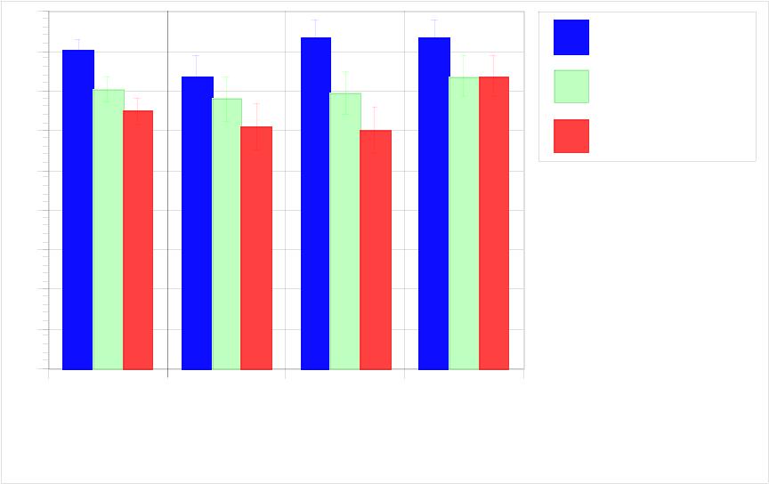
Current Situation Flight Quiz– The analysis of differences between the current and future stops
proved interesting. As shown in figures 5 and 6, we asked pilots to describe the current and next
situations in terms of altitude target, speed target, and airplane behavior. The summaries for the current
stops showed that the composite stop data (addition of altitude, speed, and behavior scores) and the
behavior data were significantly different when comparing the G-FMA group with the baseline group.
Scores for the three groups (G-FMA, training, and baseline) on the composite index were 80%, 70%,
and 65%, respectively. Looking at the number correct on just the behavior question showed the
following differences: a score of 83% for the G-FMA group, 70% for the training group, and 60%
for the baseline group. These are shown in figure 8 and in more detail in Appendix F.
23
All Categories
Speed Behavior Altitude
0
10
20
30
40
50
60
70
80
90
Guidance FMA
Training
Control
Composite
Index
Proportion of correct answers per condition for the
Current FMA Quiz (%)
Figure 8. Results on flight quiz for current situation.
Next Situation Flight Quiz– For the next situation flight quiz, we found that pilots in the G-FMA
condition performed better than pilots in the baseline group. On the composite index for the next
situation flight quiz, pilots in the G-FMA condition had a score of 83%, pilots in the training condition
scored 77%, and pilots in the baseline group scored 79%. We also found a significant difference
between the groups on the altitude question for this quiz. Pilots in the G-FMA (96%) performed better
than training condition pilots (79%) and better than the baseline pilots (64%). Looking at the pairwise
comparisons, only the difference between the G-FMA condition and the baseline condition was
significant. This indicated that groups that had the display and training were more accurate at predict-
ing what the avionics would do next than was the baseline group. These data are shown in figure 9.
Appendix F provides more detailed data on the flight quiz.
Training Ratings
A questionnaire was given to pilots to rate the characteristics of the tutor. The questions that were
selected were similar to a set of questions developed by Feary et al. (1997) to rate the same tutor in
another context. Only pilots in the display and training conditions rated the tutor, as these were the
only groups that worked with this training program. There were no significant differences found
between these two groups on any of the questions. Combined ratings of nine pilots from the display
condition and eight pilots from the training condition did not yield any remarkable results. In general,
pilots liked the training and felt that the session was worthwhile. Overall, 12 of the pilots thought the
training was good or excellent. They liked the feedback and thought it was presented in a timely
manner. Pilots also recommended that the training be used in both initial and recurrent training.
Complete training results are presented in Appendix F.
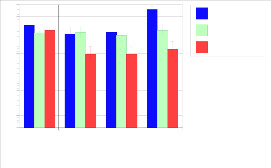
24
All Categories
Speed Behavior Altitude
0
10
20
30
40
50
60
70
80
90
100
Guidance FMA
Training
Control
Proportion of correct answers per condition for the
next FMA quiz (%)
Composite
Index
Figure 9. Results on flight quiz for future situation.
Display Ratings
We asked pilots in the display condition to rate the G-FMA in comparison with the existing FMA on
MD-11s on seven rating scales. For each question, a five-point scale was used. Results indicated an
overwhelming acceptance of the new display. Pilots felt the information was directly usable, helped
them to understand the current modes, and helped them to feel more confident about what the avionics
were doing. Most pilots reported that they would like to see the G-FMA on the MD-11.
We also asked pilots to provide comments on their experience with the G-FMA. Pilots reported that
they felt a bit uncomfortable with removing thrust and pitch from the speed FMA. One pilot
responded that the words used were not intuitive. All of the other comments were positive (see
Appendix F for a complete summary of the data).
Simulation Comments
Participants were asked to provide comments on the simulation and the fidelity of the simulation.
Most felt that it was realistic and that the flight was representative of the flight in an airplane with
regard to the displays and controls simulated. Pilots remarked that there was nothing quirky about the
displays or the simulation that they felt would influence the study.
25
DISCUSSION OF EXPERIMENTAL RESULTS
• G-FMA. The G-FMA emerged as the superior condition in this study. Looking at the objective
data, we found that the pilots in the G-FMA condition could more accurately describe the current
behavior and predict the next mode of operation than the pilots in the baseline group. Pilots in the
G-FMA group were also better at constructing the next FMA when compared with the baseline
group. The combination of training the pilot on what the vertical navigation system is doing and
then displaying that information resulted in the best demonstration of pilot knowledge of the
three groups. This may be a reflection of better understanding the avionics, more descriptive
annunciation, or both, given the types of questions that were asked.
The data obtained from the subjective questionnaire showed that pilots liked the display and
thought it was a useful device to have in the cockpit. Pilots stated that it was easier to understand
what the airplane was doing and to predict what the next FMA would look like with the G-FMA.
They also felt that the display was usable and made them more confident in their understanding of
the avionics. The G-FMA was also thought to reduce automation surprises.
Pilots in the G-FMA condition had significantly fewer hours in the airplane than did pilots in both
the training and baseline groups. This is an interesting finding because it indicates that we might
have found even better understanding if we had equated the groups on experience. As one flies the
airplane, one gains more experience with it and should understand better how it works than
someone who has not flown as much. This finding also points to the need for having a G-FMA
and advanced training available for pilots to get them up to speed and performing better with fewer
hours in the airplane than pilots without this display and training combination.
• Training. The training condition gave more correct responses (when comparing means) than the
baseline condition for all data collection metrics, but these were not significant differences at the
0.05 level. Under these conditions, we can only say that there was a trend for the training
condition to be better than the baseline condition. In the subjective evaluation, pilots reported that
they liked the tutor and that it presented the topics adequately, had an acceptable interaction, and
had an acceptable speed of training delivery. A few negative comments were received, but these
were from a minority of pilots in each case. These pilots pointed out that the displays were
cluttered, lacked enough color coding, lacked feedback, and provided a poor overall learning
experience. Again, in each of these critical areas, there were significantly fewer pilots with
complaints than those pilots who liked the tutor and found it valuable. To the overall question
that asked for a rating of the tutor, responses were largely positive and pilots found the training
program beneficial.
It is not clear how much the training adds to pilot understanding of the avionics from the current
experiment. As we mentioned before, there were trends toward the training being a positive
influence, but this was not statistically significant as calculated with post hoc pairwise comparison
tests. For each of the measures of understanding, the display group was significantly better, with
the training group having a higher, but not significantly different, mean from that of the baseline
group. This indicates that both are necessary to really make an impact on the pilot. It is not enough
26
to train pilots just in the operation of the airplane, they must also have a display that relates this
knowledge back to the task.
• G-FMA and Training. In the display condition, pilots understood the workings of the airplane at
a much higher level. We also found that this understanding applied to future understanding of
airplane states. This is an extremely powerful combination and one that can lead to improved
understanding on the part of the pilots. This understanding also can be obtained earlier
in the learning curve for the airplane.
The findings also help the pilot to better understand the three questions posed by Wiener (1989):
“What is it doing?”, “Why did it do that?”, and “What will it do next?” These three questions
were the most frequent that were heard in glass cockpits by pilots trying to figure out how the
avionics were operating. The first question relates to the present condition of the airplane, the
second to how it got into that condition, and the third to a future state of flight. Our study showed
that by training pilots and giving them the G-FMA, they were better able to answer these ques-
tions. The more knowledge that pilots have about the avionics, the less chance for an automation
surprise, and there is a greater chance for the pilots to feel that they understand what is happening
at all times and to be comfortable with the monitoring task that they are performing in automatic
flight options.
• Speed on Thrust and on Pitch. Several pilots commented that they did not feel comfortable with
our design solution to remove the speed mode that is presented on the original MD-11 FMA.
Pilots use this information to understand how their speed is being controlled at different points in
time. This is something that could be added to a future redesign of the G-FMA. We had originally
removed this information because it is contained in the behavior label, but the speed mode could
be easily added to the G-FMA with a minor realignment of the data fields
(see Appendix G, where the intentional display is discussed).
Possible Limitations
One of the limitations of the study was that the tasks for the pilots in the G-FMA condition were
easier than the other conditions and this task tracked directly to the data collection sheets. Pilots
in the G-FMA task had to tell us what the next FMA was going to look like. In this case, they only
needed to figure out the next operational procedure and put this in the window of the FMA template.
In the other two conditions, pilots had to determine both the speed and pitch modes and select the
appropriate words to describe these modes in the FMA template. The first task is inherently simpler
because there is only one mode to select and it is a much more intuitive label to the pilot because it is
more of an English-language descriptor of what the airplane will do in the next few minutes. The
operational procedure names were also used on the data collection forms, which could have made this
task easier for the G-FMA group. In the training and baseline groups, pilots had to mentally translate
what the regular FMA was telling them and convert that to an operational procedure label for the
behavior.
A second type of limitation for this study was the sample size used. We had 27 pilots in three condi-
tions, which doesn’t really provide a large amount of statistical power to reject false null hypotheses.
27
This was evident in this study because we had so many trends when comparing the training group
with the baseline group. Perhaps with more participants, this trend would have become a main effect.
FOLLOW-UP RESEARCH NEEDS
There are three areas where we feel we could improve on the current study and follow up this effort
with other research.
• We would like to extend this study to take the G-FMA and integrate this with the white, or pilot-
initiated, modes of operation. The present study asked pilots to keep the simulation in PROF, or
fully automatic operation, for as much time as possible. The hybrid modes, however, are some-
what more troublesome for pilots because they have to understand what component of the cockpit
system is controlling each of the flying functions. We need to integrate the display so that it is
more fully functional in the hybrid modes to see if there are ways to improve on these
annunciations and training.
• We could do a follow-on study in an actual simulator with visuals and flight motion to see how
the new display and training interact with the entire flight. This would add to the realism of the
study and would help to verify whether the G-FMA and training help in the full flight
environment.
• We could include additional part-task studies, such as reaction time experiments, which could be
useful in determining the advantages and disadvantages of the G-FMA in the flight environment.
CONCLUSIONS
Using the actual behavior of the avionics to design pilot training and displays is feasible and yields
better pilot performance.
When PROF is engaged, the display of the guidance mode and targets yields improved pilot
performance.
28
APPENDIX A—QUESTIONNAIRE
MD-11 Vertical Guidance Survey
Dear MD-11 Pilot:
We are conducting a research project that is examining how pilots fly the MD-11 with full automation.
We are asking all Fed Ex MD-11 pilots to help us to understand how they use PROF, how they feel
the training prepared them for the MD-11 automation, and if they have been surprised by the automa-
tion. We are looking at ways to improve training and possibly redesign your displays to make them
more “user friendly.”
As with all research using human participants, we will protect your identity and the answers that you
provide in several ways. All of the forms that are returned to us will be coded and entered into a
database without names attached. The actual forms will be shredded soon after the database is created.
Finally, all results will be reported as grouped data, no individual results will be reported.
If you have any comments or would like to relate specific instances of problems that you may have on
a regular basis, please fill out the Comments section at the end of the survey.
Please return this survey in the postage-paid envelope or mail it to:
Daniel McCrobie
Human Factors Research Group
Honeywell, Inc.
PO Box 21111 - Mail Code: 2P36D2
Phoenix AZ 85036
If you have any questions about this survey, call Daniel at (602) 436-3604 or send an e-mail with your
question to [email protected].
Thank you in advance for your helpful participation,
The VNAV Research Team,
Daniel McCrobie - Honeywell Human Factors Group
Lance Sherry - Honeywell Systems Integration Group
Jerry Kelly - Honeywell Systems Integration Group
Peter Polson - University of Colorado, Cognitive Science Department
Michael Feary - San Jose State University, Human Factors Department
Everett Palmer - NASA Ames Research Center, Human Factors Group
Please use your experience in the MD-11 to answer the following questions. For each question, fill in
the blanks or circle the option that best describes your experiences.
29
Your Background
1. When did you receive your MD-11 type rating?
3 months 6 months 1 year 2 years 3 or more years
2. Where did you do your ground school training?
MEM LGB Other: ________________________________________________________
3. Where did you do your simulator training?
MEM LGB HEL ZRH Other: ____________________________________________
4. What was your previous seat position with FedEx and in which airplane?
Captain First Officer Second Officer
B-727 A-300 DC-10 B-747 Other: ________________________________________
5. How long were you in this previous seat position?
Less than 1 year 1–2 years 2–3 years 3+ years
6. What is the majority of your previous flying background? Civilian Military
7. What other “glass cockpit” aircraft have you flown?
None or List: ___________________________________________________________
8. Your approximate total MD-11 time:
Less than 100 hours Less than 500 hours Less than 1000 hours 1000+ hours
9. Your approximate total fixed wing time:
Less than 2000 hours 2000–4000 hours 4000–7000 hours 7000+ hours
10. Your age: Less than 30 years 31–40 years 41–50 years 50–59 years
11. Your current MD-11 seat position:
Captain First Officer Flex Instructor Flight Standards Other:__________________
30
Your Use of the MD-11 Automation
1. For the climb phase of flight, I use PROF:
Always Usually Occasionally Seldom Never
2. For the approach phase of flight, I use PROF:
Always Usually Occasionally Seldom Never
3. For the descent phase of flight, I use PROF:
Always Usually Occasionally Seldom Never
4. I input winds and temperature on the Descent Forecast page:
Always Usually Occasionally Seldom Never
5. I edit the Flight Plan page to make it look like what I will fly on the approach:
Always Usually Occasionally Seldom Never
6. I use the DIR-TO page with course intercept (/XXX) when vectored to final approach:
Always Usually Occasionally Seldom Never
7. When building an approach, I erase the turn point or present position (PPOS):
Always Usually Occasionally Seldom Never
Flight Mode Annunciator (FMA) and Display Symbology
1. I use the FMA to determine what the vertical guidance is doing (i.e., PROF, PITCH, THRUST):
Always Usually Occasionally Seldom Never
2. I use the symbology on the Navigation Display (ND) to monitor where I am on the vertical path:
Always Usually Occasionally Seldom Never
3. I use the symbology on the PFD Speed Tape to determine what speed is commanded by FMS Speed:
Always Usually Occasionally Seldom Never
31
4. I use the symbology on the PFD Altitude Tape to determine what altitudes are being commanded by
PROF:
Always Usually Occasionally Seldom Never
5. I use the information on the FLT PLN page to determine the planned vertical path:
Always Usually Occasionally Seldom Never
Automation Surprises
An “Automation Surprise” occurs when the automation commands a maneuver that the pilot is not
expecting. Please tell us if you have ever experienced the following automation surprises in the
MD-11.
1. Unable to make altitude crossing restrictions in descent:
Always Usually Occasionally Seldom Never
2. Unexplained “ALT ERROR AT XXX” message:
Always Usually Occasionally Seldom Never
3. Starting down too early (i.e. before reaching Top of Descent):
Always Usually Occasionally Seldom Never
4. Abrupt pitch changes:
Always Usually Occasionally Seldom Never
5. Lack of smoothness:
Always Usually Occasionally Seldom Never
6. Unexplained “ADD DRAG” or “REMOVE DRAG” messages:
Always Usually Occasionally Seldom Never
7. Decelerations commanded too early:
Always Usually Occasionally Seldom Never
8. Decelerations commanded too late:
Always Usually Occasionally Seldom Never
32
9. Descent below charted altitude restriction in approach:
Always Usually Occasionally Seldom Never
10. Unpredictable waypoint sequencing:
Always Usually Occasionally Seldom Never
11. Unpredictable speed targets during descent:
Always Usually Occasionally Seldom Never
12. Unpredictable speed targets during approach:
Always Usually Occasionally Seldom Never
13. Unexpected level-offs:
Always Usually Occasionally Seldom Never
Training Topics
Please tell us which of the following topics you think should be covered in training. If you feel they
are adequately covered, circle “No Further Training.” If you feel that more training is needed on this
topic, tell us whether it should be done in initial or recurrent training by circling either one of those
words.
1. Additional training on how to better interpret the FMA displays:
No Further Training Initial Recurrent
2. Additional training on how to better interpret the PFD symbology:
No Further Training Initial Recurrent
3. Additional training on how to better interpret the ND symbology:
No Further Training Initial Recurrent
4. Additional training on how to interpret waypoint information on the FLT PLN page:
No Further Training Initial Recurrent
5. Using higher levels of automation (i.e., PROF, FMS SPD):
No Further Training Initial Recurrent
33
6. Understanding how PROF works during descents:
No Further Training Initial Recurrent
7. Setting up the FLT PLN page for optimum vertical navigation:
No Further Training Initial Recurrent
8. FMS Speed logic in deceleration during descent and approach:
No Further Training Initial Recurrent
9. After your initial training, how long did it take you to feel comfortable with the level of automation
that you use currently?
6 months 1 year Other_____________________________ Still not comfortable
Thank you for your help in filling out this survey.
Please feel free to add additional comments on the next page and on the back of the form.
34
Comments
Use of PROF:
FMA’s and Symbology:
Automation Surprises:
Training Topics:

35
APPENDIX B—RESPONSES FROM THE QUESTIONNAIRE
Summary Tables for the Questionnaire Data
Table B-1. Percentages of Pilots who Reported Using PROF
Phase of Flight Always Usually Occasionally Seldom/Never
Climb 73 25 2 1
Descent 20 71 7 2
Approach 5 26 27 41
Table B-2. Percentages of Pilots who Reported Modifying Aspects of the Flight Plan
Phase of
Flight/Modification
Always Usually Occasionally Seldom/Never
Erase turn-points or
positions
20 56 16 9
Use direct intercept function 11 40 27 23
Edit Flight Plan page 59 35 3 3
Input winds and
temperatures
28 28 20 24
Table B-3. Percentages of Pilots who Reported Using Displays for Surveillance
Display Used To Monitor Always Usually Occasionally Seldom
Flight Mode
Annunciation
Vertical Guidance 59 34 6 2
Navigation Display Position on Vertical
Path
37 52 10 1
Speed Tape Speed Commanded 64 34 3 0
Altitude Tape Altitude Commanded 58 36 4 3
Flight Plan Page Vertical Guidance 28 47 19 7

36
Table B-4. Percentages of Pilots who Reported Experiencing Automation Surprises
Phase of Flight/Modification Always Usually Occas. Seldom Never
Fail to make altitude
restrictions
1 5 37 47 11
Unexplained altitude errors 0 3 55 32 10
Airplane starts down too early 1 2 11 37 48
Abrupt pitch changes 0 0 7 35 57
Lack of smoothness 0 2 15 44 39
Unexpected messages 0 1 38 46 15
Deceleration too early 10 34 34 16 6
Deceleration too late 0 1 14 55 31
Descent below alt. restrictions 0 0 1 21 77
Unpredictable waypoint
sequencing
1 0 4 35 62
Unpredictable speed targets
during descent
1 9 37 39 13
Unpredictable speed targets
during approach
2 14402717
Unexpected level-offs 0 1 3 38 56
Table B-5. Percentages of Pilots who wanted Specific Training
Training Topic No Further Initial Recurrent
How to better interpret the Flight Mode Annunciator 23 51 25
How to better interpret the Primary Flight Display
symbology
43 42 16
How to better interpret the NAV Display symbology 44 39 16
How to interpret waypoint information on the FLT PLN page 47 33 20
Using higher levels of automation (e.g. PROF, FMS SPD) 27 27 46
Understanding how PROF works during descents 17 49 34
Setting up the FLT PLN page for optimum vertical
navigation
24 36 40
FMS Speed logic in deceleration during descent and
approach
84844

37
Demographic Items
These questions asked for background information about the pilot’s training, their hours on the
MD-11, and what previous planes they have flown. Additionally, we asked for the respondent’s
age to complete the demographic picture of the pilots.
1. When did you receive your MD-11 type rating?
3 months 6 months 1 year 2 years 3 or more years
Frequency 20 34 45 18 86
Percentage 10 17 22 9 43
Median = 4.0 (2 Years)
2. Where did you do your ground school training?
Memphis Long Beach Other
Frequency 134 56 13
Percentage 66 28 6
Mode = MEM
Additional Comments:
Both MEM and LGB (2)
DFW, Dallas, or AA (13)
3. Where did you do your simulator training?
Memphis Long Beach Helsinki Zurich Other
Frequency 157 27 15 3 1
Percentage 77 14 7 15 1
Mode = MEM
Additional Comments:
Both LGB and MEM
Both MEM and ZRH
Initial FO done in MEM, upgrade to Captain at London Gatewick (Formerly owned by Hughes)

38
4a. What was your previous seat position with FedEx and in which airplane?
Captain First Officer Second Officer
Frequency 68 65 66
Percentage 34 32 33
Mode = Captain Missing = 4
4b. What was your previous seat position with FedEx and in which airplane?
B-727 A-300 DC-10 B-747 Other
Frequency 95 8 56 40 4
Percentage 47 4 28 20 2
Mode = B-727
Additional Comments:
Second Officer on 727 DC-10 First Officer
DC-8 Ex Flying Tiger
First Officer on MD-11 (2) B-727 and A300
B727, before that KC-10
5. How long were you in this previous seat position?
Less than 1 year 1–2 years 2–3 years More than 3 years
Frequency 33 36 40 94
Percentage 17 18 20 46
Median = 3.0 (2–3 years)
Additional Comments:
DC-10 Captain for eight years prior to 747
6. What is the majority of your previous flying background?
Civilian Military
Frequency 101 102
Percentage 50 50
Mode = Civilian
Additional Comments:
About equal time in each (50/50) (4 responses)

39
7. What other “glass cockpit” aircraft have you flown?
None Listed another glass cockpit
Frequency 156 46
Percentage 77 23
Mode = None (No other glass cockpits flown) Missing = 1
Additional Comments:
757 (4) SF-340 (2) A300/310 (7) DC-8-72Beechjet 400A
767 (1) F-14 (3) A-300 (3) Collins EFIS G-III
EMB 120 DHC-8-300 F/A-18 (3) MD-80
A-6 Dornier 328 Gulfstream IV (3) AV-8B
F-16 (9) CE-650 F-111 F-15
8. Your approximate total MD-11 time:
<100 hr <500 hr <1000 hr >1000 hr
Frequency 16 58 37 91
Percentage 8 28 19 45
Median = 3 (Between 500 and 1000 hours)
Additional Comments:
3,000 hours (2)
140 hours
9. Your approximate total fixed wing time:
<2000 hr 2000–4000 hr 4000–7000 hr >7000 hr
Frequency 1 22 49 131
Percentage 1 11 24 65
Median = 4 (More than 7000 hours)
Additional Comments:
16,000 hours

40
10. Your age:
Less than 30 years 31–40 years 41–50 years 50–59 years
Frequency 2 50 94 57
Percentage 1 25 47 28
Median = 3 (41 to 50 years old)
11. Your current MD-11 seat position:
Captain First Officer Flex Instructor Flight Standards
Frequency 88 103 9 3
Percentage 44 50 5 2
Mode = First Officer
Additional Comments:
First Officer in upgrade to Captain (2)
Use of the MD-11 Automation
This set of questions asked the pilot to tell us how they normally flew the plane in terms of procedures
followed and use of PROF or full automatic mode. Note that FedEx procedure is for the pilot to keep
the airplane in PROF mode for as long as possible throughout the flight.
1. For the climb phase of flight, I use PROF:
Always (1) Usually (2) Occasionally (3) Seldom (4) Never (5)
Frequency 148 50 3 2 0
Percentage 73 25 2 1 0
Mean = 1.31
Additional Comments:
Acceleration at 10,000 feet is not efficient. I usually over-ride the system with vertical climb until the trend
line reach the desired airspeed, then go back to PROF again.

41
2. For the approach phase of flight, I use PROF:
Always (1) Usually (2) Occasionally (3) Seldom (4) Never (5)
Frequency 10 53 54 60 26
Percentage 5 26 27 28 13
Mean = 3.19
Additional Comments:
Except for FMS Speed Almost Always
Until Final At LAX CIVIT arrival
3. For the descent phase of flight, I use PROF:
Always (1) Usually (2) Occasionally (3) Seldom (4) Never (5)
Frequency 41 145 14 1 2
Percentage 20 71 7 1 1
Mean = 1.91
Additional Comments:
Until I am below 10,000 feet, then I use manual speed select.
Usually until I get tired or seeing poor adherence to airspeed control, then I go to V/S.
4. I input winds and temperature on the Descent Forecast page:
Always (1) Usually (2) Occasionally (3) Seldom (4) Never (5)
Frequency 56 59 41 30 17
Percentage 28 28 20 15 9
Mean = 2.48
Additional Comments:
I have captains discourage me from any wind inputs.
Did it for a while but I can’t tell the difference.
I don’t do this because the system isn’t good enough to make use of these data. Data from ATIS is not
available until the high workload phase has begun.
The old 3 miles/1000 feet and idle thrust is just as good.
If the MD-11 knows the current winds (IRS), why do I have to type in the descent winds?

42
5. I edit the Flight Plan page to make it look like what I will fly on the approach:
Always (1) Usually (2) Occasionally (3) Seldom (4) Never (5)
Frequency 119 72 7 3 2
Percentage 59 35 3 2 1
Mean = 1.52
Additional Comments:
If I know in advance.
I like to use this feature, however, it is tough to get the other guy to program the box or he will say, “ We are
too close, forget it.”
Or, I use the DIR TO and clear the turn point.
6. I use the DIR-TO page with course intercept (/XXX) when vectored to final approach:
Always (1) Usually (2) Occasionally (3) Seldom (4) Never (5)
Frequency 21 82 54 34 12
Percentage 11 40 27 17 6
Mean = 2.68
Additional Comments:
Usually, I just push APPROACH/LAND when cleared to the intercept.
If the intercept angle is greater than 30 degrees.
Almost always unless I can get the PNF to do it or if he can’t.
DIR TO and clear turn point is easier and provides the same guidance.
I always use it.
At 36C MEM, after you have built an approach going DIR TO Koley and Clian, the same Koley will get you
the same centerline extension from Koley.
7. When building an approach, I erase the turn point or present position (PPOS):
Always (1) Usually (2) Occasionally (3) Seldom (4) Never (5)
Frequency 40 113 31 14 4
Percentage 20 56 16 7 2
Mean = 2.16 Missing = 1
Additional Comments:
This messes up the distance read out on the NAV display.
Unless you mean when vectored, then always.
When being vectored in the terminal area.

43
FMA and Display Symbology
This set of questions asked pilots to rate how they use the current FMA and symbology to fly the
airplane. It also questions how they use specific symbology in relation to FMA annunciations to
determine what the system is doing at a given time.
1. I use the FMA to determine what the vertical guidance is doing (i.e., PROF, PITCH, THRUST):
Always (1) Usually (2) Occasionally (3) Seldom (4) Never (5)
Frequency 117 70 13 1 1
Percentage 59 34 6 1 1
Mean = 1.50 Missing = 1
Additional Comments:
At 10,000 feet, I go to V/S to accelerate to en route climb speed faster.
If I can remember to look after I select it.
2. I use the symbology on the Navigation Display (ND) to monitor where I am on the vertical path:
Always (1) Usually (2) Occasionally (3) Seldom (4) Never (5)
Frequency 74 107 19 2 0
Percentage 37 52 10 1 0
Mean = 1.75 Missing = 1
Additional Comments:
Taking into account what’s programmed for the approach.
Sometimes I use PERF.
With the PERF Descent page always (one or the other).
Plus a quick look at the PERF page during descent when the diamond is pegged.
ATC speed restraints dictate different air speeds.
I use the PERF page on the CDU during descent.

44
3. I use the symbology on the PFD Speed Tape to determine what speed is commanded by FMS
Speed:
Always (1) Usually (2) Occasionally (3) Seldom (4) Never (5)
Frequency 128 70 5 0 0
Percentage 64 34 3 0 0
Mean = 1.39
Additional Comments:
Boy is it screwed up!
Speeds are sometimes random.
Occasionally at 12,500 feet, I select airspeed hold 320 to keep PROF from commanding speed reduction
to 245 knots. This causes “Speed limit Exceeded” alert which goes away when PROF speed is selected
at 10,000 feet.
4. I use the symbology on the PFD Altitude Tape to determine what altitudes are being commanded
by PROF:
Always (1) Usually (2) Occasionally (3) Seldom (4) Never (5)
Frequency 116 74 8 5 0
Percentage 58 36 4 3 0
Mean = 1.51
5. I use the information on the FLT PLN page to determine the planned vertical path:
Always (1) Usually (2) Occasionally (3) Seldom (4) Never (5)
Frequency 55 95 39 12 2
Percentage 28 47 19 6 1
Mean = 2.07
Additional Comments:
PERF Page is used.

45
Automation Surprises
An “Automation Surprise” occurs when the automation commands a maneuver that the pilot is not
expecting. We asked pilots if they had ever experienced the following “automation surprises” in the
MD-11.
1. Unable to make altitude crossing restrictions in descent:
Always (1) Usually (2) Occasionally (3) Seldom (4) Never (5)
Frequency 1 9 75 95 21
Percentage 1 5 37 47 11
Mean = 3.63 Missing = 2
Additional Comments:
Note small experience level, I have only shot 25 approaches and it is difficult to be surprised too much.
Never, if programmed correctly.
Some aircraft are slow in vertical profile corrections.
Occasionally you have to keep up on it, for example with speed brakes.
2. Unexplained “ALT ERROR AT XXX” message:
Always (1) Usually (2) Occasionally (3) Seldom (4) Never (5)
Frequency 0 6 111 65 20
Percentage 0 3 55 32 10
Mean = 3.50 Missing = 1
Additional Comments:
Usually during approach phase.
3. Starting down too early (i.e., before reaching Top of Descent):
Always (1) Usually (2) Occasionally (3) Seldom (4) Never (5)
Frequency 2 5 22 75 96
Percentage 1 2 11 37 48
Mean = 4.30 Missing = 3
Additional Comments:
Although Top of Descent was too early.
No need to start down so early.
Slowdowns are usually our normal operations, I almost always do a level change instead of PROF in descent.

46
4. Abrupt pitch changes:
Always (1) Usually (2) Occasionally (3) Seldom (4) Never (5)
Frequency 0 0 15 69 116
Percentage 0 0 7 35 57
Mean = 4.51 Missing = 3
Additional Comments:
Usually on the ground at touchdown, never in the air.
Some aircraft have very rough pitch controllers.
5. Lack of smoothness:
Always (1) Usually (2) Occasionally (3) Seldom (4) Never (5)
Frequency 0 4 30 88 80
Percentage 0 2 15 44 39
Mean = 4.22 Missing = 1
Additional Comments:
Slow to correct for incorrect descent rates.
Especially on non protected ILS approaches with wavering raw data. It’s like being in a rowboat with
three foot swells.
It is almost too smooth and deliberate.
6. Unexplained “ADD DRAG” or “REMOVE DRAG” messages:
Always (1) Usually (2) Occasionally (3) Seldom (4) Never (5)
Frequency 0 2 76 92 31
Percentage 0 1 38 46 15
Mean = 3.76 Missing = 2
Additional Comments:
Sometimes as a result of using DIR INTC.

47
7. Decelerations commanded too early:
Always (1) Usually (2) Occasionally (3) Seldom (4) Never (5)
Frequency 20 70 70 31 12
Percentage 10 34 34 16 6
Mean = 2.74
Additional Comments:
Always when out approximately 13,000 feet and slowing down to 245 knots.
On Approach/Final.
The -910 software FOOT + 5 at 13–14,000 feet in descent.
From 11,000 to 10,000 feet with no speed restrictions. I have yet been able to edit the speed in PROF to
maintain 350/320 without going manual.
Especially with -910 during approach. FOOT + 5 is too slow.
I normally see the hollow speed ball drop down while on vectors to final at a speed of my choice or by ATC,
so I can’t answer questions 7 or 8.
Descending through 12,500 feet en route to 10,000 feet.
This is due to a JAL or KAL mole in your software department. They always slow to 245 @ 50 to 60 miles out.
8. Decelerations commanded too late:
Always (1) Usually (2) Occasionally (3) Seldom (4) Never (5)
Frequency 0 2 27 110 63
Percentage 0 1 14 55 31
Mean = 4.15 Missing = 1
Additional Comments:
Seldom associated with descent.
9. Descent below charted altitude restriction in approach:
Always (1) Usually (2) Occasionally (3) Seldom (4) Never (5)
Frequency 0 0 2 43 156
Percentage 0 0 1 21 77
Mean = 4.78 Missing = 2
Additional Comments:
Never, if entered correctly in the flight plan page.

48
10. Unpredictable waypoint sequencing:
Always (1) Usually (2) Occasionally (3) Seldom (4) Never (5)
Frequency 1 0 7 69 125
Percentage 1 0 4 35 62
Mean = 4.56 Missing = 1
Additional Comments:
Deletion of ABEAM points when DIR TO with ABEAMS was commanded.
Never the aircraft’s fault. I’ve managed to mess it up myself.
Seldom with the -911 load.
11. Unpredictable speed targets during descent:
Always (1) Usually (2) Occasionally (3) Seldom (4) Never (5)
Frequency 3 18 75 80 26
Percentage 1 9 37 39 13
Mean = 3.56 Missing = 1
Additional Comments:
From the teens to 10,000 foot level-off than in the App Program.
12. Unpredictable speed targets during approach:
Always (1) Usually (2) Occasionally (3) Seldom (4) Never (5)
Frequency 4 28 81 55 34
Percentage 2 14 40 27 17
Mean = 3.45 Missing = 1
Additional Comments:
The aircraft goes too fast or wants to go too fast in descent. It goes up into the high speed red speed bar. I see
this often an it is my biggest objection to descent in PROF.
Occasionally- Generally when you have 28 Flaps and FMS speed, the V Ball and speeds are sometimes weird.
That’s because we are macho, want to do speed selection, and we don’t watch or use the FMS until it is dirty.
Occasionally after the FMS speed selection on Final with gear down and flaps at 35/50, I get a solid magenta
ball that jumps to a higher speed between 185 and 205.
I have seen the FMS speed ball bounce between 245 knots and FMS speed.
Before Flaps 35 or 50.
Wrong, but predictable.
Recently, I saw FOOT + 25 knots with the flaps set at 35.

49
13. Unexpected level-offs:
Always (1) Usually (2) Occasionally (3) Seldom (4) Never (5)
Frequency 0 1 12 76 113
Percentage 0 1 3 38 56
Mean = 4.48 Missing = 1
Additional Comments:
Usually this results from using DIR and NTC.
Training Topics
This last section asked pilots to determine whether a given topic should be covered in the training or
learned on the line. If the topic was adequately covered, they responded with “No Further Training.”
If they felt that more training was needed on this topic, they told us whether it should be done in initial
or recurrent training.
1. Additional training on how to better interpret the FMA displays:
No Further Initial Recurrent
Frequency 47 102 51
Percentage 23 51 25
Mode = Initial Missing = 3
Additional Comments:
Change the whole training to more classroom and less CMI.
Buy new MD-11 pilots both Honeywell manuals.
Screwy question. If it needs to be done in initial, it needs to be reinforced in recurrent, these are not mutually
exclusive.
Especially speed on thrust versus speed on pitch.
Good review.
Do a better job.
Initial definitely. Recurrent good to do also.
Slow the simulator down at each phase of flight and point out what the FMA is telling us. I think this would
enhance the FMA interpretation.

50
2. Additional training on how to better interpret the PFD symbology:
No Further Initial Recurrent
Frequency 85 81 32
Percentage 43 42 16
Mode = No Further Training Missing = 5
Additional Comments:
We need flight safety feedback on instances that occur on the line. Discuss line operations that have occurred.
3. Additional training on how to better interpret the ND symbology:
No Further Initial Recurrent
Frequency 87 78 33
Percentage 44 39 16
Mode = No Further Training Missing = 5
Additional Comments:
The symbols displayed on the MCDU, especially those that come up in the terminal arrival phase, are not
explained in the flight manual.
4. Additional training on how to interpret waypoint information on the FLT PLN page:
No Further Initial Recurrent
Frequency 93 64 41
Percentage 47 33 20
Mode = No Further Training Missing = 5
5. Using higher levels of automation (i.e., PROF, FMS SPD):
No Further Initial Recurrent
Frequency 52 53 94
Percentage 27 27 46
Mode = Recurrent Missing = 5
Additional Comments:
When weather is windy in ANC or HKG, the automation is worthless. You need more physical transitions to
severe runway wind and turbulence conditions.
It is critical at initial. The levels of automation and how to mix and match them must be emphasized and
reviewed more.

51
6. Understanding how PROF works during descents:
No Further Initial Recurrent
Frequency 35 97 67
Percentage 17 49 34
Mode = Initial Missing = 4
Additional Comments:
Sometimes it has a mind of its own. Usually it is not a fuel-efficient descent.
At initial it wouldn’t hurt.
And the engine out profile at altitude.
How does it work during descent? I can’t find any consistent logic behind it.
Or doesn’t work.
7. Setting up the FLT PLN page for optimum vertical navigation:
No Further Initial Recurrent
Frequency 47 73 78
Percentage 24 36 40
Mode = Recurrent Missing = 5
Additional Comments:
At initial it wouldn’t hurt.
Irrelevant unless I can understand what PROF is trying to do.
IOE (2)
8. FMS Speed logic in deceleration during descent and approach:
No Further Initial Recurrent
Frequency 15 96 88
Percentage 8 48 44
Mode = Initial Missing = 3
Additional Comments:
Is there logic there?
More advanced knowledge on this logic would be helpful.
What speed logic?
Don’t use it.
IOE
At initial it wouldn’t hurt.
New FMC -911 load
This lacks consistency in performance. I don’t understand the speed logic on descent.

52
9. After your initial training, how long did it take you to feel comfortable with the level of automation
that you use currently?
6 months 1 year Other Still not comfortable
Frequency 70 59 37 32
Percentage 35 30 19 16
Mode = 6 months Missing = 5
Additional Comments:
I wouldn’t use FMS speed or autothrottles if I wasn’t required to do so.
I am still not comfortable with PROF descents. Both PROF and Speed are inconsistent from one flight to
another.
These seem to be arbitrary.
But I learn something new on a continuous basis.
Comfortable but I do not trust it, particularly after a new load is installed.
I am comfortable with the aircraft and automation but I am still feeling like I am learning and improving every
flight. The most uncomfortable phase is the last 200 feet in landing because I know the aircraft can bite
me quickly and I don’t get much practice at this phase.
Soon because of my Airbus FMS/Honeywell background.
I am still not comfortable. I felt better in IOE than now due to a lack of proficiency.
I am not comfortable trusting the system. This may be good because I don’t become complacent.
I am still not comfortable and working on displays.
I am still very wary of this system, it seems as though there are booby traps out to get you when you let your
guard down.
About 1 year, we don’t fly much in the beginning.
After about 400 hours of flight.
I am too new to comment.
Not there yet at 50 hours and 6 landings.
Immediately.
One month (5).
One to two months (2).
Two months (4).
Two to three months (2).
Three months (4).
Four months.
Four to five months.
Less than six months (2).
Six months to a year.
Eight months and still learning.
Ten months.
Two years (2).
Summary of Open-Ended Comments
Additionally, pilots were asked to provide comments on four topics: use of automated vertical
navigation, interpretation of the FMA, automation surprises, and training. For each category, between
45 and 80 pilots filled in comments on this last page of the questionnaire. The comments have been
summarized under topic categories with the number of comments in this category following the short
name of the topic.
53
Use of PROF– There were the most comments provided in this topic area with 80 pilots providing
one or several comments in this area. The responses were consolidated into the categories, although
there were many more single comments that did not fall into a category. This method summarizes the
thrust of the comments provided and attempts to capture the overall feeling of comments that were
made in this category.
ATC (6) - The ATC system limits the use of PROF in descent. They vector the plane to a
course and this requires pilots to come out of PROF and into a more hybrid automation.
Descent (21) - PROF is difficult to use when the plane was in descent less than 10,000 feet.
Pilots also felt that the plane slows down too early in this mode.
Design (5) - These comments dealt with specific features that pilots liked or disliked about the
logic and control design.
Good (16) - Pilots liked using PROF and thought that it was a great system.
Speed (7) - The speed control on the plane is confusing. Other comments in this section
pointed to PROF being too conservative and this causes pilots to come out of PROF too early.
Training (6) - We are not adequately trained in PROF operation.
Trust (4) - Don’t use PROF because it has let me down before and I do not trust it.
Usage (13) - Pilots reported that they felt that they needed experience to use PROF and feel
comfortable with it. One pilot stated that you need at least 60 landings in the system to achieve
proficiency. They also felt that there were many ways to improperly set up the system (pilot
entered data) so that problems were created later in the flight.
Workload (2) - PROF can increase pilot workload in scanning because there are more data
points to look at.
FMA and Symbology– There were 45 pilots responding in this category. The breakdown of
comments is as follows:
Design (13) - Comments in this category requested additional symbology, changes to
symbology and changes in the color scheme for information.
Good (10) - These pilots reported that they liked the current FMA and had no problems with it
or symbology in general.
Training (11) - Pilots wanted an FMA trainer and more training in interpretation of the
displays.
Understanding (2) - These comments focused on the length of time that it takes a pilot to
learn the system symbols. One pilot suggested this was a six-month process.
54
Usage (9) - Comments in this category include the observation that you have to look else-
where besides the FMA to get the whole story of what is going on. Others thought that the
FMA was too confusing.
Automation Surprises– 56 pilots provided comments on automation surprises. These responses
were coded into categories based on the primary thrust of the pilot’s response. Five categories were
created with ten of the responses not fitting into one of the five categories. The categories, numbers of
responses in each category, and a brief summary of the comments are provided below:
Approach (2) - Surprises always happen below 10,000 feet.
Design (9) - As the FMS product matures, there are fewer surprises. Pilots are unaware of the
underlying “obscure logic” being used in the FMS. It was reported to be frustrating to enter
waypoints and get error messages because they are too close to the airplane. Inserting
approaches is not the same for different parts of the world. We are not given FMS
conventions. Can drop out of PROF or NAV mode without a warning.
Experience (15) - Surprises come from not understanding the system. Many errors are pilot
induced and these decrease with experience. When pilots don’t know how the system works, it
is easy to be surprised.
Speed (18) - The plane slows too early. FMS Speed mode causes surprises. This plane places
a priority on airspeed over altitude, which is a problem when you have speed- and altitude-
constrained waypoints.
Trust (2) - Not confident that it will make altitude restrictions. I never trust the automation
completely.
Training– 45 comments on training were collected in the following categories:
Additional (2) - Need more training on the FMS.
Aids (3) - Need learning aids to help teach and learn the system. Learning and refresher aids
would be nice. A standard method for initial training was also suggested.
Basics (15) - Stick to a basic approach to training, teach the “must know” parts first, “should
know parts second, and then go into “nice to know” aspects.
Design (2) - Use the Airbus design to simplify the system.
FMS Trainer (20) - Need an FMS trainer so that system pilots can use this on their own and
get more hands-on training on the FMS.
Poor (3) - The training is poor and needs to be improved.

55
APPENDIX C—EXAMPLE OF THE TUTOR USED IN THE EXPERIMENT

56

57

58

59
60
APPENDIX D—EXPERIMENTAL PROCEDURE AND SIMULATED FLIGHT
The following values were entered via the MCDU into the FMS:
In the INIT Page
KPDX/KSEA (KPDX is approx. N45.6, W122.62, Runway 10R)
Cost Index of 200 (FedEx) or 80 (Swiss Air)
Flight Number 0014
Final Cruise Altitude of FL330
Gross weight of 400,000 pounds
Fuel at 38,000 pounds per tank, tip tanks-full
TOCG (Take-Off Center of Gravity) 30.0
ZFWCG (Zero Fuel Weight Center of Gravity) 24.0
Flex of 50
In the Flight Plan Page
KPDX SID (standard instrument departure) of 10R
Add IMB (Kimberly) waypoint to the flight plan
Add CHINS2 arrival as a STAR (Standard Arrival)
Add AUBURN FMS Transition as a STAR
Add 16R as runway for Seattle
In the Takeoff/Approach Page
Air Temperature set to 15 degrees C
Winds set to 0 miles per hour / 0 degrees direction
Confirm the V-Speeds

61
Situation ATC Instruction PNF Tasks
At Runway
threshold
FDX 14 cleared to KSEA via Kimberly. Maintain
5000 feet, expect FL330 10 minutes after departure.
Maintain 250 knots until further advised.
Set up FMS, perform after
start and below the line
checklists, set the flaps, set
the stabilizer and trim
At runway
threshold
FDX 14 cleared for Takeoff, runway heading
After check-in FDX 14, radar contact, climb and maintain 12,000 Retract flaps and slats
At 5000 ft FDX 14 turn left direct KIMBERLY when able Perform Direct To function
At 9500 ft FDX 14 climb and maintain FL 190
Above
10,000 ft
Observe if 250 knot speed
restriction was followed
At 10,500 ft FDX 14 resume normal speed
At 12,000 ft Stop 1 (Climb) Collect Question and FMA
data
At 12,500 ft FDX 14 cleared direct CHINS when able
At 19,000 ft Stop 2 (Climb Intermediate Level) Collect Question and FMA
data
At 19,500 ft Climb and maintain FL310, this will be your final
altitude
At 26,000 ft Stop 3 (Climb) Collect Question and FMA
data
At 31,000 ft Stop 4 (Cruise) Collect Question and FMA
data
At 31,000 ft Stop 5 (Cruise) Collect Question and FMA
data
At 31,000 ft
about 35 mi
short of CHINS
FDX 14, descend and maintain FL 260 (note: if pilot
asks if this is discretionary, say that it is not)
At 29,000 ft Stop 6 (Early Descent) Collect Question and FMA
data
At 26,000 ft
and after
passing path
Stop 7 (Late Descent) Collect Question and FMA
data
After Stop FDX 14, descend and maintain FL 110
Approx
16,000 ft
prior to
intercepting
the path
Stop 8 (Descent) Collect Question and FMA
data
62
APPENDIX E—ANALYSIS OF VARIANCE (ANOVA) FOR EACH QUESTION ASKED
DURING THE EXPERIMENT
FMA Template Data
These data were collected at each of the eight stops. The data were scored as 1 for a correct score or 0
for an incorrect score. The mean values were calculated for each of the stops. A value of 1 in the table
indicates that all participants got the question correct and there were no errors. A value of 0 in the table
indicates that all participants got the question incorrect. The means of each condition are presented
below for each of the three conditions.
One way ANOVAs were run on the questions that were recorded. Significance values are reported as
either non-significant (ns) or with the associated p-value. Significant differences are reported in Bold
font to distinguish them from non-significant differences. All conditions had nine participants and
there were no missing values.
The Whiz Wheel values for the G-FMA condition are repeated so they can be compared against the
speed and altitude modes. If you will recall, the G-FMA had just a single mode response category
where the participant built the G-FMA using the next operational procedure. The values are repeated
so that accurate comparisons can be made between the three conditions.
Stop 1 Speed Spd Mode Pitch Mode Altitude
G-FMA 1.0 .67 .67 1.0
Training 1.0 .89 1.0 1.0
Baseline 1.0 1.0 .89 1.0
significance ns ns ns ns
Stop 2 Speed Spd Mode Pitch Mode Altitude
G-FMA 1.0 .89 .89 1.0
Training 1.0 .67 .78 1.0
Baseline .89 .56 .67 1.0
significance ns ns ns ns
63
Stop 3 Speed Spd Mode Pitch Mode Altitude
G-FMA 1.0 1.0 1.0 1.0
Training 1.0 1.0 1.0 1.0
Baseline 1.0 .89 .78 1.0
significance ns ns ns ns
Stop 4 Speed Spd Mode Pitch Mode Altitude
G-FMA 1.0 .89 .89 1.0
Training 1.0 .67 .68 .68
Baseline 1.0 .11 .56 .89
significance ns .001 ns ns
Stop 5 Speed Spd Mode Pitch Mode Altitude
G-FMA 1.0 1.0 1.0 1.0
Training 1.0 .89 .78 .78
Baseline .89 .78 .78 .89
significance ns ns ns ns
Stop 6 Speed Spd Mode Pitch Mode Altitude
G-FMA 1.0 .89 .89 1.0
Training 1.0 .89 1.0 1.0
Baseline .89 1.0 .89 .78
significance ns ns ns ns
64
Stop 7 Speed Spd Mode Pitch Mode Altitude
G-FMA 1.0 .78 .78 1.0
Training .89 .78 .89 .89
Baseline .78 .67 .78 1.0
significance ns ns ns ns
Stop 8 Speed Spd Mode Pitch Mode Altitude
G-FMA .67 .56 .56 1.0
Training .78 .33 .44 1.0
Baseline .56 .33 .11 1.0
significance ns ns ns ns
Results for Flight Quizzes
At each stop in the scenario (except for Stop 5), pilots were requested to fill out a set of three questions
asking what was the speed target, what was the altitude target, and what was the behavior of the
airplane. The first set of three questions was to apply to the current situation of the avionics (desig-
nated with an “a” below), and the second set was to apply to what the avionics would do next
(designated with a “b” below). Questions were the same for all three conditions.
Each question was coded as a correct answer (value of 1.0) or incorrect (value of 0.0). A value of 1.0
in the table below indicates that all pilots in that condition got that question correct and there were no
errors. The same reporting scheme is used as was done for the Whiz Wheel data above.
65
Stop 1a (Current) Speed Behavior Altitude
G-FMA .89 .89 1.0
Training .78 .67 1.0
Baseline .78 .67 1.0
significance ns ns ns
Stop 1b (Next) Speed Behavior Altitude
G-FMA .22 .78 1.0
Training .33 .89 .89
Baseline .44 .56 .67
significance ns ns ns
Stop 2a (Current) Speed Behavior Altitude
G-FMA .89 1.0 .89
Training .56 1.0 .89
Baseline .56 .56 .89
significance ns .01 ns
Stop 2b (Next) Speed Behavior Altitude
G-FMA .89 .63 1.0
Training 1.0 .56 .89
Baseline .68 .33 .67
significance ns ns ns
66
Stop 3a (Current) Speed Behavior Altitude
G-FMA 1.0 1.0 1.0
Training 1.0 .56 .78
Baseline 1.0 .67 .78
significance ns ns ns
Stop 3b (Next) Speed Behavior Altitude
G-FMA 1.0 1.0 1.0
Training 1.0 1.0 .89
Baseline .89 1.0 1.0
significance ns ns ns
Stop 4a (Current) Speed Behavior Altitude
G-FMA 1.0 1.0 1.0
Training .89 1.0 1.0
Baseline .89 1.0 1.0
significance ns ns ns
Stop 4b (Next) Speed Behavior Altitude
G-FMA 1.0 .78 .89
Training 1.0 .89 .89
Baseline 1.0 .89 .44
significance ns ns .04
67
Stop 5b (Next) Speed Behavior Altitude
G-FMA 1.0 1.0 1.0
Training .89 .78 .89
Baseline .78 .78 .56
significance ns ns .04
Stop 6a (Current) Speed Behavior Altitude
G-FMA .89 1.0 1.0
Training 1.0 1.0 1.0
Baseline .78 .67 .67
significance ns .03 ns
Stop 6b (Next) Speed Behavior Altitude
G-FMA .63 .89 .89
Training .44 1.0 .89
Baseline .11 .56 .89
significance .05 .03 ns
Stop 7a (Current) Speed Behavior Altitude
G-FMA .78 .89 .89
Training .44 .44 .67
Baseline .68 .56 .67
significance ns ns ns
68
Stop 7b (Next) Speed Behavior Altitude
G-FMA .67 .78 .89
Training .67 .78 .44
Baseline .11 .56 .56
significance .02 ns ns
Stop 8a (Current) Speed Behavior Altitude
G-FMA .44 .89 1.0
Training .78 .89 .56
Baseline .22 .67 .89
significance ns ns .04
Stop 8b (Next) Speed Behavior Altitude
G-FMA .67 .44 1.0
Training .89 .11 .56
Baseline .78 .11 .33
significance ns ns .01

69
APPENDIX F—RESULTS FROM THE SIMULATION EXPERIMENT
Training Ratings
A questionnaire was given to pilots to get them to rate the characteristics of the tutor. Only pilots in
the display and training conditions rated the tutor as these were the only groups that worked with this
training program. There were no significant differences found between these two groups on each
question. The data presented are the combined ratings of nine pilots from the display condition that
saw the training and eight pilots from the training condition. In this second case, one of the pilots did
not fill out a rating form for the tutor and this was not discovered until after the pilot had left the
building and returned home. Numbers are presented in a frequency distribution for that question. For
example, in the question on speed of presentation, two pilots felt that the presentation was too slow,
while fifteen felt that the speed was about right.
Speed of presentation Too slow Slow
2
About right
15
Fast Too fast
Interaction with tutor Too little interaction About right
17
Too much interaction
Interaction style Good interaction style Neutral
10
Poor interaction style
7
Depth of subject
matter
Too much depth Enough detail
12
Not enough depth
5
Presentation of topics Great presentation
6
Adequate presentation
11
Poor presentation
Difficulty of questions Too easy
1
Easy
5
About right
11
Hard Too hard
Graphics Needs improvement
4
About right
5
Good
8
Information density Too much white space About right
16
Too cluttered
1
Use of color Too little color
1
About right
16
Too much color
Feedback Adequate feedback
13
Neutral
1
Too little feedback
3
Speed of feedback Timely feedback
11
Neutral
6
Feedback too slow
Training effective in
initial
No Somewhat effective
4
Effective
6
Very effective
7
Training effective in
recurrent
No Somewhat effective
2
Effective
8
Very effective
7
How much did you
learn about VNAV
Very little
2
A bit Some
13
A great deal
2
How would you rate
the tutor overall
Terrible Poor
1
OK
4
Good
10
Excellent
2
70
Display Ratings
We asked pilots to rate the G-FMA in comparison to the existing FMA on MD-11s on seven rating
scales. For each question, a five-point scale was used and was coded as follows:
Strongly Agree 1
Agree 2
Neutral 3
Disagree 4
Strongly Disagree 5
The following were the questions that were given to the display group. For each question, the results
are presented as the mean and standard deviation of each question using the rating scale above.
Mean (Std Dev)
The G-FMA display provided me with information that was directly
usable.
1.67 (0.71)
The G-FMA display was helpful in my understanding of what the plane
was doing.
1.67 (0.71)
The G-FMA display helped me to understand the current mode of the
airplane.
1.56 (0.53)
I felt more confident in my understanding of the avionics with the
G-FMA display.
2.11 (0.78)
I feel that the G-FMA display would help to minimize automation
surprises.
1.89 (1.05)
I used the Operational Procedure name to help me to understand what
the avionics were doing.
2.22 (0.73)
I would like to see the new display on all Fed Ex MD-11s. 1.56 (0.73)
We also asked pilots to provide comments they had about the G-FMA. This was an open-ended
question at the bottom of the questionnaire. The following comments were obtained from this inquiry.
Each paragraph represents the complete comment that a pilot made about the new display.
Liked new FMA, but I am uncomfortable with removing thrust and pitch from the speed
FMA. Speed on pitch can cause tailstrikes and this understanding is critical. Uncertain as to
whether the new FMA will help or hinder this understanding.
G-FMA will be a useful tool/constant reminder of the AC position in relation to the FMS
generated Vertical Flight Path. Along with the vertical path indicator, the words Early DES,
Late DES are helpful indicator to this end. Display is good for Vertical Situation Awareness.
71
Felt more confident in knowing what phase of flight the plane was in, not necessarily an
understanding of the avionics. Incorporating some more speed information would be useful.
Need speed on pitch/thrust combined with what phase of flight you are in.
Words used are not intuitive. Missed not having Pitch or Thrust available in speed FMA.
Additional mode complexity may not enhance pilots ability to understand current mode.
Possibly different colors could be used for the unusual or different modes of vertical
navigation, such as an alt constraint without having to look at the MCDU to verify.
Simulation Comments
Participants were asked in open-ended questions to rate the simulation and how well they thought the
simulation approached normal flight. When asked how closely the simulation duplicated the reality of
flying FedEx MD-11s, most of the pilots (21 of 27, or 78%) stated that the simulation was close. Two
of the pilots indicated that we should do the study in a full-motion simulator, with one of those pilots
stating that we should get a full FedEx crew for the flight and fly a more complete scenario. Two other
pilots rated the simulation as “Fair,” and one pilot stated that it was not a very close simulation and
more emphasis on flight procedures was needed.
We also asked the pilots if there were any quirks in the displays or the way the simulator flew
compared with the real airplane. Seventeen pilots stated that they did not see any differences (62%).
Three pilots commented on failures that were shown on the equipment acquisition document (EAD).
This was due to our simulation and the fact that we were only running one FMC during the simula-
tion. Three others commented on the differences in the FMAs; these pilots were in the display
condition and were expected to see different FMA displays. We also had had two reports of
simulation glitches, which may have been unique to the simulator.
A third question asked pilots if there was anything about the simulation that would influence the
results of the study. Sixteen (59%) of the participants said there wasn’t anything that they felt would
influence the study. Other comments that we received in this section were: need more climbs and
descents, a two-man crew should be used, background talking was a distraction, and I should have
been more prepared. These comments were individual comments that did not seem to fit the specific
question that was asked.
Next FMA Error Data
At each stop, we asked pilots to build the next FMA that they would see (see figs. 7 and 8 for a
pictorial of the FMA template that were used to collect these data). This was done to continually verify
the pilot’s understanding of what was coming up next. As pilots understand the avionics, they should
be better able to tell us what the avionics will look like in the future. For the All column, all of the
responses at each of the stops were added together for each participant. There was a significant differ-
ence with the G-FMA condition being significantly higher than the baseline group. This indicates that
the G-FMA group got more of these responses correct than did respondents in the baseline group,

72
hence they had a better understanding of the avionics. Examining the components that went into this
overall score, however, did not identify any significant differences.
Group All Stops Speed Spd Mode Pitch Mode Altitude
Guid. FMA 29.00 7.7 6.7 6.7 8.00
Training 27.67 7.7 6.1 6.6 7.33
Baseline 25.33 7.0 5.3 5.4 7.56
significance .03 ns ns ns ns
Error data were also collected when pilots responded to the flight quiz. These data showed that there
were significant differences between the groups for the composite index and for the behavior and
altitude indices. There was a significant difference between the baseline and G-FMA groups for the
All stops index, but neither the behavior nor the altitude indices had pairwise comparisons that were
significant at the 0.05 level. These data support the notion that the understanding of the vertical
guidance procedures was enhanced with the G-FMA and with the training groups. Both of these
groups had higher scores which indicate that they got more correct in these categories.
Group All Stops Speed Behavior Altitude
Guid. FMA 39.22 12.00 12.78 14.44
Training 35.44 11.67 11.57 12.22
Baseline 30.22 9.67 9.56 11.00
significance .01 ns .01 .01
Looking at the differences between the Current and Next stops proved interesting. The Current stops
were those where we asked pilots to describe the current situation in terms of altitude target, speed
target and airplane behavior. The Next stops asked pilots to describe those same concepts but off in the
future. Looking at the summaries for the Current and Next stops, we found that the overall stop data
were significant at both times. For the Current stops, the behavior that was mentioned was signifi-
cantly different, with the G-FMA group being significantly different from the baseline group. Overall,
the Current stops were different between the G-FMA and baseline groups as well.

73
For the Next stop data, we found that, overall, the G-FMA condition was significantly different from
both the baseline and training groups. The table below shows that, overall, there was a significant
difference between the groups for all Current stops and all Next stops, indicating that understanding
was greater for groups that had the display and training when compared to the baseline group. For the
Current stops, it appears as if the behavior component was the significant contributor while the
significant contributor for the Next stops was the altitude component. This indicates that the G-FMA
group was better than the other two groups in stating what the behavior of the airplane was for the
current situation, and they were better at pointing out the source of the altitude targets for the next
situation.
Current Stops Next Stops
Group All Speed Beh. Alt. All Speed Beh. Alt.
Guid. FMA 19.22 5.89 6.67 6.67 20.00 6.11 6.22 7.67
Training 16.89 5.44 5.56 5.89 18.56 6.22 6.00 6.33
Baseline 15.56 4.89 4.78 5.89 14.67 4.78 4.78 5.11
significance .01 ns .01 ns .01 ns ns .01

74
APPENDIX G—DESCRIPTION OF THE INTENTIONAL FMA
The annunciation for the automation of the vertical flight path management function should
communicate the items listed in table G-1. The operational procedures, scenarios, behavior outputs,
and behavior output functions may be annunciated on the FMA as illustrated in figure G-1. The
scenario inputs can be annunciated on a vertical situation display (VSD).
Table G-1. Contents of Annunciation for Automated Vertical Flight Path Management
Content OPM Element Automation for Vertical Flight Path
Management
Intention Operational Procedure Name VG Operational Procedure Name
Reason for Intention Scenario Name Scenario Name
Behavior Behavior Outputs and their
Functions
Altitude Target - Function
Speed Target - Function
Vertical Speed Target - Function
Pitch/Thrust Control Mode - Function
Next Speed Target Next Vertical Guidance
Operational Procedure
Next Altitude Target
Next Speed Target Behavior
Output Function
Next Pitch/Thrust Control Mode Next Altitude Target Behavior
Output Function
Speed Target Vertical Guidance
Operational Procedure
Altitude Target
Speed Target Behavior
Output Function
Pitch/Thrust Control
Mode
Altitude Target Behavior
Output Function
(a) Layout for Intentional-FMA
260 PATH DESCENT 3000
Econ Descent CAS PATH | IDLE-THRUST Constraint at Approach Fix
280 LATE DESCENT 15000
Econ Descent CAS + 20
knots
SPEED | IDLE-THRUST Clearance Altitude
(b) Example Intentional-FMA
Figure G-1. Example FMA for automated vertical flight path management.
75
REFERENCES
Babbitt, B. A.; and Nystrom, C. O.: Training and Human Factors Research on Military Systems:
Questionnaire Construction Manual. Fort Hood, TX: Army Research Institute for the
Behavioral and Social Sciences (Tech Reports 89-20 and 89-21), 1989.
Billings, C. E.: Aviation Automation: The Search for a Human-Centered Approach. Mahwhad, NJ:
Lawrence Erlbaum, 1997.
Crowther, E. G.; Chappell, A. R.; and Mitchell, C. M.: VNAV Tutor: System Knowledge Training
for Improving Pilot’s Mode Awareness. Paper presented at the 1994 IEEE International
Conference on Systems, Man, and Cybernetics, San Antonio TX, Oct. 1994.
Eldredge, D.; Mangold, S.; and Dodd, R. S.: A Review and Discussion of Flight Management
System Incidents Reported to the Aviation Safety Reporting System (Final report no.
DOT/FAA/RD-92/2). Washington, DC: Battelle/U.S. Department of Transportation, 1992.
Endsley, M. R.: Measurement of Situation Awareness in Dynamic Systems. Human Factors, vol. 37,
no. 1 , 1995, pp. 65–84.
Feary, M.: Control-Based vs. Guidance-Based Training and Displays for Automated Vertical
Guidance. Unpublished master’s thesis, San Jose, CA.: San Jose State University, 1997.
Feary, M.; Alkin, M.; Palmer, P.; Sherry, L.; McCrobie, D.; and Polson, P.: Behavior-Based vs.
System-Based Training and Displays for Automated Vertical Guidance. In Proceedings of the
Ninth International Symposium on Aviation Psychology, Columbus, OH, 1997.
Funk, K.; Lyall, B.; and Riley, V.: A Comprehensive Analysis of Flightdecks with Varying Levels of
Automation (Phase 1 Final Report—Perceived Human Factors Problems of Flightdeck
Automation). Eugene, OR: Oregon State University, 1995.
Hutchins, E.: Integrated Mode Management Interface Final Report. NASA Ames Research Center,
1996.
Hutchins, E.: Mode Management Made Simple. La Jolla, CA: University of California, San Diego,
1992.
Hutchins, E. L.; Hollan, J. D.; and Norman, D. A.: Direct Manipulation Interfaces. In D. A. Norman
and S. W. Draper, eds., User Centered System Design. Hillsdale, N. J.: Erlbaum, 1986.
Mangold, S. J.; and Eldredge, D.: Flight Management Systems Information Requirements.
In R. S. Jensen, ed., Proceedings of the Eighth International Aviation Psychology Symposium
Conference, Columbus: Ohio State University Press, 1995.
76
McRuer, D.; Ashkenas, I.; and Graham, D.: Aircraft Dynamics and Control. Princeton, NJ: Princeton
University Press, 1973.
Palmer, E.: “Oops, It Didn’t Arm.” A Case Study of Two Automation Surprises. Paper presented at
the 1995 Aviation Psychology Meeting, 1995.
Palmer, E.; Hutchins, E.; Ritter, R.; and vanCleemput, I.: Altitude Deviations: Breakdowns of an
Error Tolerant System. NASA TM-108788, 1993.
Sarter, N.; and Woods, D.: Pilot Interaction with Cockpit Automation: Operational Experiences of
the Flight Management System. International J. Aviation Psychology, vol. 2, no. 4, 1992,
pp. 303–321.
Sherry, L.; Kelley, J.; McCrobie, D.; Polson, P. G.; Feary, M.; Hynes, C.S.; and Palmer, E.: Design
of an Intentional Vertical Flight Path Management Function for the HSCT Cooperative
Cockpit. Honeywell publication no. C69-5370-002, Phoenix, AZ, 1996.
Sherry, L.; and Polson, P. G.: Annunciation and Training of Knowledge-Based Avionics. Honeywell
publication no. C69-5370-003, Phoenix, AZ, 1996.
Sherry, L.; Youssefi, D.; and Hynes, C. H.: A Formalism for the Specification of Operationally
Embedded Reactive Avionics Systems. Honeywell publication no. C69-5350-001, Phoenix,
AZ, 1995.
Spitzer, C. R.: Digital Avionics Systems. Englewood Cliffs, NJ: Prentice-Hall, 1987.
Vakil, S. S.; Hansman, R. J.; Midkiff, A. H.; and Vaneck, T.: Feedback Mechanisms to Improve
Model Awareness in Advance Autoflight Systems. In Proceedings of the Eighth International
Aviation Psychology Symposium, Columbus, OH: Ohio State University, 1995a.
Vakil, S. S.; Hansman, R. J.; Midkiff, A. H.; and Vaneck, T.: Mode Awareness in Advance Auto
Flight Systems. Paper presented at the IFAC/IFIP/IFORS/IEA Symposium, Cambridge, MA,
1995b.
Wiener, E. L.: Human Factors of Advanced Technology (“Glass Cockpit”) Transport Aircraft.
NASA CR-177528, 1989.
Woods, D. D.; Johannesen, L. J.; Cook, R. I.; and Sarter, N. B.: Behind Human Error: Cognitive
Systems, Computers, and Hindsight. Wright Patterson AFB, Dayton, OH: CSERIAC, 1994.

REPORT DOCUMENTATION PAGE
8. PERFORMING ORGANIZATION
REPORT NUMBER
10. SPONSORING/MONITORING
AGENCY REPORT NUMBER
Form Approved
OMB No. 0704-0188
12b. DISTRIBUTION CODE12a. DISTRIBUTION/AVAILABILITY STATEMENT
7. PERFORMING ORGANIZATION NAME(S) AND ADDRESS(ES)
4. TITLE AND SUBTITLE 5. FUNDING NUMBERS
6. AUTHOR(S)
1. AGENCY USE ONLY
(Leave blank)
9. SPONSORING/MONITORING AGENCY NAME(S) AND ADDRESS(ES)
2. REPORT DATE 3. REPORT TYPE AND DATES COVERED
15. NUMBER OF PAGES
16. PRICE CODE
20. LIMITATION OF ABSTRACT
19. SECURITY CLASSIFICATION
OF ABSTRACT
18. SECURITY CLASSIFICATION
OF THIS PAGE
17. SECURITY CLASSIFICATION
OF REPORT
14. SUBJECT TERMS
13. ABSTRACT
(Maximum 200 words)
Standard Form 298 (Rev. 2-89)
Prescribed by ANSI Std. Z39-18
298-102
NSN 7540-01-280-5500
Public reporting burden for this collection of information is estimated to average 1 hour per response, including the time for reviewing instructions, searching existing data sources,
gathering and maintaining the data needed, and completing and reviewing the collection of information. Send comments regarding this burden estimate or any other aspect of this
collection of information, including suggestions for reducing this burden, to Washington Headquarters Services, Directorate for information Operations and Reports, 1215 Jefferson
Davis Highway, Suite 1204, Arlington, VA 22202-4302, and to the Office of Management and Budget, Paperwork Reduction Project (0704-0188), Washington, DC 20503.
11. SUPPLEMENTARY NOTES
Unclassified
Unclassified
Unclassified — Unlimited
Subject Category 06
A-98-09160
NASA/TM—1998-112217
February 1998
Ames Research Center
Moffett Field, CA 94035-1000
National Aeronautics and Space Administration
Washington, DC 20546-0001
548-40-12
85
A05
Aiding Vertical Guidance Understanding
Michael Feary,* Daniel McCrobie,
†
Martin Alkin,
‡
Lance Sherry,
†
Peter Polson,
§
Everett Palmer, and Noreen McQuinn
¶
A two-part study was conducted to evaluate modern flight deck automation and interfaces. In the first part, a survey
was performed to validate the existence of automation surprises with current pilots. Results indicated that pilots were
often surprised by the behavior of the automation. There were several surprises that were reported more frequently than
others. An experimental study was then performed to evaluate (1) the reduction of automation surprises through training
specifically for the vertical guidance logic, and (2) a new display that describes the flight guidance in terms of aircraft
behaviors instead of control modes. The study was performed in a simulator that was used to run a complete flight with
actual airline pilots. Three groups were used to evaluate the guidance display and training. In the training condition,
participants went through a training program for vertical guidance before flying the simulation. In the display condition,
participants ran through the same training program and then flew the experimental scenario with the new Guidance–
Flight Mode Annunciator (G-FMA). Results showed improved pilot performance when given training specifically for
the vertical guidance logic and greater improvements when given the training and the new G-FMA. Using actual
behavior of the avionics to design pilot training and FMA is feasible, and when the automated vertical guidance mode
of the Flight Management System is engaged, the display of the guidance mode and targets yields improved pilot
performance.
Automation, Flight Management System, Vertical guidance
Technical Memorandum
Point of Contact: Michael Feary, Ames Research Center, MS 262-4, Moffett Field, CA 94035-1000; (650) 604-0203
*San Jose State Univ., San Jose, CA
†
Honeywell Inc., Phoenix, AZ
‡
Federal Express Inc., Memphis, TN
§
Univ. of Colorado, Boulder, CO
¶
Boeing–Douglas Products Division, Long Beach, CA
