
,(3$/0(15-%-/1'$/,-4 ,(3$/0(15-%-/1'$/,-4
"'-* /-/)0"'-* /-/)0
(00$/1 1(-,0 ,#'$0$0 12#$,1-/)
, , *50(0-%1'$ ! " , 12/ *8!$/(,/$(,%-/"(,&"-,"/$1$, , *50(0-%1'$ ! " , 12/ *8!$/(,/$(,%-/"(,&"-,"/$1$
"-+.-0(1$0 0 "-,01/2"1(-,+ 1$/( *(,#$3$*-.(,&"-2,1/($0"-+.-0(1$0 0 "-,01/2"1(-,+ 1$/( *(,#$3$*-.(,&"-2,1/($0
-* ,#- &# +-
,(3$/0(15-%-/1'$/,-4
$120),-4'-4 ""$001-1'(0#-"2+$,1!$,$8105-2
-.5/(&'17-* ,#- &# +-
-**-41'(0 ,# ##(1(-, *4-/)0 1'11.00"'-* /4-/)02,($#2$1#
/1-%1'$-,01/2"1(-,,&(,$$/(,& ,# , &$+$,1-++-,0 ,#1'$ 1$/( *0"($,"$ ,#
,&(,$$/(,&-++-,0
$"-++$,#$#(1 1(-,$"-++$,#$#(1 1(-,
&# +--* ,#-, , *50(0-%1'$ ! " , 12/ *8!$/(,/$(,%-/"(,&"-,"/$1$"-+.-0(1$0 0
"-,01/2"1(-,+ 1$/( *(,#$3$*-.(,&"-2,1/($0
(00$/1 1(-,0 ,#'$0$0
'11.00"'-* /4-/)02,($#2$1#
'(0.$,""$00(00$/1 1(-,(0!/-2&'11-5-2%-/%/$$ ,#-.$, ""$00!51'$12#$,1-/) 1
"'-* /-/)01' 0!$$, ""$.1$#%-/(,"*20(-,(,(00$/1 1(-,0 ,#'$0$0!5 , 21'-/(6$#
#+(,(01/ 1-/-%"'-* /-/)0-/+-/$(,%-/+ 1(-,.*$ 0$"-,1 "10"'-* /4-/)02,($#2
%%$,0(3$ 1$/( *01 1$+$,1 1$/( *0*-" 1$#(,"'-* /-/)0"-+$%/-+ !/- #/ ,&$-%0-2/"$0 ,#
1(+$.$/(-#0-+$-%1'$0$+ 1$/( *0+ 5"-,1 (,-%%$,0(3$01$/$-15.$0(#$ 03(02 *0-/* ,&2 &$

INFORMATION TO USERS
The m ost advanced technology has been used to photo
graph and reproduce th is manuscript from the microfilm
master. UMI film s th e text directly from th e original or
copy submitted. Thus, some thesis and dissertation copies
are in typewriter face, while others may be from any type
of computer printer.
The quality of th is reproduction is dependent upon the
quality of the copy submitted. Broken or indistinct print,
colored or poor q uality illustrations and photographs,
print bleedthrough, substandard margins, and improper
alignment can adversely affect reproduction.
In the unlikely event that the author did not send UMI a
complete manuscript and there are m issing pages, these
w ill be noted. A lso, if unauthorized copyright m aterial
had to be removed, a note w ill indicate the deletion.
Oversize m aterials (e.g., maps, drawings, charts) are re
produced by section in g th e original, beginning at the
upper left-hand com er and continuing from left to right in
equal sections w ith sm all overlaps. Each original is also
photographed in one exposure and is included in reduced
form at the back of the book. These are also available as
one exposure on a standard 35mm slide or as a 17" x 23"
black and w h ite photographic prin t for an ad dition al
charge.
Photographs included in the original m anuscript have
been reproduced xerographically in th is copy. H igher
quality 6" x 9" black and w hite photographic p rints are
available for any photographs or illustrations appearing
in this copy for an additional charge. Contact UMI directly
to order.
Reproduced with permission of the copyright owner. Further reproduction prohibited without permission.
University Microfilms International
A Bell & Howell Information Company
300 North Zeeb Road, Ann Arbor, Ml 48106-1346 USA
313/761-4700 800/521-0600

Reproduced with permission of the copyright owner. Further reproduction prohibited without permission.

O r d e r N u m b e r 8 9 1 9 0 7 0
A n analysis o f th e abaca natural fiber in reinforcing concrete
com posites as a construction m aterial in developing countries
Magdamo, Rolando V., D.I.T.
U n iv ersity o f N orthern Iowa, 1988
C o p y rig h t © 1 9 8 8 b y M a g d a m o , R o la n d o V . A ll rig h ts re s e r v e d .
300 N. Zeeb Rd.
Ann Arbor, M I 48106
Reproduced with permission of the copyright owner. Further reproduction prohibited without permission.

Reproduced with permission of the copyright owner. Further reproduction prohibited without permission.

AN ANALYSIS OF THE ABACA NATURAL FIBER IN REINFORCING
CONCRETE COMPOSITES AS A CONSTRUCTION
MATERIAL IN DEVELOPING COUNTRIES
A Dissertation
Submitted
In Partial Fulfillment
of the Requirements for the Degree of
Doctor of Industrial Technology-
Approved:
Dr. Mohammed F. Fahmy, Advisor f
Dr. Ronald D. Bro, Co-Advisor
Jack F. Kimball, Member
Rolando V. Magdamo
University of Northern Iowa
July 1988
Reproduced with permission of the copyright owner. Further reproduction prohibited without permission.

Copyright by
ROLANDO V. MAGDAMO
July 1988
All Rights Reserved
Reproduced with permission of the copyright owner. Further reproduction prohibited without permission.

ACKNOWLEDGEMENTS
The writer wishes to express his thanks and sincere appreciation
to the following:
To his doctoral advisory committee: Dr. Mohammed F. Fah my , Dr.
Ronald D. Bro, Dr. M. Roger Betts, Dr. Harley E. Erickson, and Dr.
Jack F. Kimball;
To Dr. Mohammed F. Fahmy for his professional guidance, technical
expertise and efforts relating to the scanning electron micrographs
which have greatly contributed to the completion of this study;
To Dr. Harley E. Erickson for his expertise, guidance and genuine
concern relating to the statistical analysis of the data gathered;
To Ms. Joyce E. Broell for her time and patience in typing this
dissertation;
and to his wife, Lilia and son, Neil for their patience,
understanding and encouragement during the progress of this work.
Reproduced with permission of the copyright owner. Further reproduction prohibited without permission.

iii
TABLE OF CONTENTS
Title Paee
CHAPTER I--THE PROBLEM
......... .........................
1
Introduction
.......................................
1
Statement of the P r o b l e m
..............................
3
Purpose of the S t u d y
..................................
3
Hypotheses
...........................................
3
Importance of the S t u d y
..............................
4
Assumptions
.........................................
7
Limitations of the Study
..............................
7
Definition of Terms
..................................
8
CHAPTER II--REVIEW OF RELATED LITERATURE
....... ........ ....
9
Introduction
.........................................
9
Asbestos Fibers as Reinforcing Material in Cement .... 11
Steel Fibers as Reinforcing Material in Concrete
........
12
Polypropylene Fibers in Concrete
......................
15
Natural Fibers as Reinforcing Material in Concrete .... 17
Coconut Fiber
......... ...........................
18
Sisal F i b e r
............ ..... ................ .....
19
Abaca F i b e r
......... .... .... .... ............. ....
20
Grading of abaca fiber
......................
21
Microscopic characteristics of abaca
..........
21
Chemical composition of abaca
...............
22
Fiber characterization
......................
22
Structure and properties of abaca
...........
23
Abaca in u s e
................................
24
Reproduced with permission of the copyright owner. Further reproduction prohibited without permission.

iv
Title Page
S u m m a r y
.............................................
24
CHAPTER III--METHODOLOGY
................................
26
Procedure of the S t u d y
................................
26
Methods of I n v es ti g a t i o n
..............................
29
Methods of M e a s u r e m e n t
................................
30
The Sample S i z e
............... ..... ..... ..... ..... ...
30
The Concrete Mix D e s i g n s
..............................
31
The E q u i p m e n t
....... ....... .... ....... ....... .... ....
31
Flexural Testing
................ ..... ..... ..... ..... ..
33
Splitting Tensile Testing
............................
36
Scanning Electron Microscope Procedure
.................
39
Scanning Electron Microscope
.....................
39
Sample Preparation and Failure Analysis
...........
40
Scanning Electron Microscope Procedures
...........
41
SEM Sample Preparation
..........................
42
CHAPTER IV--EXPERIMENTAL RESULTS AND D I S C U S S I O N
...........
43
Flexural Strength Analysis
............................
43
D i s c u s s i o n
...........................................
46
Statistical Analysis of Flexural Strength
.............
47
Splitting Tensile Strength Analysis
...................
49
Statistical Analysis of Splitting Tensile Strength .... 52
Testing of Hypotheses
................................
53
Scanning Electron Microscope Analysis
.................
56
Reproduced with permission of the copyright owner. Further reproduction prohibited without permission.

Title Page
Abaca Natural Fiber
..............................
56
Abaca Fibers taken from Failed Concrete Specimens . . 59
CHAPTER V--SUMMARY, CONCLUSIONS, AND REC O M M E ND A T I O N S
........
66
Restatement of the Problem and P u r p o s e
.................
66
Summary of F i n d i n g s
..................................
67
C o n c l u s i o n s
... ....... ... .... ... ....... ... ....... ... ..
71
R e c o m m e n d a t i o n s
................ ........ ........ ......
73
R E F E R E N C E S
...............................................
75
A P P E N D I C E S
...............................................
78
A. Flexural Beams Strength Test Results
...............
78
B. Flexural Beams Deflection Readings in Group I -
Control Group
....................................
79
C. Flexural Beams Deflection Readings in Group II -
0.2% Fiber G r o u p
..................................
80
D. Flexural Beams Deflection Readings in Group III -
0.4% Fiber G r o u p
..................................
81
E. Flexural Beams Strain/Stress Readings
...... ..... ...
82
F. Flexural Beams Strain/Stress Readings
..............
83
G. Flexural Beams Strain/Stress Readings
..............
84
H. Stress/Strain Diagram - Group I - Control Group . . . 85
I. Stress/Strain Diagram - Group II - 0.2% Fiber Group . 86
J. Stress/Strain Diagram - Group III - 0.4% Fiber Group . 87
K. Concrete Cylinders Splitting Tensile Test Results . . 88
Reproduced with permission of the copyright owner. Further reproduction prohibited without permission.

vi
Title Page
L. Modulus of Rupture as Calculated from Flexural
Strength Results (in P S I ) .... ... ....... ... ... . 89
M. Modulus of Rupture (in PSI) b y B a t c h
...........
90
N. Frequency Distribution of Modulus of Rupture by Batch 91
0. Means and Standard Deviations of MOR Values and Modulus
of Elasticity Values b y Batch
.....................
92
P. t-test (Three Groups) on Flexural Strengths (MOR) . . 93
Q. One Way ANOVA (Three Groups) on Flexural Strength (MOR) 94
R. Splitting Tensile Strengths of Concrete Cylinders
(in P S I )
.............. ...... ...... ...... ...... ......
95
S. Splitting Tensile Strength of Concrete Cylinders
(in PSI) by B a t c h
..................................
96
T. Splitting Tensile Strength Frequency Distribution
by B a t c h
...... ........... ........... ........... .....
97
U. Means and Standard Deviations of Splitting Tensile
Strength Values by Batch
... .... ... ....... ....... ... ..
98
V. t-test (Three Groups) on Splitting Tensile Strengths (T) 99
W. One Way (ANOVA) (Three Groups) on Splitting Tensile
Strengths (T) 100
Reproduced with permission of the copyright owner. Further reproduction prohibited without permission.

vii
TABLES
Table Page
1. Concrete Design Mix I
.............. ...... .............
32
2. Concrete Design Mix I I
.......................
32
3. Concrete Design Mix I I I
.......................
32
4. Modulus of Rupture Frequency D i s tr ib u t i o n
..............
4 4
5. Means and Standard Deviations of MOR Values and
Modulus of Elasticity Values
.....................
45
6 . t-test (Three Groups) on Flexural Strengths (MOR) .... 48
7. One Way ANOVA (Three Groups) on Flexural Strength (MOR) . 49
8 . Splitting Tensile Strength Frequency Distribution .... 50
9. Means and Standard Deviations of T V a l u e s
..... ..... ....
51
10. t-test (Three Groups) on Splitting Tensile
Strengths ( T )
....................................
53
11. One Way ANOVA (Three Groups) on Splitting Tensile
Strengths ( T )
....................................
53
Reproduced with permission of the copyright owner. Further reproduction prohibited without permission.

viii
FIGURES
Figure Page
1. Flexure testing machine with beam being tested
..........
34
2. Splitting tensile strength testing machine
..............
38
3. Structure of abaca f i b e r
........ ........ ...............
57
4. Abaca fiber s u r f a c e
..................................
58
5. Abaca fiber from 0.2% volume-fraction c o n c r e t e
..........
59
6 . Abaca fiber from 0.4% volume-fraction c o n c r e t e
..........
60
7. Abaca fiber as a crack-arrest mechanism
.... .... ... .... .
62
8 . Fiber pull-out phenomenon
.............................
63
9. Fiber pull-out, crack-arrest and crack energy
deflection phenomena
..............................
64
Reproduced with permission of the copyright owner. Further reproduction prohibited without permission.

AN ANALYSIS OF THE ABACA NATURAL FIBER IN REINFORCING
CONCRETE COMPOSITES AS A CONSTRUCTION
MATERIAL IN DEVELOPING COUNTRIES
A n Abstract of a Dissertation
Submitted
In Partial Fulfillment
of the Requirements for the Degree
Doctor of Industrial Technology
Rolando V. Magdamo
University of Northern Iowa
Approved:
July 1988
Reproduced with permission of the copyright owner. Further reproduction prohibited without permission.

ABSTRACT
This study was undertaken to analyze the flexural and splitting
tensile strengths and the ductility of abaca fiber-reinforced concrete
composites. Abaca fibers are natural fibers of vegetable origin prepared
from the abaca plant which is a native plant of the Philippine Islands.
The purpose of the study was to investigate ho w various volume-fractions
of the abaca fiber in the concrete mix could affect the mechanical
properties of the concrete matrix.
A concrete design mix containing a volume ratio of 1.0 part Type
I Portland...cernent and 3.0 parts sand was utilized in the preparation of
laboratory test samples. Abaca fibers were cut to 1 to 1.5 inches
long and randomly mixed with the concrete at 0 .2 % and 0.4% v ol um e-
fractions. The fibers were not chemically treated and no admixtures
were used. The test samples were cast into concrete cylinders and
flexural beams. Standard ASTM procedures in casting of flexural beams
and concrete cylinders and the curing of 28-day concrete samples were
followed. The center-point loading method of the flexural test and the
splitting tensile test were utilized. The scanning electron microscopy
technique was used to examine and analyze some failed concrete samples.
The study revealed that the addition of abaca fibers decreased
the mea n flexural and splitting tensile strengths of the concrete
matrices. However, increases in ductility of the matrices were attained
as a result of the addition of abaca fibers at 0.2% and 0.4% volume-
fractions.
Reproduced with permission of the copyright owner. Further reproduction prohibited without permission.

The Scanning Electron Microscope (SEM) micrographs revealed that
increasing the fiber volume-fraction influenced the growth rate
of dehydration precipitates in the form of CH (calcium hydroxide)
crystals. At the 0.2% volume-fraction, smaller density of precipitates
grew into large crystals, while at the 0.4% volume-fraction, the
dehydration precipitates were much more dense which were made up of
small sized crystals.
It was concluded that the addition of abaca fibers to the concrete
mix decreased the mean flexural and splitting tensile strengths of the
concrete matrix. The modulus of elasticity was increased and
consequently improved the ductility of the concrete matrix. The abaca
fibers in the concrete mix acted as a medium to slow down and stop the
propagation of cracks by deflecting and absorbing some of the crack
energies. This contributed to the strength of some localized ductility
in the concrete matrix.
Reproduced with permission of the copyright owner. Further reproduction prohibited without permission.

1
CHAPTER I
THE PROBLEM
Introduction
The reinforcing of construction materials with natural fibers of
vegetable origin is an old technique. The process consists of mixing
mud with straw, grass or reeds to produce mud bricks. These materials
are still being used in many parts of the Third World. Other examples
of fiber reinforcement are asbestos-cement where a cement-based matrix
is reinforced with asbestos fibers, and ferro-cement where steel fiber
nets are used.
As many new products have emerged, there has been a rapid increase
in work associated with fiber reinforcement of cement or concrete.
Alkali-resistant fibers have been developed and glass-fiber concrete
is now used mainly in thin sheet applications. Steel-fiber concrete
has been used in pavement strengthening. Steel-fiber concrete is also
used in a variety of pre-cast concrete products. Synthetic fiber such
as polypropylene has been used in concrete for increasing impact
strength.
A concrete-based matrix is basically brittle wherein failure can
occur under tensile stresses or impact loading. A primary reason to
investigate the performance of fibers in concrete-based materials is
to find ways to increase the strength properties of the basic matrix.
A secondary reason is the emphasis on energy conservation which has
stimulated the desire of finding ways of replacing high-energy consuming
products such as iron, glass, and plastics. This could also extend
Reproduced with permission of the copyright owner. Further reproduction prohibited without permission.
2
towards finding alternative ways to replace asbestos because of its
possible health hazards.
A major problem for building in rural areas of developing countries
is finding inexpensive materials for cladding and roofing of houses.
The materials must be durable, fire resistant, and possess acceptable
insulation and thermal qualities. The use of some indigenous natural
fibers of vegetable origin could be an appropriate alternative as a
reinforcing material in concrete products. Persson and Skarendahl
(1980) reported that sisal fibers could be appropriate to produce
inexpensive cladding and roofing materials because sisal fiber reinforced
concrete can be made from easily obtained raw materials; do not require
skilled labor or heavy equipment; can be produced in thin sheets and
formed to different shapes; sharply cuts energy consumption in the
production process; and is a comparatively inexpensive material when
compared to steel, glass, or polypropylene. The use of other natural
fibers in cement or concrete, however, has not-been extensively studied.
A few studies relating to the use of such fibers as akwara, bagasse,
coir and elephant grass were found in the technical literature.
This research focused on the analysis of abaca as a reinforcing
fiber in concrete. It was hoped that abaca fiber-reinforced concrete
would show improved flexural and tensile strengths over plain concrete.
Such findings regarding the use of abaca as a reinforcing fiber in
concrete products would also contribute to some existing technical
literature. Since abaca fibers abundantly grow in many developing
countries, results of this research may be applicable for the production
of low cost cladding and roofing materials for houses in these areas.
Reproduced with permission of the copyright owner. Further reproduction prohibited without permission.

Statement of the Problem
The problem of this study was to analyze the flexural and splitting
tensile strengths of concrete composites using the abaca fiber as a
reinforcing material in the concrete matrix.
Purpose of the Study
The purpose of this study was to demonstrate h ow various v olu me-
fractions of the abaca fiber in the concrete mix could affect the
mechanical properties of the concrete composite.
Hypotheses
Eight hypotheses related to flexural and splitting tensile strengths
of concrete composites using the abaca fiber as a reinforcing material
in the concrete matrix were formulated.
Hypothesis 1: The mean flexural strength of the control group
concrete samples which contained no fiber reinforcement would not differ
significantly from the mean flexural strength of samples containing
the abaca fiber with a volume-fraction of 0. 2 percent.
Hypothesis 2: The mean flexural strength of the control group
concrete samples would not differ significantly from the mean flexural
strength of samples containing the abaca fiber wit h a volume-fraction
of 0.4 percent.
Hypothesis 3: The mean flexural strength of concrete samples
containing the abaca fiber with a volume-fraction of 0 .2 percent would
not differ significantly from the mean flexural strength of samples
containing abaca fiber with a volume-fraction of 0.4 percent.
Reproduced with permission of the copyright owner. Further reproduction prohibited without permission.

4
Hypothesis 4: The mean flexural strengths of the control group,
the 0.2 percent fiber group, and the 0.4 percent fiber group concrete
samples would not differ significantly.
Hypothesis 5: The mean splitting tensile strength of the control
group concrete samples which contained no fiber reinforcement would
not differ significantly from the mea n splitting tensile strength of
samples containing the abaca fiber with a volume-fraction of 0.2
percent.
Hypothesis 6 : The mean splitting tensile strength of the control
group concrete samples would not differ significantly from the mean
splitting tensile strength of samples containing the abaca fiber with
a volume-fraction of 0.4 percent.
Hypothesis 7: The mean splitting tensile strength of concrete
samples containing the abaca fiber with a volume-fraction of 0.2
percent would not differ significantly from the mean splitting tensile
strength of samples containing the abaca fiber with a volume-fraction
of 0.4 percent.
Hypothesis 8 : The mean splitting tensile strengths of the control
group, the 0.2 percent fiber group, and the 0.4 percent fiber group
concrete samples would not differ significantly.
Importance of the Study
Fiber reinforced concretes were developed in order to overcome the
low tensile strength of plain concretes. Yam and Mindess (1982) found
that the addition of glass fibers, straight steel or deformed steel
fibers greatly improved the "toughness" of the concrete and gave it a
considerable amount of apparent ductility. It has been assumed that
Reproduced with permission of the copyright owner. Further reproduction prohibited without permission.

5
the chief function of fiber reinforcement is to provide a crack-arrest
mechanism wherein the fibers inhibit the propagation of cracks in the
brittle cementitious matrix (Mindess, 1980). Johnston (1980) stated
that fiber reinforcement enables stress to be transferred across cracked
sections which allows the composite to retain some postcracked strength
and to withstand deformation much greater than can be sustained by a
plain matrix.
The concern about health risks associated with the use of asbestos
fibers in cement has focused attention towards the use of other types
of fibers such as steel, glass, and polypropylene. Fattuhi (1983)
reported that when glass fibers were used as reinforcement in cement
composites, its ductility is under question after prolonged exposure
to moisture and high temperature. He stated further that the inclusion
of steel and polypropylene fibers in the concrete matrix had shown
significant effects on the flexural and impact resistance of the
composite. Steel fibers, however, are relatively expensive and are
susceptible to corrosion. Despite their low modulus of elasticity,
fibrillated polypropylene fibers have been used in concrete piles to
increase their impact resistance (Fairweather, 1971). As a substitute
for asbestos fiber in a cement matrix, however, polypropylene differs
in material characteristics such as its tensile strength, modulus of
elasticity and chemical bonding with the cement paste.
In many developing countries materials such as steel, glass, and
polypropylene fibers may not be readily available or they are too
expensive to use. Some studies have been made on the use of some natural
fibers of vegetable origin as reinforcing material for cement or concrete
Reproduced with permission of the copyright owner. Further reproduction prohibited without permission.

6
matrices. For centuries natural fibers have been used for cordage,
rope, twine, cloth, matting and carpeting. These uses however have
changed with the manufacture of man-made, synthetic fibers. Recently
there has been renewed interest in natural fibers because of the energy
crisis and their availability in developing countries. Although some
development and innovation have been done with fiber cement and fiber
concrete composites, Cook (1980) noted that the technical literature
indicates little activity regarding the use of natural vegetable fibers.
He indicated that renewed activity is evident which includes applications
of natural fibers in building materials particularly for low cost roofing
which are urgently needed in developing countries. Zonsveld's report
(1975) indicated a study conducted at the Building Research Station in
the United Kingdom on the use of sisal fiber as a reinforcement for
concrete. Persson and Skarendahl (1980) outlined design criteria for
roof sheeting, beams and other building elements made from sisal
reinforced concrete.
In order to evaluate the potential application of a particular
natural fiber, Cook (1980) stated that data are needed regarding its
tensile strength, modulus of elasticity, fiber length and durability.
Nilsson (1975) discussed some fibers which have some potential
applications as a reinforcement for concrete or cement. He also
indicated that the potential application of fibers depends on such
factors as cost and availability, the specific application and its
product life.
Abaca or musa textilis fibers are obtained from the leaf stalks
of the abaca plant. The abaca is a tree which belongs to the banana
Reproduced with permission of the copyright owner. Further reproduction prohibited without permission.
7
family and grows in the East Indies, Central America and in the
Philippines. The abaca fiber is the strongest of the vegetable fibers
(Brady, 1971). Since abaca fiber has shown good physical properties
of being lightweight and strong, there could be areas of application
in fiber reinforced concrete for construction materials.
A number of natural fibers have been used in cement and concrete
in an attempt to produce inexpensive cladding and roofing materials
for houses in developing countries. Although some success has been
achieved, the process is labor intensive and there are many problems
still to be overcome (Hannant, 1986).
Assumptions
The research was conducted under the following assumptions:
1. The effects of using the abaca fiber as a reinforcing material
in concrete could be determined by laboratory testing of samples.
2. The bonding phenomena between the reinforcing fiber and the
concrete matrix could be examined and analyzed by the Scanning Electron
Microscopy (SEM) technique.
Limitations of the Study
The study was limited to:
1. The use of Bagged Type I Portland Cement as the bonding material
in the concrete matrix.
2. The use of one grade of abaca fibers produced in the
Philippines.
3. The abaca fibers cut to 1 to 1 1/2 inches (25-40 mm) long and
randomly oriented in the concrete matrix.
Reproduced with permission of the copyright owner. Further reproduction prohibited without permission.
4. The inclusion of abaca fiber in the concrete mix at volume-
fractions of 0.2 and 0.4 percent.
5. The concrete samples in the form of concrete beams and
cylinde rs.
6 . The use of natural silica sand graded to pass No. 6 sieve.
Definition of Terms
Fiber volume-fraction is the ratio between the volume of fibers
and the volume of the composite (Edgington, Hannant, & Williams, 1978).
This can be expressed in the equation:
volume of fibers
Fiber volume-fraction = X 100
volume of the composite
Flexural strength is the maximum applied load sustained by a
specimen whe n subjected to a bending force. It is the average breaking
load in pounds-force (or Newtons) of dried test specimen with the load
applied at the center (ASTM, 1982).
Tensile strength is the maximum applied axial load per unit area
expressed in pounds per square inch (Newtons per square met er ), at
failure of original cross-section, carried by a test specimen (ASTM,
1982).
Type I Portland Cement is made up of four compounds: celite, tri
calcium aluminate, alite, and felite. Type I cement is used for general
purpose construction both for above-grade and below-grade applications
(Nasser & Kenyon, 1984).
Reproduced with permission of the copyright owner. Further reproduction prohibited without permission.
9
CHAPTER II
REVIEW OF RELATED LITERATURE
Introduction
This review of literature consists of published articles and
research relating to synthetic, organic, as well as natural fibers of
vegetable origin which are used as reinforcing agents in concrete and
cement-based materials.
Reinforcing fibers used in building construction in ancient times
were of the vegetable origin. The fibers helped to hasten the drying
process of mud and clay products. This ancient construction process
was replaced when another method of drying the clay products was
discovered by firing them (Cook, 1980).
Utilizing animal hair as a reinforcing material has been widely
used in making various forms of masonry, mortar and plaster with gypsum
as the bonding agent. Horsehair was commonly used for these types of
products. Examples of these reinforcing applications can still be
seen in many places of the western world (Cook, 1980).
Several research institutes have been investigating the possibility
of utilizing other types of waste vegetable materials of low bulk
densities. Rice hus k was one such material selected for a study by the
Tropical Products Institute in India. The Institute's report concluded
that rice husks could be used very effectively as a concrete aggregate
(Cook, 1980).
Yrjanson and Halm (1973) stated that a fibrous concrete is a
composite material which consists of a concrete matrix with small fibers
randomly dispersed. When the fibers are closely spaced at random angles,
Reproduced with permission of the copyright owner. Further reproduction prohibited without permission.

10
they reinforce the concrete matrix in all directions. The inclusion
of fibers not only compensate the relatively low tensile strength and
brittle characteristic of concrete, but also improve other mechanical
properties of the composite material.
There are two distinct trends within the development of fiber-
reinforced, cement-based materials (Krenchel & Jensen, 1980). That is,
the development of new fiber-reinforced concrete materials with a view
to replace traditional materials such as wood, metal, and the like;
and the substitution of existing fiber-reinforced concrete materials
such as asbestos-cement. Krenchel and Jensen (1980) stated that the
aim of fiber-reinforced concrete research is not to arrive at
considerably stronger materials, but to develop new structural materials
with increased ductility which will give increased tensile strength
properties while at the same time resulting in a material with greatly
improved durability even under severe climatic conditions. In the
development of fiber-reinforced concrete, the three main types of fibers
that may be used as reinforcement are steel, glass and organic fibers.
During the past 10 to 15 years, many efforts were mainly concentrated
on steel fibers. There was very little interest in glass fibers because
ordinary glass fibers were found to be not durable in a cement matrix
because ordinary glass fibers loose their ductility through natural
weathering. The development of alkali-resistant types of glass fibers,
however, triggered further research and development resulting in a
wide assortment of glass-reinforced concrete products manufactured
worldwide. Interest in these types of materials has leveled off in
the last few years because the results have not come up to expectations.
Reproduced with permission of the copyright owner. Further reproduction prohibited without permission.

11
With regard to organic fibers, cellulose fibers have been used in the
asbestos-cement industry for the production of materials for indoor
use. In the case of plastic fibers, the development of the "Caricrete"
fibers b y Zonsveld (1970) resulted in increased concern and have been
used with considerable success primarily for improving the impact
strength of the concrete. The use of plastic fibers is increasing
because of positive results of research and development with the use
of this type of fibers as reinforcement in concrete. Another factor
is the price of the fibers which makes certain types of plastic more
attractive than glass or steel. Synthetic fibers primarily polypropylene
have been used as reinforcement for cement-based materials. The most
relevant developmental work has been concentrated on polypropylene to
fulfill requirements of a fiber with optimum properties in relation to
the reinforcement function, durability, production process and price.
As far as natural fibers are concerned, sisal is of greater interest
as a reinforcing material in concrete. Sisal fibers also consist of
cellulose cells but are much coarser.
Asbestos Fibers as Reinforcing Material in Cement
Asbestos is a general name for several varieties of naturally
occurring fibrous silicate minerals which possess a unique range of
physical and chemical properties. The two main groups are the
serpentines and the amphiboles. Certain types of asbestos occur in
fibrous masses of 25 m m up to 100 mm long. By far the most abundant
mineral is chrysotile or white asbestos and this is of the serpentine
group. The chemical resistance offered by chrysotile asbestos is
Reproduced with permission of the copyright owner. Further reproduction prohibited without permission.

12
considered to be excellent and this is reflected in the durability of
the cement asbestos products (Hannant, 1978).
Since 1900, the most important example of fiber cement has been
the asbestos-cement. The proportion by weight of asbestos fiber normally
used is between 9 to 12 percent for flat or corrugated sheet; 11 to 14
percent for pressure pipes; and 20 to 30 percent for the fire resistant
boards. The binder most commonly used with asbestos fibers is Portland
cement (Hannant, 1986). Krenchel and Jensen (1980) stated that there
can be little doubt that the secret behind the unusual durability of
cement-asbestos is the perfect cooperation achieved between fibers and
matrix resulting in a material that acts, under external loads, as
though it were a homogeneous continuum.
For many years, however, it has been known that exposure to asbestos
fibers can be injurious to human health and precautions must be taken.
Bronchial cancers were found to be caused by inhaling asbestos dust
over a long period of time. It was reported that all types of
commercially available asbestos can cause asbestosis and bronchial
cancers (Anderson, Lilis, Daum, & Selikoff, 1979).
Steel Fibers as Reinforcing Material in Concrete
One major factor which determines the properties of the hardened
fiber concrete is the bond strength between the fibers and the concrete.
Attempts have been made to improve this mechanical bond. This led to
the development of different configurations in the manufacture of steel
fibers. These wire types included the round, rectangular, indented,
crimped, hooked ends, melt extract process, and the enlarged ends
(Hannant, 1978). Manufacturers claim that their products give extra
Reproduced with permission of the copyright owner. Further reproduction prohibited without permission.

13
benefits in bond when compared with plain round wire. Some of these
mechanical deformations, however, weaken the wire and make them more
brittle.
Short pieces of steel fiber have been included in concrete in an
attempt to give the material greater tensile strength and ductility.
In 1963, Romualdi and Batson published the results of their investigation
on steel fiber reinforced concretes which resulted in substantial
interest from research organizations and the construction industry.
The claims by the Batelle Development Corporation were far reaching.
A patent was filed for a material later known as Wirand. The researchers
claimed that the addition of short randomly distributed fibers to
concrete would increase the tensile cracking to at least 6.9 MN/m^ (1000
lbf/in^) when the average spacing of the fibers was less than 7.6 mm.
Their claim aroused interest since steel fiber reinforcement would
provide a solution to the problem of tensile cracking. An assessment
was made on the validity of this claim and the viability of steel fiber
reinforced concrete for use by the construction industry. Their
investigation presented conclusions some of which follow (Edgington,
Hannant, & Williams, 1978):
1. Fiber dispersion is more easily achieved when incorporating
fibers of a low aspect ratio. As a result, higher volume fractions of
wire can be used in a given matrix when the aspect ratio is low.
2. Uniform dispersion of a given fiber type within a concrete
matrix becomes more difficult to achieve as the proportion of aggregate
particles greater than 5 m m increases.
Reproduced with permission of the copyright owner. Further reproduction prohibited without permission.

14
3. The workability of a composite is decreased as the fiber content
is increased and there is a critical fiber volume above which the rate
of decrease in workability is very rapid.
4. The most important single factor characteristic which influences
workability is the aspect ratio.
5. Significant increases in the modulus of rupture of fiber
reinforced concretes may be achieved when the maximum size of the
aggregate particles is not greater than 10 mm. These increases can
exceed 100 percent w hen 2 percent by volume of certain fiber types are
used.
6 . The cracking of all fiber reinforced specimens initiated at a
tensile stress less than 2.6 MN/m^, this being approximately 1/3 of
the value claimed in the patent.
7. The onset of micro-cracking within cementitious matrices
subjected to increasing flexural load is apparently unaffected by the
presence of steel fibers.
8. The flexural load required for crack propagation is increased
as the fiber content increases.
9. Of the four types of fibers investigated, the 0.50 mm diameter
by 50 mm long high tensile crimped fiber proved to be the most beneficial
in improving the impact toughness of the cementitious matrices.
10. The addition of steel fibers to concrete at volume fractions
of up to 3 percent provides only marginal increases in the elastic
mod uli .
Reproduced with permission of the copyright owner. Further reproduction prohibited without permission.

15
11. The shrinkage of mortar and creep deformations of gravel
aggregate concrete are not significantly reduced by the inclusion of 2
percent by volume of steel fibers.
The increased flexural capacity, toughness, post-failure ductility
and crack control are the most beneficial characteristics of fiber
reinforced systems. The authors suggested that the mai n practical
applications of steel fiber reinforcement would be in paving, precast
components and in those situations where toughness and post-failure
ductility are important.
Polypropylene Fibers in Concrete
Polypropylene fibers were recommended as an admixture to concrete
in 1965 (Goldfein) for the construction of blast resistant buildings
for the U.S. Corps of Engineers. In Goldfein's study various natural
and man-made fibers were incorporated into mortar and cement. The
publication gave the incentive for the early trial on polypropylene in
concrete by Shell International Chemical Co., Ltd. who gave the material
the name Caricrete.
The development of polypropylene in a new strong form, the isotactic
configuration, and the commercial production in the 1960s, offered the
textile industry a potentially low-priced polymer capable of being
converted into useful fiber. Polypropylene fibers then became available
in two forms, monofilament fibers and film fibers. The fibers are
supplied in spool form for cutting on site or are chopped by the
manufacturer usually in lengths between 25 and 75 mm. The flat
fibrillated films may be opened to form continuous networks which may
Reproduced with permission of the copyright owner. Further reproduction prohibited without permission.

16
themselves be impregnated with cement mortar to form composite sheet
with high bending and impact strengths.
Some of the useful properties of polypropylene are: its ability
to be used at temperatures over 100 degrees centigrade for short periods;
its chemical inertness making the fibers resistant to most chemicals;
its hydrophobic surface, not being wet by a cement paste which helps
the chopped fiber from balling up during mixing; and its high tensile
strength (Zonsveld, 1970). When polypropylene fibers are used in
concrete as secondary reinforcement, they are added in low levels, of
0.1 to 0.2 percent by vo l um e , where the reduction in workability is
small. In hardened concrete, polypropylene fibers act as crack
arresters. They tend to stop cracks from propagating b y holding the
concrete together so cracks cannot spread wider or grow longer.
The results of a four-point flexural bending test (Gardiner &
Currie, 1983) of a composite material that used polypropylene woven
fabric showed that a cement composite can be produced which can give
comparable, if not superior, flexural strength than using opened networks
of fibrillated fibers.
Tests in flexure under central point loading were conducted on
mortar slabs reinforced with monofilament polypropylene and hooked
steel fibers, and fibrillated polypropylene network an d deformed steel
bars. The results (Fattuhi, 1983) indicated that the highest flexural
strength and toughness resulted when slabs were reinforced with a
polypropylene network. These slabs exhibited multiple cracking while
slabs which were reinforced with short fibers failed mainly by a single
crack.
Reproduced with permission of the copyright owner. Further reproduction prohibited without permission.

17
In another study (Naaman, Shah, & Throne, 1984) about the
performance of polypropylene fiber reinforced cementitious composites
showed that the best bonding properties of polypropylene fibers were
obtained by improving the mechanical bond through the addition of end
buttons to the fibers or by twisting them. Twisting was easier to
achieve, takes less time, and is therefore beneficial from a production
view point.
In a more recent study, polypropylene fibers were chemically treated
with a solution of a mild organic oleic acid and commercially prepared
alkali solution of basic-H. The study investigated the effects of these
chemicals on the compressive strength of polypropylene fiber-reinforced
concretes. The results revealed that the chemical treatments of
polypropylene fibers improved the compressive strengths of the composites
(Lovata & Fahmy, 1987).
Natural Fibers as Reinforcing Material in Concrete
The use of natural fibers of vegetable origin to reinforce building
materials can be traced back to ancient times. Mud bricks were
reinforced with reeds to facilitate drying and reduce and evenly
distribute shrinkage during drying. There are still many third world
countries today where mud-straw composites are used in housing.
On the basis of morphology, vegetable fibers can be classified
into four groups: leaf, stem, wood and surface fibers (Cook, 1980).
Leaf fibers are obtained from the leaves of monocotyledonous plants.
The fibers occur in bundles with the ends overlapping so as to produce
continuous filaments throughout the length of the leaf. Sisal is the
most extensively cultivated leaf fiber followed by henequen and abaca.
Reproduced with permission of the copyright owner. Further reproduction prohibited without permission.

18
Stem or bast fibers are obtained from the stalks of dicotyledonous
plants- The fibers occur in the phloem which is just under the outer
bark or cuticle of the stalk. Bast fibers have been u sed in the textile
industry and the principal plants are jute, flax, ramie, sunn, kenaf
and urena.
Wood fibers are relatively short and inflexible and are used as a
strengthening agent for fibers obtained from bamboo and reeds. Bamboo
and reed fibers are obtained by crushing the plant in a roller, and in
the case of bagasse, the crushed sugar cane is treated to remove any
residual sugar. In general the fibers obtained in this manner are
coarse and short (Racines & Pama, 1S78).
Surface fibers generally occur as fibers comprised of a single
cell on the surface of stems, leaves, frui ts, and seeds of pla nt s.
Cotton is the most significant and valuable member of the seed-fiber
group. Of the surface fibers, only coir or coconut fiber is of interest
as a reinforcement (Swift & Smith, 1978).
Coconut Fiber
Coconut fibers which are by-products of the coconut industry are
first retted from the outer husk, hammered and then combed and bleached.
The coarse and long fibers are mostly used for making mats, cordage,
and coarse cloth.
Coconut fibers are very durable under natural weathering conditions.
Attempts have been made to include them in cement-based materials but
they are likely to suffer from the usual disadvantage of having a low
modulus of elasticity. They are also sensitive to changes in moisture.
The coconut husk, however, has the potential of being used as the "chip"
Reproduced with permission of the copyright owner. Further reproduction prohibited without permission.

19
in the making of particle boards. A n adhesive has to be used because
the unretted coconut husk lacks the adhesive qualities. Particle boards
produced in South Vietnam have shown to be extremely durable and highly
resistant to impact (Cook, 1980).
Sisal Fiber
Sisal fiber or agave sisalana has originally been produced in
Mexico but has spread to tropical regions throughout the world. Sisal
fiber production in East African countries, Brazil and Indonesia have
been responsible for most of the world output. This fiber is mainly
used in agriculture as twine for binding sheaves.
Sisal fiber-reinforced concrete can be used for roofing sheets
ranging in size from tiles to free spans of 5 meters or more, wall
plastering, hollow blocks, wall sheets and others. In such applications,
the matrix should be of high quality mix with aggregate size of 3 mm
maximum. The fiber material can be better utilized where the matrix
gives more efficient protection to the fibers. Ordinary Portland cement
can be used and the sand can be of the same type as that used for
ordinary mortar. The cement and sand are mixed with water to a rather
wet, but not fluid, mix and no additives have to be use d (Persson &
Skarendahl, 1980).
Sisal fiber can either be chopped into lengths of 1 to 2 inches
(15-50 mm) or in continuous lengths in individual form or nets. In
most cases, normal fiber processing will give satisfactory material.
When a concrete mix is reinforced with chopped sisal fiber, the stress-
strain behavior changes. Both unreinforced concrete and sisal fiber-
reinforced concrete have a similar degree of elasticity and approximately
Reproduced with permission of the copyright owner. Further reproduction prohibited without permission.

the same stiffness up to the point where the material cracks. The
stress at the first cracking may be somewhat lower for sisal fiber
concrete than for the unreinforced matrix. The energy characteristics
of a material, the toughness, can be estimated as the surface under
the stress-strain curve and is bigger for sisal fiber concrete than
the unreinforced concrete. Toughness is a vital property in many
situations such as handling and transport of finished products (Persson
& Skarendahl, 1980).
A test of durability was performed by Persson and Skarendahl on
specimens cured in water for 28 days. The durability was expected to
be rather long since the alkaline environment of the cement matrix
protects the fibers from attacks of bacteria and fungi. Sisal fiber
material itself has good durability as seen from twines used in old
mud and pole houses where the fibers were often not even covered with
mud.
Fresh sisal fiber-reinforced concrete can be cast in different
forms and shapes like ordinary concrete. It can also be produced in
thin flat sheets. Sisal fiber concrete can be used for plastering,
for small beams, for making hollow blocks and as partition walls.
Abaca Fiber
Abaca is a native plant of the Philippine Islands and has long
been utilized for the manufacture of rope and heavy cordage. The fiber
is produced from the plant Musa textilis. a close relative to the
domesticated banana plant. There is only one variety of abaca plant,
although there are several species of the Musa genus , used as the source
of fiber. The principal source of abaca fiber is from the Philippine
with permission of the copyright owner. Further reproduction prohibited without permission.

21
Islands where it is cultivated on large plantations. It is also grown
in Sumatra and Borneo. Considerable experimentation has been done to
produce this fiber in Central America (Whitford, 1947).
Grading of abaca fiber. The standard grades of abaca fiber provided
by the Government of Philippine Islands, Department of Agriculture anri
Commerce (Mauersberger, 1947) showed the different commercial
classifications, description of grades, and tensile strengths. Some
of the classifications follows: Class A B was described as Superior
Current with tensile strength of 49.096 grams per meter; Class C D was
graded as Good Current with tensile strength of 51.317 grams per meter;
Class E was described as Midway with tensile strength of 50.240 grams
per meter; Class I was graded as Fair Current wit h 46.315 grams per
meter in tensile strength; and Class D M was described as Daet coarse
brown wit h tensile strength of 30.472 grams per meter.
Microscopic characteristics of abac a. Abaca fibers show fiber
elements of 0.11 to 0.47 inch in length and 16 to 32 u in width, the
ratio of length to diameter is about 250. The fiber bundles are very
large, but they are easily separated into smooth, even fibers. The
fibers are very uniform in diameter, lustrous, an d rather thin walled.
The cross-sections are irregularly round or oval in shape. The fiber
bundles frequently show a series of peculiarly thick, strongly silicified
plates known as stigmata. Lengthwise these appear quadrilateral and
solid; they have serrated edges and a round, bright spot in the center
(Mauersberger, 1947).
The best grade of abaca is of a light buf f color, lustrous, and
very strong, in fine, even strands 6 to 12 feet long. Poorer grades
Reproduced with permission of the copyright owner. Further reproduction prohibited without permission.

are coarser and duller in color, some of them are yellow or even dark
brown. The relative strength of rope made from English hemp and that
made from abaca are about 10 to 12 respectively (Mauersberger, 1947).
Chemical composition of abac a. The composition of abaca (Whitford,
1947) included the following elements with their corresponding
percentages: ash, 1.02%; water, 11.85%; aqueous extract, 0.97%; fat
and wax, 0.06%; cellulose, 64.72%; and incrusting and pectin, 21.83%.
Fiber characterization. To evaluate the potential of particular
fibers to be used as reinforcement, some data regarding their tensile
strength, modulus of elasticity, critical fiber length and durability
are required. There are difficulties in deriving this information
from the technical data available because most information has been
derived for use either in the textile or cordage industries. In the
textile industry tensile strength is defined in terms of tenacity which
is the breaking load per unit mass per unit length. In the cordage
industry tensile strength can be defined as the breaking length which
is the length of fiber which can support its own weight when suspended
at one end. The specimen used in the characterization of textile fibers
is defined in terms of its length and weight and not its cross-sectional
area. Calculations therefore o f tensile stress at failure requires
knowledge of fiber density (Cook, 1980). Nilsson (1975) discussed the
breaking strength, percentage of elongation, and breaking length of
some vegetable fibers. The breaking strength of dry abaca was 41.00
kg an d its percentage of elongation was 2.10%. When wet, the breaking
strength of abaca was 34.00 k g and 2.40% elongation. The breaking
strength of dry sisal was 31.00 k g and its percentage of elongation
Reproduced with permission of the copyright owner. Further reproduction prohibited without permission.

23
was 2.60%. The wet sisal had a breaking strength of 28.00 kg with
2.90% elongation. The breaking length of dry abaca was 48.20 k m while
that of dry sisal was 36.30 km. These measures were based on a 381 mm
bundle of fibers weighing 64.80 mg.
Cook (1980) described the relative tensile strengths of some common
leaf fibers such as abaca, sisal, henequen, and others. Abaca ha d a
relative tensile strength of 100%; sisal had 65%; and henequen had 48%
relative tensile strength. These measurements were based on whole
fiber tensile strength of sisal of 278 MPa.
Structure and properties of abaca. Commercial abaca fiber is in
the form of strands containing many individual fibers. The strand-
length varies greatly depending on the precise source and treatment of
the fiber during processing.
Abaca is strong and sufficiently flexible to provide a degree of
"give" when used in ropes. The fiber is not readily affected by salt
water. It has a slight natural acidity which can cause corrosion when
used as a core in wire ropes. Abaca fibers are largely cellulose,
about 77 percent of moisture-free fiber, but are coated with considerable
amounts of lignin, about 9 percent (Cook, 1980).
Stiffness is a property of fiber to resist deformation under load.
Glass fiber stands at the top of the list of relative stiffness of
fibers. Six natural fibers rank next: flax, hemp, jute, abaca, ramie
and sisal in that order, then comes some of the high-strength rayons.
The average stiffness of these natural fibers follows: flax ha d 270;
hemp was 200; jute with 185; abaca (Manila "Hemp") was 175; ramie was
167; and sisal had 127 average stiffness (Sherman & Sherman, 1946).
Reproduced with permission of the copyright owner. Further reproduction prohibited without permission.
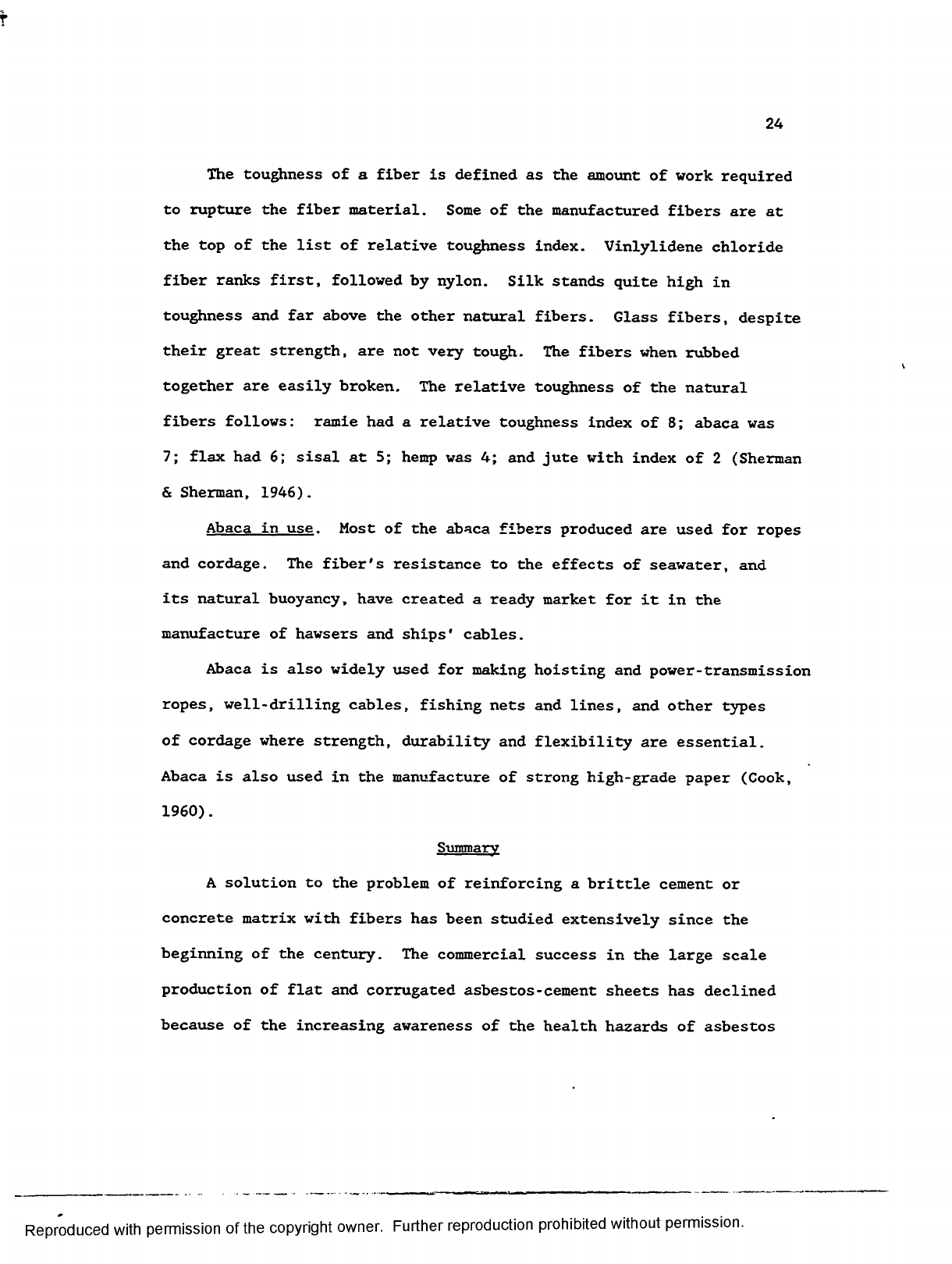
The toughness of a fiber is defined as the amount of wo rk required
to rupture the fiber material. Some of the manufactured fibers are at
the top of the list of relative toughness index. Vinlylidene chloride
fiber ranks first, followed b y nylon. Silk stands quite high in
toughness and far above the other natural fibers. Glass fibers, despite
their great strength, are not very tough. The fibers w hen rubbed
together are easily broken. The relative toughness of the natural
fibers follows: ramie ha d a relative toughness index of 8; abaca was
7; flax ha d 6; sisal at 5; hemp was 4; and jute with index of 2 (Sherman
& Sherman, 1946).
Abaca in u s e . Most of the abaca fibers produced are used for ropes
and cordage. The fiber's resistance to the effects of seawater, and
its natural buoyancy, have created a ready market for it in the
manufacture of hawsers and ships' cables.
Abaca is also widely used for making hoisting and power-transmission
ropes, well-drilling cables, fishing nets and lines, and other types
of cordage where strength, durability and flexibility are essential.
Abaca is also used in the manufacture of strong high-grade paper (Cook,
1960).
Summary
A solution to the problem of reinforcing a brittle cement or
concrete matrix with fibers has been studied extensively since the
beginning of the century. The commercial success in the large scale
production of flat and corrugated asbestos-cement sheets has declined
because of the increasing awareness of the health hazards of asbestos
Reproduced with permission of the copyright owner. Further reproduction prohibited without permission.

fibers. Therefore an alternative product has b ee n actively sought by
many research organizations and other interested parties.
Adequate material characteristics for a substitute to asbestos
fibers has been achieved in the use of glass, steel, and polypropylene
fibers. Some studies have been undertaken in the use of such natural
fibers as sisal, piassava, coconut and bagasse as a reinforcing material
in concrete and cement.
In this researcher's review of related literature, not one piece
of research has been found pertaining to the use of abaca fibers as a
reinforcing material in concrete for the manufacture of low cost
construction materials.
Reproduced with permission of the copyright owner. Further reproduction prohibited without permission.

26
CHAPTER III
METHODOLOGY
This chapter provides a description of the experimental procedures
used in this study, the methods of investigation, the methods of
measurement, the sample size, the concrete mi x design, the equipment
used, the testing procedure and the methods of data analysis.
Procedure of the Study
The first phase in this study was to select the statistical format
to analyze the data obtained. This determined the minimum number of
concrete samples needed for the statistical analysis. The equipment
and machines to be used for testing the concrete samples were decided
upon. The second phase was the actual preparation of the concrete
samples, the testing of these samples, and the analysis of the data
obtained.
In determining the materials to be used in the concrete test
samples, the recommended practices of the American Society for Testing
and Materials (ASTM) and the Concrete Design Manual of the Portland
Cement Association were followed. In addition, the methods and practices
used in related studies where natural vegetable and synthetic fibers
were used in the concrete mix were adapted.
The control group in this study did not contain any fiber
reinforcement in the concrete matrix. The two experimental groups
contained abaca fibers as a reinforcing material. In the first
experimental group, abaca was added with a fiber volume-fraction of 0.2
percent. The second experimental group contained abaca with a fiber
volume-fraction of 0.4 percent. No chemical treatment or additives
Reproduced with permission of the copyright owner. Further reproduction prohibited without permission.

were used in the experimental groups. ASTM specifications required a
minimum of six samples to be cast from a batch and a minimum of two of
the samples be tested. Instead of testing only part of the samples,
as suggested by ASTM, the researcher prepared seven samples for each
experimental batch and the control batch. Each experimental batch and
the control batch was replicated. Each concrete test unit was designed
to contain the following: 14 flexural beams and 14 cylinders for the
control group; 14 flexural beams and 14 cylinders for the first
experimental group with 0.2 percent fiber volume-fraction; and 14
flexural beams and 14 cylinders for the second experimental group with
0.4 percent fiber volume-fraction.
The concrete design mix for the concrete matrix in this study had
a volume ratio of 1.0 part cement to 3.0 parts sand with a maximum
aggregate size of 1/8 inch (3 m m ) . The sand was furnished free of
charge by Manatts Inc. of Waterloo, Iowa. The sand was sieved to remove
unwanted debris which could adversely affect cement hydration and the
ultimate concrete strength. The rotating method of extraction of sand
from the stockpile was used to maintain a homogeneous cross section of
small and large sand.
The Type I Portland cement bagged in 94 pound sacks was selected
from the same batch run. The bags were opened, remixed and used only
when needed during the mixing period. Both sand and cement were measured
by weight.
The abaca fiber used in this study came directly from the
Philippines. The abaca fiber was classified as Class C D and was
described as Good Current. The fibers were cut to short lengths of 1
Reproduced with permission of the copyright owner. Further reproduction prohibited without permission.
28
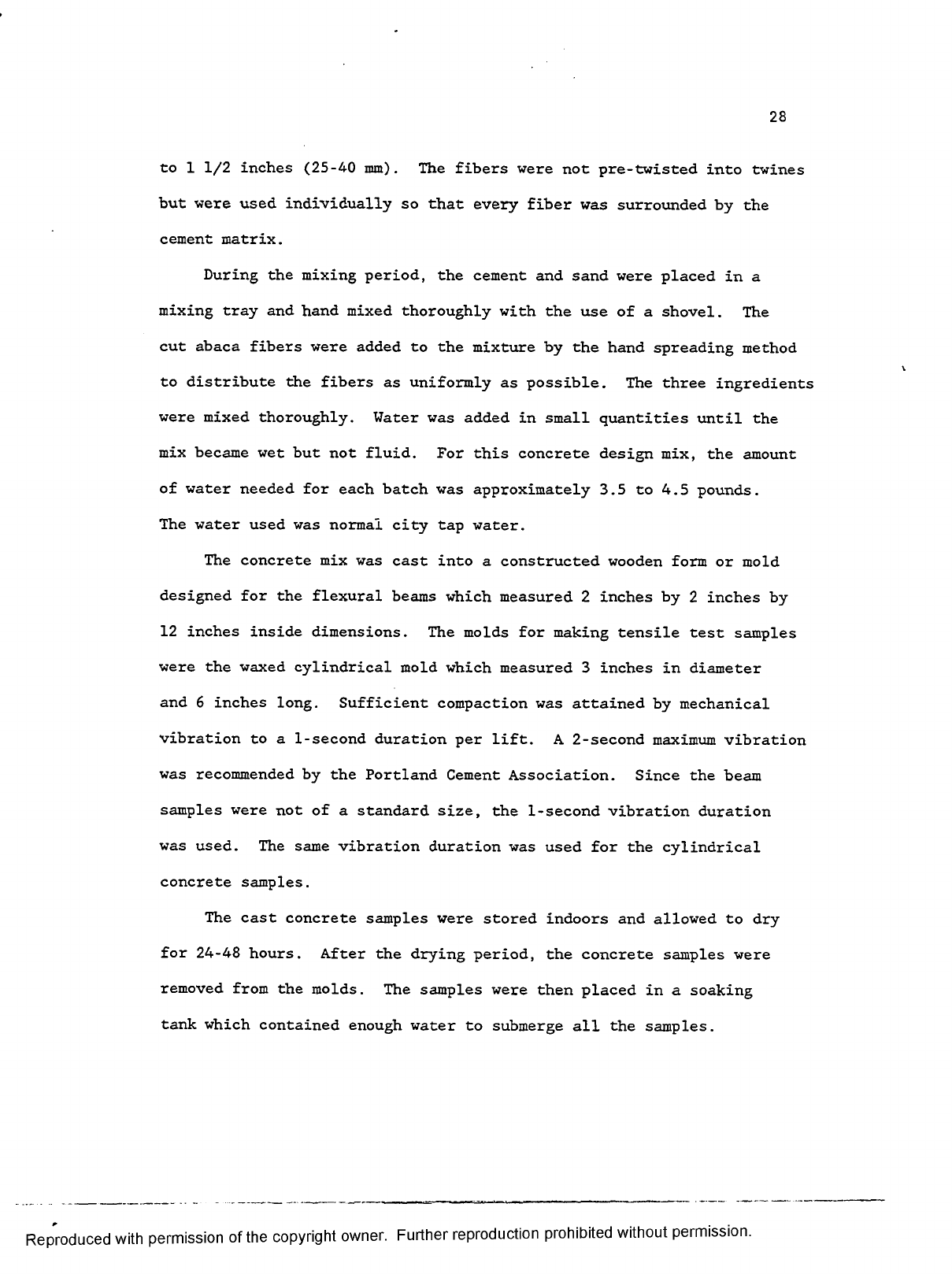
to 1 1/2 inches (25-40 mm). The fibers were not pre-twisted into twines
but were used individually so that every fiber was surrounded by the
cement matrix.
During the mixing period, the cement and sand were placed in a
mixing tray and hand mixed thoroughly with the use of a shovel. The
cut abaca fibers were added to the mixture b y the hand spreading method
to distribute the fibers as uniformly as possible. The three ingredients
were mixed thoroughly. Water was added in small quantities until the
mix became wet but not fluid. For this concrete design mix, the amount
of water needed for each batch was approximately 3.5 to 4.5 pounds.
The water used was normal city tap water.
The concrete mix was cast into a constructed wooden form or mold
designed for the flexural beams which measured 2 inches by 2 inches by
12 inches inside dimensions. The molds for making tensile test samples
were the waxed cylindrical mold which measured 3 inches in diameter
and 6 inches long. Sufficient compaction was attained by mechanical
vibration to a 1-second duration per lift. A 2 -second maximum vibration
was recommended by the Portland Cement Association. Since the beam
samples were not of a standard size, the 1-second vibration duration
was used. The same vibration duration was used for the cylindrical
concrete samples.
The cast concrete samples were stored indoors and allowed to dry
for 24-48 hours. After the drying period, the concrete samples were
removed from the molds. The samples were then placed in a soaking
tank which contained enough water to submerge all the samples.
Reproduced with permission of the copyright owner. Further reproduction prohibited without permission.

29
All samples were cured in water for a full 28 days at room temperature
between 68 degrees to 72 degrees F prior to testing.
The time factor was regulated during the preparation of all test
samples. The mixing process lasted a maximum of 10 minutes. In order
to hold the temperature constant between 68 degrees and 72 degrees F
(room temperature), all preparation and curing of concrete samples was
completed indoors.
There were two types of mechanical measurements employed in this
study; the center-point loading flexural test and the splitting tensile
strength test. The concrete beam samples were tested for their flexural
strengths by using the Vega Low-Range Non-Metallic Testing Machine,
Model 10-K. The Soiltest Versa-Tester, Model 30-K was used for the
splitting tensile strength test of concrete cylinders. The fiber-
reinforced samples were also inspected using the Scanning Electron
Microscope (SEM). The Hitachi S-570 SEM was used to inspect and
determine the bonding between the fibers and the concrete matrix.
The statistical procedures used in analyzing the data obtained
were the t-test and the analysis of variance (ANOVA). The t-test was
used to compare the three groups and determine significant differences.
The ANOVA was used to analyze the mean differences in flexural and
splitting tensile strengths of the three groups.
Methods of Investigation
There were two methods of investigation used in this study. The
first was conducted by using the standard test method for flexural
strength of concrete by using simple beam with center-point loading
(ASTM, 1983a). The second was conducted by using the standard test
Reproduced with permission of the copyright owner. Further reproduction prohibited without permission.
30
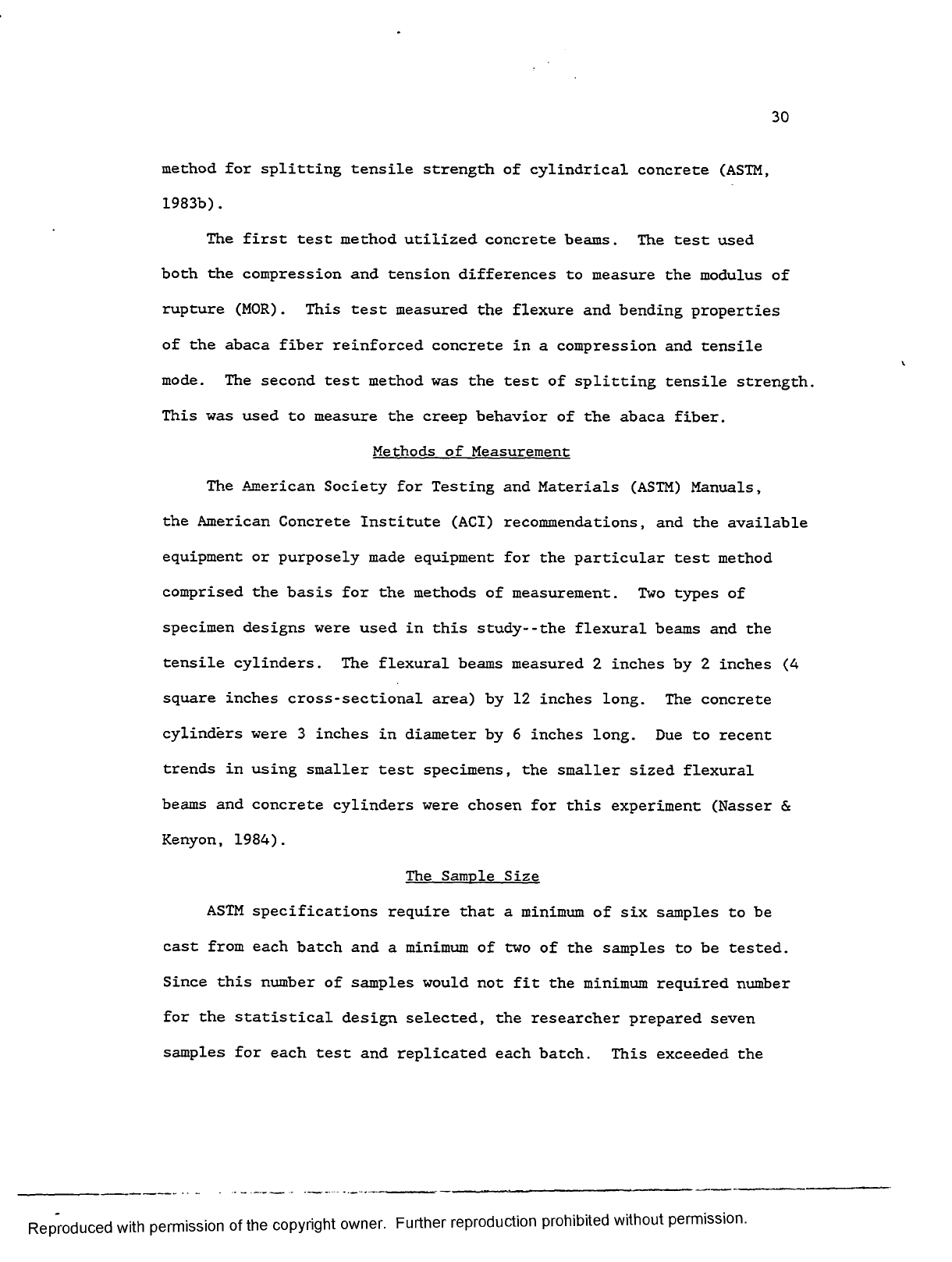
method for splitting tensile strength of cylindrical concrete (ASTM,
1983b).
The first test metho d utilized concrete beams. The test used
both the compression an d tension differences to measure the modulus of
rupture (MOR). This test measured the flexure and bending properties
of the abaca fiber reinforced concrete in a compression and tensile
mode. The second test method was the test of splitting tensile strength.
This was used to measure the creep behavior of the abaca fiber.
Methods of Measurement
The American Society for Testing and Materials (ASTM) Manuals,
the American Concrete Institute (ACI) recommendations, and the available
equipment or purposely made equipment for the particular test method
comprised the basis for the methods of measurement. Two types of
specimen designs were used in this study--the flexural beams and the
tensile cylinders. The flexural beams measured 2 inches by 2 inches (4
square inches cross-sectional area) by 12 inches long. The concrete
cylinders were 3 inches in diameter by 6 inches long. Due to recent
trends in using smaller test specimens, the smaller sized flexural
beams and concrete cylinders were chosen for this experiment (Nasser &
Kenyon, 1984).
The Sample Size
ASTM specifications require that a minimum of six samples to be
cast from each batch and a minimum of two of the samples to be tested.
Since this number of samples would not fit the minimum required number
for the statistical design selected, the researcher prepared seven
samples for each test and replicated each batch. This exceeded the
Reproduced with permission of the copyright owner. Further reproduction prohibited without permission.

31
minimum requirement for ASTM specifications and also improved the
precision of the statistical analysis.
The Concrete Mix Designs
The concrete mix designs used in this study are listed in Tables
1, 2, and 3.
A n inverted slump cone test was performed to determine a mix with
good workability. This test measures the time to empty the abaca fiber
concrete mi x from an inverted slump cone resting 3 inches from the
bottom of a one cubic foot yield bucket. A 1 to 1 1/2 inch diameter
vibrator probe was inserted and allowed to fall to and touch the bottom
of the bucket. The inverted slump cone test for Group II concrete
design mix was within the range of 14 to 17 seconds while for Group
III concrete design mix was within the range of 20 to 24 seconds. A
range of about 11 to 28 seconds for the fiber concrete to empty the
inverted slump cone would indicate a mix with good workability (Henager,
1980) and staying within this range should not affect the strength of
the concrete.
The Equipment
The Vega Low-Range Non-Metallic Testing Machine Model 10-K was
used to test the flexural beams. The Soiltest Versa-Tester Model 30-K
was used to test the concrete cylinders. The Hitachi S-570 Scanning
Electron Microscope was used to examine the failed fiber-reinforced
concrete specimens.
Reproduced with permission of the copyright owner. Further reproduction prohibited without permission.

32
Table 1
Concrete Design Mix I
Group I - Control Group
Cement 6.0 lbs.
Sand 27.0 lbs.
Water 3.5 lbs.
Total Weight 36.5 lbs.
Table 2
Concrete Design Mix II
Group il - 0.2% Fiber Group
Cement
---
Sand
---
Water
---
Total Weight
Fiber
---
6.0 lbs.
27.0 lbs.
4.0 lbs.
37.0 lbs.
30 grams
Table 3
Concrete Design Mix III
Group III - 0.4% Fiber Group
Cement
---
Sand
---
Water
---
Total Weight
Fiber
---
6.0 lbs.
27.0 lbs.
4.5 lbs.
37.5 lbs.
60 grams
Reproduced with permission of the copyright owner. Further reproduction prohibited without permission.

33
Flexural Testing
The test usually applied to fiber-reinforced concrete is the
flexural test. Also called the modulus of rupture (MOR) test, it is
one of the tests recommended by the ACI's Committee 544 on Fiber
Reinforced Concrete (ACI, 1978). It consists of testing a simply
supported beam to failure under a center-point loading method on a 12-
inches span as described in ASTM C 293-79. In this study, a 2-inches
by 2-inches (4-square inches cross-sectional area) b y 12-inches long
concrete bea m was cast for flexural testing. A photograph of the flexure
testing machine with a beam being tested is shown in Figure 1. The
purpose of this test was to determine the calculated values of the
modulus of rupture (MOR) and the modulus of elasticity (E). These
measurements were compared between the experimental groups and the
control group.
After curing the samples for a 2 8 -day duration, the flexural beams
were placed in the Vega Low-Range Non-Metallic Testing Machine. The
bottom support blocks were positioned 1 inch from each end of the
flexural beam. The load-applying block was placed in contact with the
surface of the test specimen at the mid-point between the supports.
The loading system was placed at the center in relation to the applied
force. The loading rate was at a low level which was below the ASTM
recommended 50 pounds per second. Two measuring devices were utilized
in the Vega testing machine. A dial indicator was used to measure
load readings in pounds. Before each specimen was tested, this dial
was calibrated by indexing the dial indicator to zero. This dial was
Reproduced with permission of the copyright owner. Further reproduction prohibited without permission.

— Flexure testing machine with a beam being tested..
Reproduced with permission of the copyright owner. Further reproduction prohibited without permission.

35
designed to measure at 10 pounds interval. The other device was the
mechanical crank which calculated the deflection by the number of turns.
After a beam specimen was properly mounted on the machine and as soon
as pressure was exerted, a zero point in the dial indicator was
established. The researcher calculated and recorded all deflections
to the nearest half turn of the crank. To calculate the modulus of
rupture (MOR) of each test specimen the following formula was used.
3 PI
R
2b d2
where: R = modulus of rupture, psi or MPa,
P •» maximum applied load, lbf or N,
1 = span length, in. or mm,
b = average width of specimen, in. or mm, and
d = average depth of specimen, in. or mm.
The results of the flexural b eam strength tests are shown in
Appendix A. To calculate the modulus of elasticity (E) of the flexural
beams the following formula was used.
4 PI3
dbt3
where: E = modulus of elasticity, psi or kgf/mm2 ,
P = load, lbf or kgf,
1 = length, in. or mm,
d - specimen deflection, in. or mm,
b = specimen width, in. or mm, and
t = specimen thickness, in. or mm.
Reproduced with permission of the copyright owner. Further reproduction prohibited without permission.
36
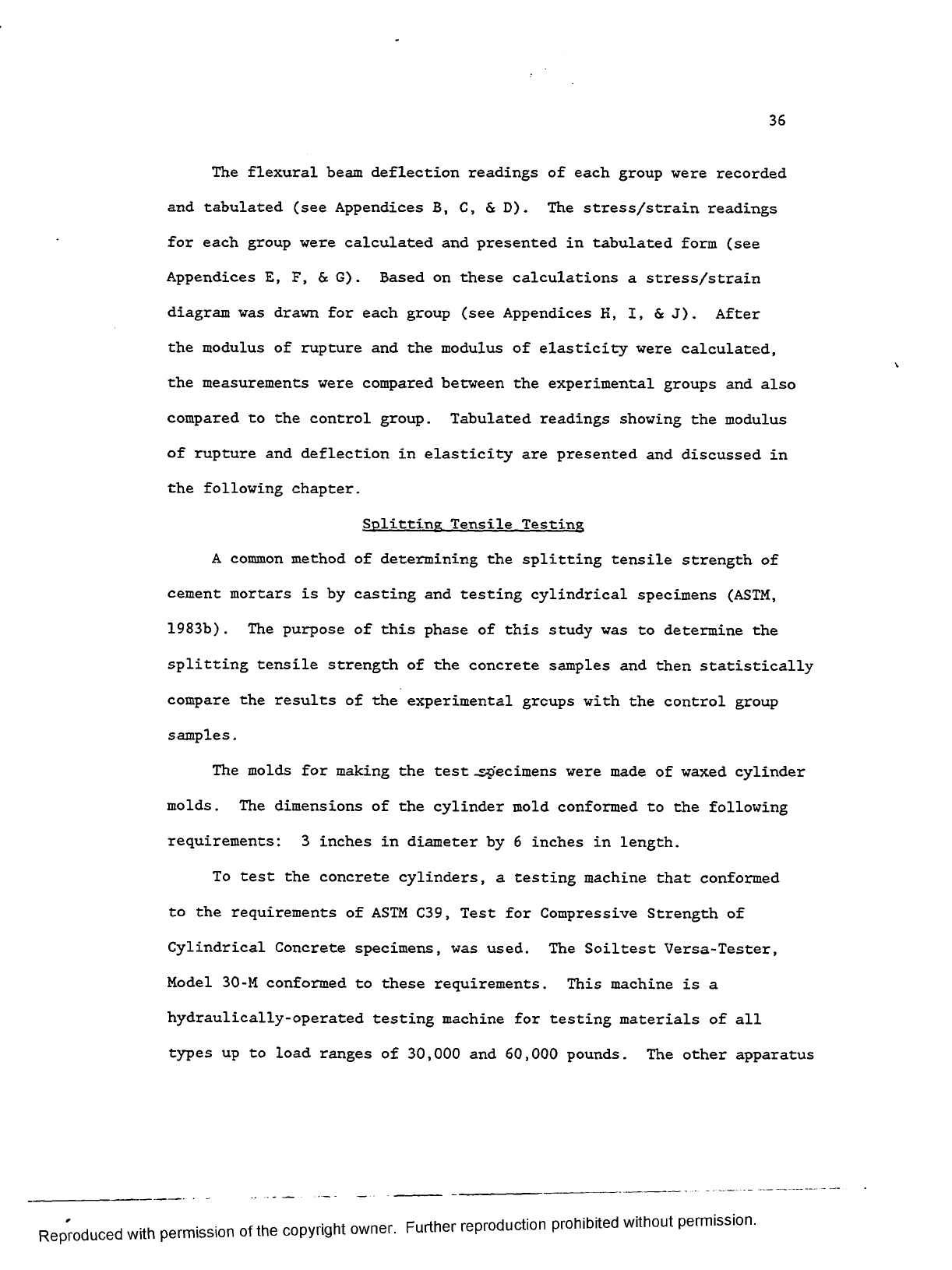
The flexural beam deflection readings of each group were recorded
and tabulated (see Appendices B, C, 6: D ) . The stress/strain readings
for each group were calculated and presented in tabulated form (see
Appendices E, F, 6c G ) . Based on these calculations a stress/strain
diagram was drawn for each group (see Appendices K, I, 6c J). After
the modulus of rupture and the modulus of elasticity were calculated,
the measurements were compared between the experimental groups and also
compared to the control group. Tabulated readings showing the modulus
of rupture and deflection in elasticity are presented and discussed in
the following chapter.
Splitting Tensile Testing
A common method of determining the splitting tensile strength of
cement mortars is b y casting and testing cylindrical specimens (ASTM,
1983b) . The purpose of this phase of this study was to determine the
splitting tensile strength of the concrete samples and then statistically
compare the results of the experimental groups with the control group
samples.
The molds for making the test -specimens were made of waxed cylinder
molds. The dimensions of the cylinder mold conformed to the following
requirements: 3 inches in diameter by 6 inches in length.
To test the concrete cylinders, a testing machine that conformed
to the requirements of ASTM C39, Test for Compressive Strength of
Cylindrical Concrete specimens, was used. The Soiltest Versa-Tester,
Model 30 -M conformed to these requirements. This machine is a
hydraulically-operated testing machine for testing materials of all
types up to load ranges of 30,000 and 60,000 pounds. The other apparatus
Reproduced with permission of the copyright owner. Further reproduction prohibited without permission.

37
utilized for the splitting tensile strength test included a suitable
tool for drawing diametral lines, a supplementary bearing bar, bearing
strips, and an aligning jig. A centering square was used to draw
diametral lines on each end of the specimen. A tempered steel bar
measuring 1 square inch by 7 inches long was prepared as a supplementary
bar. Two bearing strips of 1/8 in. thick plywood approximately 1 in.
wide and 6 inches long were provided for each specimen. A wooden
aligning jig was made which was used to align the supplementary bar
and plywood strips to the center of the specimen and align them directly
beneath the center of thrust of the bearing block. The load was applied
continuously and without shock, at a constant rate until failure of
the specimen. A photograph of the splitting tensile strength testing
machine with a concrete cylinder being tested is shown in Figure 2.
The total maximum load indicated by the testing machine was recorded
and the tensile strength in pound-force per square inch (psi) was
calculated. To calculate the splitting tensile strength of the
specimens, the following formula was used:
2 P
T =
--------
JTld
where: T = splitting tensile strength, psi or kPa,
P = applied load, lbf or kN,
1 = length, in. or mm, and
d — diameter, in. or mm.
The results of calculations for the concrete cylinder splitting
tensile strength tests are shown in Appendix K.
Reproduced with permission of the copyright owner. Further reproduction prohibited without permission.
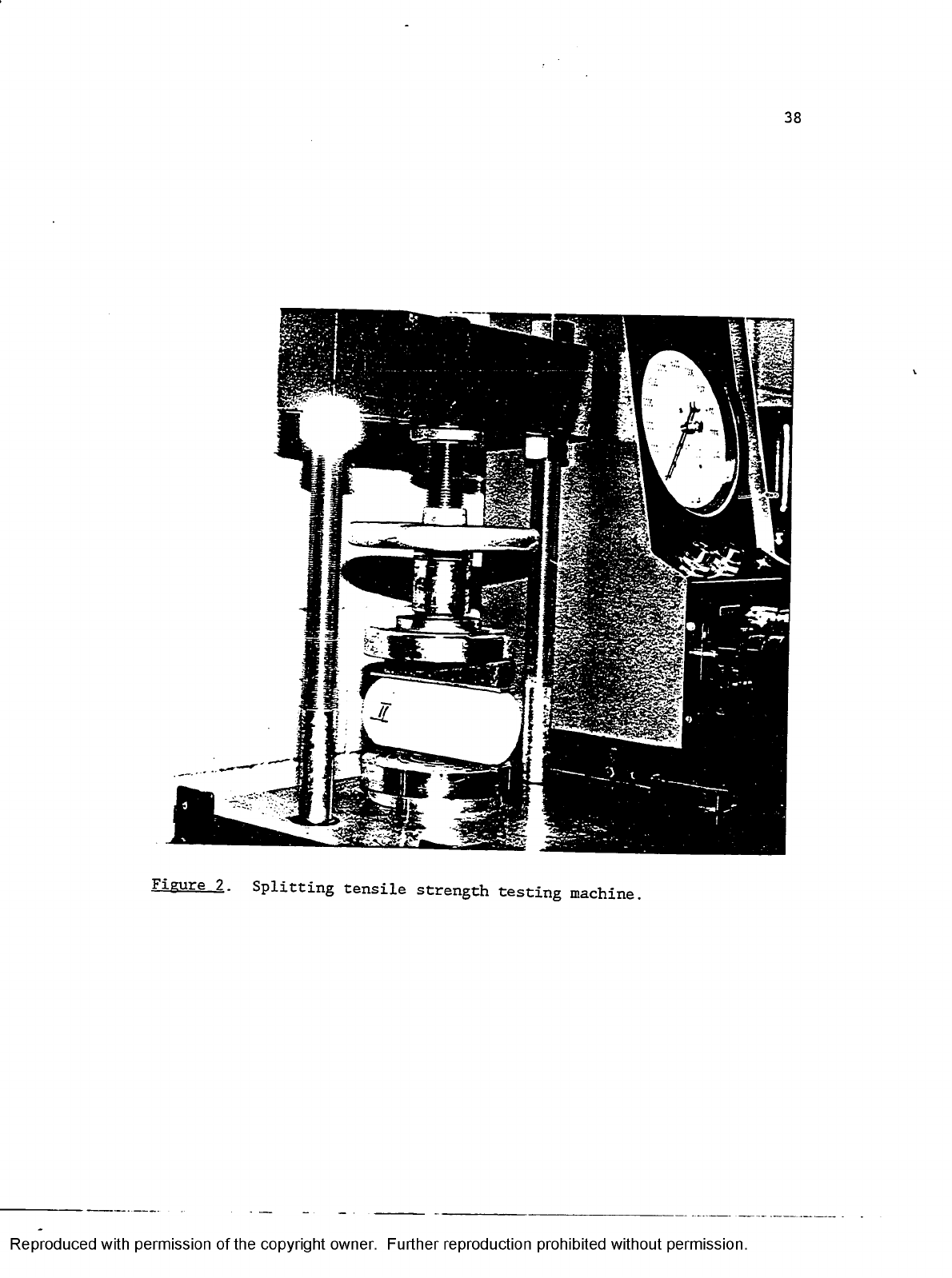
38
Zlgure_2. Splitting tensile strength testing machine.
Reproduced with permission of the copyright owner. Further reproduction prohibited without permission.

39
A table showing raw scores in psi together w ith their means are
presented and discussed in the following chapter. This showed the
comparison of the data gathered from the control group and each of the
experimental groups.
Scanning Electron Microscope Procedure
The Scanning Electron Microscope (SEM) was used to visually examine
the bond between the abaca fibers and the concrete matrix. The SEM
micrographs provided a basis to compare bonding phenomenon in the two
experimental groups.
Scanning Electron Microscope
The scanning electron microscope (SEM) is an apparatus capable of
analyzing surfaces and subsurfaces by using a radiation source that
produces the required illumination and electrons used for image
formation. The wavelengths of the radiation source results in resolution
levels capable of generating high-magnification information. The
scanning electron imaging is concerned with its ability to maintain
focus across a field of view regardless of surface roughness. SEM
micrographs can maintain a three-dimensional appearance of textured
surfaces due to the high depth of field of the scanning instruments.
The combination of high resolution, an extensive range of magnification,
and high depth of field makes the SEM suited for the study of surfaces
and subsurfaces of many materials (Gabriel, 1985).
Permanent SEM images are recorded by photographing the CRT screen
and these photographs are correctly referred to as scanning electron
micrographs. Black-and-white micrographs are the product of an SEM
analysis and is based upon conventional black-and-white photography.
Reproduced with permission of the copyright owner. Further reproduction prohibited without permission.

40
The most common recording medium used is the Polaroid film. Many SEM
microscopes are equipped with 35mm cameras which use conventional black-
and-white film for image recording (Gabriel, 1985).
Sample Preparation and Failure Analysis
To characterize a variety of sample types is a challenge to
microscopic analysis and the analyst should be familiar with various
methods of sample preparation. The minimum magnification of most SEM's
is roughly lOx whereby only a small portion of the specimen surface may
be visible. In order to save valuable time searching for the desired
feature or features, the location of these features are sketched or
photographed to provide more valuable presentation than SEM micrographs
alone. The analyst should also be aware of the objectives of the study
before beginning the sample preparation. An obvious criterion of sample
preparation is its size which should not exceed the size of the specimen
chamber. When a specimen fits into the chamber, the tilt and rotation
stage would not be severely limited. When specimens are too large to
handle, they are cut into small sections. The method of cutting must
not affect the microstructure of the specimen or deform the cut surface.
The cut sections are cleaned of adhering grits or debris before beginning
an analysis. This is a prerequisite for defining the mode of failure
and for a successful SEM imaging. A soft-haired brush or burst of
compressed gas are the least aggressive methods for removing loosely
adhering dust or debris (Gabriel, 1985).
The examination of nonconductive specimens in the SEM is difficult
because the specimens behave like insulators by absorbing electrons
and give them a negative charge. The specimen deflects the electron
Reproduced with permission of the copyright owner. Further reproduction prohibited without permission.

41
beam and degrades the image quality. Image quality can be improved by
treating the specimen surface with organic antistatic agents. Coating
a conductive thin film over the surface could increase the secondary
electron yield and improve image quality on the magnification range of
the SEM. One method commonly used for thin film preparation is sputter
coating and a metallic thin film of gold may be used (Gabriel, 1985).
Failure analyses are conducted to determine how and w hy the specimen
failed. Analyzing fractures reveal the mode of failure which when
combined with all other data identifies the cause of failure (Gabriel,
1985).
Scanning Electron Microscope Procedures
The purpose of the SEM analysis in this study was to examine the
interfacial bonding between the abaca fiber and the concrete matrix
and also visually examine the presence of crystalline growth in the
composite. The SEM micrographs provided photographic records which
were used as basis to compare the interfacial bond of the reinforcing
fiber in the concrete matrix of the experimental groups.
It was decided in this study to conduct an SEM analysis of the
abaca fiber, the flexural beam and concrete cylinder specimens. Random
specimens were selected from each of the experimental groups.
The Hitachi S-570 SEM equipment installed recently at the University
of Northern Iowa was used to examine the specimens and also obtain
micrographs of the samples which were acceptable for the requirements
of this study.
Reproduced with permission of the copyright owner. Further reproduction prohibited without permission.

42
SEM Sample Preparation
A few strands of abaca fibers from a bundle were randomly selected
to be used as specimen for the SEM analysis. The strands were cut to
short lengths and their ends cut diagonally in order that their internal
structure could be examined over the microscope. Micrograph records
were taken showing their cross-sectional and lateral characteristics.
After the flexural beams and concrete cylinders were tested, a
random selection of the failed specimens was made for the SEM analysis
and these specimens were separated from the rest of the sample sets.
The failed fibers from each sample were carefully cleaned by brushing
to remove dust and concrete particles before they were separated from
the failed samples. A pair of tweezers and scissors were used to remove
the failed fibers which were then cataloged and placed in small plastic
bags and stored for future analysis.
The individual specimens were mounted on a metallic disc chosen
for the electron microscope analysis. The samples were placed in a
decompression chamber where they were flushed with argon gas to clean
all surfaces. The final step was the gold coating process which was
accomplished by the sputtering process.
The final step in this procedure was the analysis of the selected
specimens. The specimens were viewed at magnifications of 100 to 700
which enabled the analyst to be familiar with each specimen and determine
the most useful magnification. The last step was to visually examine
the surfaces which revealed the presence of crystalline growth.
Reproduced with permission of the copyright owner. Further reproduction prohibited without permission.

43
CHAPTER IV
EXPERIMENTAL RESULTS AND DISCUSSION
The results of the statistical analysis of the measurements obtained
from testing flexural beams and concrete cylinders are analyzed and
discussed in this chapter. The data analysis consists of tabular
presentation, frequency distribution, means and standard deviations,
and calculated values of modulus of elasticity. Some electron
micrographs of fibers from failed concrete samples are presented and
analyzed. Each of the hypotheses stated in the first chapter was tested
at the .05 level of significance.
Flexural Strength Analysis
The modulus of rupture (MOR) of the three groups of size 14 each
are reported in Appendix L. These values have been arranged in order
of strength from highest to lowest for each group. The MOR values ranged
from 1350.00-810.00 in Group I, from 990.00-753.75 in Group II, and
from 1080.00-675.00 in Group III. The weakest flexural beams failed
at 675.00 PSI and were samples from the 0.4% fiber group. The strongest
flexural beam failed at 1350.00 PSI which was a sample from the control
grou p .
The frequency distribution of the M OR values using an interval of
length 50 is presented in Table 4. The MOR values were least variable
for the 0.2% fiber group and most variable for the 0.4% fiber group.
The means and standard deviations of the distributions of flexural
strength values of the three groups and modulus of elasticity (E) values
are presented in Table 5. The MOR means for Group I, Group II, and
Reproduced with permission of the copyright owner. Further reproduction prohibited without permission.

44
Table 4
Modulus of Rupture Frequency Distribution
Range
Group I Group II Group III
i = 50 Control Group
0.2% Fiber Group
0.4% Fiber Group
1350-1399 1
1300-1349
1250-1299
1
1200-1249
1150-1199 2
1100-1149 3
1050-1099 2 3
1000-1049 2
3
950-999 2
6
900-949 4
1
850-899
1 1
800-849 1
2
750-799
1
4
700-749
650-699 2
N
14 14 14
Reproduced with permission of the copyright owner. Further reproduction prohibited without permission.

45
Group III were 1092.05, 912.05, and 901.57, respectively and the standard
deviations for Groups I through III were respectively 131.38, 72.30,
and 153.77. The modulus of elasticity (E) values as calculated for
Groups I through III were 2.5, 2.7, and 2.9 x 10⁴ , respectively. The
modulus of elasticity of the control group (E = 2.5 x 10⁴ ) was lower
than the elastic modulus of the 0.2% fiber group (E = 2.7 x 10⁴ ) and
the 0.4% fiber group (E = 2.9 x 10⁴ ) . The modulus of elasticity of
the 0.2% fiber group was lower than the elastic modulus of the 0.4%
fiber group.
Table 5
Means and Standard Deviations of MOR Values and Modulus of Elasticity
Values
Group I
Control Group
Group II
0.2% Fiber Group
Group III
0.4% Fiber Group
Means
1092.05 912.05
901.57
S.D.
131.38 72.30
153.77
E x 104
2.5
2.7
2.9
N
14
14
14
The researcher analyzed the MOR values by batch of size seven
each to determine if the mean flexural strength values differed
significantly in each batch. These MO R values have been arranged in
Reproduced with permission of the copyright owner. Further reproduction prohibited without permission.

46
order of strength from highest to lowest for each group. The M O R values
in the first and second batch are reported in Appendix M. The frequency
distribution of the MOR values in each batch using an interval length
of 50 is presented in Appendix N. The means and standard deviations
and their respective modulus of elasticity values are reported in
Appendix 0.
Discussion
The abaca-fiber concrete samples prepared for this study had a
design mix containing small maximum aggregate size of 1/S inch (3mm).
The fiber material was better utilized by a better bond of the strong
and tight matrix which gave efficient protection to the fibers. When
short, chopped abaca fibers of 1-1 1/2 inches (25-40mm) long were added
at random to the concrete matrix, it resulted to some stiffening of the
fresh matrix. This stiffening and some interlocking of fibers eventually
resulted in balling which necessitated the addition of water to keep
the workability of the matrix constant. This need for extra water was
directly related to the fiber volume-fraction of the concrete design mix.
The concrete matrix reinforced with chopped abaca fibers showed a
change in its stress-strain behavior. It was noted that both
unreinforced concrete and the abaca fiber reinforced concrete had slight
degrees of differences in stiffness, strength, and elasticity until
the material cracked. For the abaca fiber reinforced concrete, the
stress at the first cracking was somewhat lower than for the unreinforced
matrix. After the point where the material cracked was reached, the
stress for the unreinforced concrete dropped drastically resulting to
the collapsing of the material. For the abaca fiber reinforced concrete,
Reproduced with permission of the copyright owner. Further reproduction prohibited without permission.
47
the stress dropped to a lower level until the level of strain was reached
before the material finally fractured.
It was noted that the mean flexural strength of the control group
samples was higher than the 0.2% and 0.4% fiber groups. Since the
fiber added was not chemically treated nor any admixture included in
the matrix, one probable explanation for this outcome could be the
negative effect of the fibers on the cement hydration. The more
significant finding, however, was shown from the calculations of the
modulus of elasticity values. It was noted that the 0.4% fiber group
ha d the highest modulus of elasticity value, followed by the 0 .2 % fiber
group and the control group obtained the lowest value. This indicated
that the addition of abaca fibers as a secondary reinforcement material
to the concrete matrix performed their function as crack arresters and
crack deflectors. The fibers tend to stop the cracks from propagating
by holding the concrete matrix together so that cracks cannot spread
wider or grow longer. Since the fibers were closely spaced at random
angles they reinforced the matrix in all directions. The fibers not
only compensated for the lower flexural and tensile strength of concrete
but improved the elastic strength of the composite material.
Statistical Analysis of Flexural Strength
The t-tests were used to compare the mean flexural strength values
of the three groups to determine significant differences and investigate
specific hypotheses . The One Way Analysis of Variance (ANOVA) was
used to analyze the mean differences in flexural strength of the three
groups. This technique allowed the researcher to determine whether the
Reproduced with permission of the copyright owner. Further reproduction prohibited without permission.

48
experimental treatments have produced significant differences among
the calculated means.
The results of t-tests used to compare the three groups are reported
in Table 6 . In the first t-test, the mean modulus of rupture value of
Group I (M - 1092.05) was significantly higher than Group II (M -
912.05), t(26) = 4.49, p < .01. In the second t-test, the mean modulus
of rupture value of Group I (M - 1092.05) was significantly higher
than Group III (M = 901.57), t(26) = 3 . 5 2 , p < .01. In the third t-
test, however, the mean modulus of rupture value of Group II (M = 912.05)
was not significantly higher than Group III (M = 901.57), t(26) = 0.23,
p > .05.
Table 6
t-test ("Three Groups) on Flexural Strengths (MOR')
Compare df t
P
Group I and Group II
26 4.49
< .01
Group I and Group III
26
3.52
< .01
Group II and Group III
26 0.23
> .05
The ANOVA summary presented in Table 7 shows the analysis of
variance among the mean differences in flexural strength values of the
three groups. The result indicated a significant mean difference in
Reproduced with permission of the copyright owner. Further reproduction prohibited without permission.

49
flexural strength among the three groups and was statistically
significant, F (2, 39) = 10.44, £ < .01.
Table 7
One Wav ANOVA (Three Groups) on Flexural Strength ('MOR')
Source
df
Sum Squares
Variance Estimate F
P
Between-groups 2
321035.50
160517.75
10.44
< .01
Within-groups 39
599713.22 15377.26
Total
41
920748.72
The results of t-tests used to compare the three groups in the
first and second batch are reported in Appendix P. The ANOVA summaries
for the first and second batch are reported in Appendix Q.
Splitting Tensile Strength Analysis
The splitting tensile strength (T) values of the three groups of
size 14 each are reported in Appendix R. These values have been arranged
in order of strength from highest to lowest for each group. The T
values ranged from 645.46-542.89 in Group I, from 680.83-503.99 in
Group II, and from 618.93-433.25 in Group III. The weakest cylinders
failed at 433.25 PSI and were samples from the 0.4% fiber group. The
strongest cylinder failed at 680.83 PSI and was a sample from the 0.2%
fiber group.
Reproduced with permission of the copyright owner. Further reproduction prohibited without permission.

50
The frequency distribution of the T values using an interval length
of 20 is presented in Table 8 . The values were least variable for the
Table 8
Splitting Tensile Strength Frequency Distribution
Range
i = 20
Group I
Control Group
Group II
0.2% Fiber Group
Group III
0.4% Fiber Group
680-699
1
660-679
640-659
1
1
620-639
1
600-619 4
1
1
580-599
1 3
560-579 3
4
540-559
4
1
2
520-539
2 1
500-519
1 4
480-499
1
460-479
440-459
2
420-439
3
N
14
14
14
Reproduced with permission of the copyright owner. Further reproduction prohibited without permission.

51
control group, followed by the 0 .2 % fiber group and more variable for
the 0.4% fiber group.
The means and standard deviations of the distributions of splitting
tensile strength values of the three groups are presented in Table 9.
The T means for Group I, Group II, and Group III were 584.49, 577.95,
and 499.06 PSI, respectively and the standard deviations for Groups I
through III were respectively 32.09, 44.77, and 55.47.
Table 9
Means and Standard Deviations of T Values
Group I
Control Group
Group II
0.2% Fiber Group
Group III
0.4% Fiber Group
Means 584.49 577.95 499.06
S.D.
32.09
44.77
55.47
N
14 14
14
The researcher also analyzed the T values by batch of size seven
each to determine if the mean splitting tensile strength values differed
significantly in each batch. These T values have been arranged in
order of strength from highest to the lowest for each group. The T
values in the first and second batch are reported in Appendix S. The
frequency distribution of the splitting tensile strength (T) values in
each batch using an interval length of 20 is presented in Appendix T.
Reproduced with permission of the copyright owner. Further reproduction prohibited without permission.

52
The means and their respective standard deviations are reported in
Appendix U.
Statistical Analysis of Splitting Tensile Strength
The t-tests were used to compare the mean splitting tensile strength
values of the three groups and investigate specific hypotheses. The
One Way Analysis of Variance (ANOVA) was used to analyze the m ean
differences in splitting tensile strength of the three groups.
The results of t-tests used to compare the three groups are reported
in Table 10. In the first t-test, the mean splitting tensile strength
value of Group I (M = 584.49) was not significantly higher than the
mean splitting tensile strength value of Group II (M = 577.95), t(26)
= 0 . 4 4 , £ > .05. In the second t-test, the mean splitting tensile
strength value of Group I (M = 584.49) was significantly higher than
the mean splitting tensile strength value of Group III (M = 499.06),
t(26) = 4.99, £ < .01. In the third t-test, the mean splitting tensile
strength value of Group II (M = 577.95) was significantly higher than
the mean splitting tensile strength value of Group III (M = 499.06),
t(26) = 4.14, £ < .01.
The ANOVA summary presented in Table 11 shows the analysis of
variance among the mean differences in splitting tensile strength values
of the three groups. The results indicated significant mean differences
in splitting tensile strength among the three groups, F (2, 39) = 15.53,
£ < .01.
The results of t-tests used to compare the three groups in the
first and second batch are reported in Appendix V. The ANOVA summaries
for the first and second batch are reported in Appendix W.
Reproduced with permission of the copyright owner. Further reproduction prohibited without permission.

53
Table 10
t-test (Three Groups') on Splitting Tensile Strengths (T)
Compare df t
P
Group I and Group II
26 0.44
> .05
Group I and Group III
26
4.99 < .01
Group II and Group III
26 4.14 < .01
Table 11
One Wav ANOVA
(Three Grouos') on Solittine Tensile Strengths (T^
Source
df
Sum Squares Variance Estimate F p
Between-groups
2 63295.09
31647.54 15.53 < .01
Within-groups
Total
39
41
79451.75
142746.84
2037.22
Testing of Hypotheses
At the beginning of this investigation it was decided to test the
hypotheses through statistical analysis of the mechanical measurements
employed in this study. These analyses were ascertained from the
strength values of the flexural beams and the concrete cylinders.
Reproduced with permission of the copyright owner. Further reproduction prohibited without permission.

54
Hypothesis 1: The mean flexural strength of the control group
concrete samples would not differ significantly from the mean flexural
strength of samples containing the abaca fiber with a volume-fraction
of 0.2 percent. The statistical analysis showed that the difference
in mean flexural strength (MOR) between the control group and the 0.2%
fiber group was statistically significant, (t =* 4.49, < .01). Based
on the result of the analysis, hypothesis 1 was rejected.
Hypothesis 2: The mean flexural strength of the control group
concrete samples would not differ significantly from the mean flexural
strength of samples containing the abaca fiber with a volume-fraction
of 0.4 percent. The statistical analysis indicated that the difference
in mean flexural strength (MOR) between the control group and the 0.4%
fiber group was statistically significant, (t = 3.84, £ < .01). On
the basis of statistical analysis, hypothesis 2 was rejected.
Hypothesis 3: The mean flexural strength of concrete samples
containing the abaca fiber with a volume-fraction of 0 .2 percent would
not differ significantly from the mean flexural strength of samples
containing abaca fiber with a volume-fraction of 0.4 percent. The
statistical analysis showed that the mean flexural strength of the
0 .2 % fiber group was not significantly higher than the mean flexural
strength of the 0.4% fiber group and the difference was not statistically
significant, (t = 0.23, > .05). On this basis, hypothesis 3 was not
rejected.
Hypothesis 4: The mean flexural strengths of the control group,
the 0.2 percent fiber group, and the 0.4 percent fiber group concrete
samples would not differ significantly. The result of the analysis
Reproduced with permission of the copyright owner. Further reproduction prohibited without permission.

55
showed that there were significant differences among the mean flexural
strengths of the control group, the 0 .2 % fiber group, and the 0 .4 %
fiber group, and these differences were statistically significant, (F
= 10.44, p < .01). Based on the result of the analysis, hypothesis 4
was rejected.
Hypothesis 5: The mean splitting tensile strength of the control
group concrete samples would not differ significantly from the mean
splitting tensile strength of samples containing the abaca fiber with
a volume-fraction of 0.2 percent. The statistical analysis showed
that the mean splitting tensile strength of the control group was not
significantly higher than the mea n splitting tensile strength of the
0 .2% fiber group and the difference was not statistically significant
(t = 0.44, p > .05). Based on this analysis, hypothesis 5 was not
rejected.
Hypothesis 6 : The mean splitting tensile strength of the control
group concrete samples would not differ significantly from the mean
splitting tensile strength of samples containing the abaca fiber with
a volume-fraction of 0.4 percent. The statistical analysis showed
that the control group had a higher mean splitting tensile strength
than the 0.4% fiber group and the difference was statistically
significant, (t =* 4.99, p < .01). On this basis, hypothesis 6 was
rejected.
Hypothesis 7: The mean splitting tensile strength of concrete
samples containing abaca fiber with a volume-fraction of 0 . 2 percent
would not differ significantly from the mean splitting tensile strength
of samples containing abaca fiber with a volume-fraction of 0.4 percent.
Reproduced with permission of the copyright owner. Further reproduction prohibited without permission.

56
The analysis of mean splitting tensile strength indicated that the
0.2% fiber group h a d a higher me an value than the 0.4% fiber group.
The mean difference was statistically significant (t = 4.14, p < .01),
therefore, hypothesis 7 was rejected.
Hypothesis 8 : The mean splitting tensile strengths of the control
group, the 0.2 percent fiber group, and the 0.4 percent fiber group
concrete samples would not differ significantly. The statistical
analysis showed significant differences among the mean splitting tensile
strengths of the control group, the 0.2% fiber group, and the 0.4%
fiber group. These mean differences were statistically significant (F
= 15.33, p < .01) to reject hypothesis 8 .
Scanning Electron Microscope Analysis
It was stated in the previous chapters that the bonding phenomena
between the reinforcing fiber and concrete matrix could be examined
and analyzed by the Scanning Electron Microscopy (SEM) technique.
While not a part of the study initially, the SEM micrographs could
provide a basis to compare the bonding phenomena between the abaca
fiber and concrete mix in the two experimental groups. The analysis
of the abaca natural fiber and some specimens from failed flexural
beam and concrete cylinder test samples are presented.
Abaca Natural Fiber
A strand of abaca fiber in its natural state was analyzed at a
relatively low magnification of llOx. The fiber was cut at its end to
show the internal structure or substructure. Figure 3 shows the
structure of the fiber which was irregularly round or oval in shape.
Reproduced with permission of the copyright owner. Further reproduction prohibited without permission.

The fiber was composed of fiber bundles which were a series of peculiarly
thick, strongly silicified plates.
Figure 3 . Structure of abaca fiber.
Reproduced with permission of the copyright owner. Further reproduction prohibited without permission.

58
The surface of the fiber as shown in Figure 4 was examined at a
relatively high magnification of 700x. The surface appeared to be
lustrous, smooth, with fiber bundles stretching mostly in the axial
direction.
700x 43um
Figure 4 . Abaca fiber surface.
Reproduced with permission of the copyright owner. Further reproduction prohibited without permission.

59
Abaca Fibers taken from Failed Concrete Specimens
An abaca fiber that was mixed in concrete at 0.2% fiber vol ume -
fraction is shown in Figure 5. This specimen was examined using the
SEM at 700x magnification. The fiber surface contained some dehydration
products attached to the grooves of the surface. These dehydration
products were in the form of CH (calcium hydroxide) crystals which were
relatively small in size and are characterized by having sharp edges.
The growth of these crystals on the fiber surface was not massive.
K
I
700x
43um
Figure 5 . Abaca fiber from 0.2% volume-fraction concrete.
Reproduced with permission of the copyright owner. Further reproduction prohibited without permission.

60
The topography of the fiber surface of a fiber taken from the
concrete specimen containing 0.4% fiber volume-fraction is shown in
Figure 6 . This specimen was analyzed at 700x magnification. The surface
of the fiber contained massive CH crystalline precipitates. These
700x 43um
Figure 6 . Abaca fiber from 0.4% volume-fraction concrete.
Reproduced with permission of the copyright owner. Further reproduction prohibited without permission.

61
crystalline growth formed a layer of crystal crusts lodged into the
grooves of the fiber. A crack started through the center of the thick
crust bu t did not extend through the fiber is also shown in this electron
micrograph illustrating the crack arrest phenomenon of fiber
reinforcements.
The fiber volume-fraction in a concrete matrix is shown to have
influenced the growth of the dehydration products on both its density
and distribution. At 0.2% volume-fraction, the dehydration product was
scarce. A t 0.4% volume-fraction, massive crystalline products were
found on the fiber surface and grooves. The differences in dehydration
products density was attributed to the presence of more gaps between
the fiber and matrix in the 0.2% volume-fraction. In the 0.4% volume-
fraction, however, the gaps were not as much because the fibers were
closer to each other. This accounted for the increased rate of
dehydration which resulted in massive accumulation of dehydration
products in the 0.4% fiber concrete. The rate of precipitation of
these crystals in the 0.4% fiber concrete was also accelerated whereby
the crystals did not cluster as much as those found in the 0 .2 % volu me-
fraction. It was observed that the higher rate of precipitation resulted
in lower crystalline growth rate. This low crystal growth rate in
turn resulted in the formation of smaller crystals that accumulated in
mass. This phenomenon could increase the strength of individual fibers
and make them more difficult to break.
A n important function in fiber reinforcement is for the fiber to
act as a crack-arrest mechanism as referred to earlier. This function
was clearly demonstrated in Figure 7. This figure shows a fiber within
Reproduced with permission of the copyright owner. Further reproduction prohibited without permission.

62
a concrete matrix with cracks coming from different directions. The
cracks ran under the aggregates instead of penetrating through them
but were eventually stopped by the fiber. This clearly demonstrated
that the individual fiber acted as a crack arrestor.
200 x 150um
Figure 7 . Abaca fiber as a crack-arrest mechanism.
Reproduced with permission of the copyright owner. Further reproduction prohibited without permission.

63
Another important phenomenon known as fiber pull-out was clearly
demonstrated in the specimen shown in Figure 8 . Fiber pull-out resulted
when the load or strain on the fiber was too much whereby the fiber
&
17 Ox
176um
Figure 8 . Fiber pull-out phenomenon.
Reproduced with permission of the copyright owner. Further reproduction prohibited without permission.

64
pulled out of the matrix and broke the bond between the fiber and matrix.
This break in bond was indicated by the gap created between the fiber
and the concrete matrix. It was noted also that massive precipitates
of small sized crystals formed on the fiber surface and grooves. Some
cracks in the matrix were present but were stopped by the individual
fiber.
The specimen shown in Figure 9 clearly demonstrated two more
significant aspects in fiber reinforcement. The fiber pull-out
1
lOOx
. 30mm
Figure 9 . Fiber pull-out, crack arrest and crack,
energy deflection phenomena
Reproduced with permission of the copyright owner. Further reproduction prohibited without permission.

phenomenon was again demonstrated which left a gap betw een the fiber
and matrix indicating that the fiber was shaken loose. Dehydration
products are again found all over the fiber surface and grooves. Another
important phenomenon that was of tremendous value in this analysis was
the aspect of crack energy deflection. There were three cracks in the
matrix originating from three different levels. These cracks extended
to the fiber and broke part of the fiber bundles. Whe n the fiber bundles
were partially broken, the crack energy was deflected from the horizontal
towards the axial direction of the fiber. This clearly demonstrated
that the fiber not only acted as a crack arrestor but also deflected
the direction of the crack. This aspect weakened the crack energy
because some of the energy was absorbed and the crack was deflected
and eventually stopped. This could contribute to the strength of or
even some localized ductility in the concrete matrix.
Reproduced with permission of the copyright owner. Further reproduction prohibited without permission.

66
CHAPTER V
SUMMARY, CONCLUSIONS, AND RECOMMENDATIONS
This chapter provides a summary of findings, conclusions of the
study, and recommendations.
Restatement of the Problem and Purpose
The problem of this study was to analyze the flexural and splitting
tensile strengths of concrete composites using the abaca fiber as a
reinforcing material. The purpose was to demonstrate ho w various volume-
fractions of the abaca fiber in the mix could affect the mechanical
properties of the concrete composite.
The following hypotheses were considered:
1. The mean flexural strength of the control group samples would
not differ significantly from the mean flexural strength of the 0 .2%
fiber group samples.
2. The mean flexural strength of the control group samples would
not differ significantly from the mean flexural strength of the 0.4%
fiber group samples.
3. The mean flexural strength of the 0.2% fiber group samples
would not differ significantly from the mean flexural strength of the
0.4% fiber group samples.
4. The mean flexural strengths of the control group, the 0.2%
fiber group, and the 0.4% fiber group samples would not differ
significantly.
5. The mean splitting tensile strength of the control group samples
would not differ significantly from the mean splitting tensile strength
of the 0 .2% fiber group samples.
Reproduced with permission of the copyright owner. Further reproduction prohibited without permission.

67
6 . The mean splitting tensile strength of the control group samples
would not differ significantly from the mean splitting tensile strength
of the 0.4% fiber group samples.
7. The mean splitting tensile strength of the 0.2% fiber group
samples would not differ significantly from the mean splitting tensile
strength of the 0.4% fiber group samples.
8 . The mean splitting tensile strengths of the control group,
the 0.2% fiber group, and the 0.4% fiber group samples would not differ
significantly.
Summary of Findings
The mean flexural strength (MOR) of the control group (M = 1092.05)
was significantly higher than the mean flexural strength of the 0 .2 %
fiber group (M = 912.05). Further analysis revealed that the addition
of abaca fiber to the concrete mix at 0.2 percent volume-fraction
decreased the mean flexural strength by 16.48 percent when compared to
the mean flexural strength of the control group.
The modulus of elasticity (E) of the control group (E = 2.5 x
10 4 ) was lower than the modulus of elasticity of the 0 .2% fiber group
(E = 2.7 x 10⁴ ) . This indicated that the addition of abaca fiber to
the concrete mix at 0.2 percent volume-fraction increased the elastic
modulus by 7.41 percent when compared to the elastic modulus of the
control group. This showed that the inclusion of abaca fibers as
reinforcing agents can increase the ductility of the concrete matrix.
The mean flexural strength (MOR) of the control group (M = 1092.05)
was significantly higher than the mean flexural strength of
Reproduced with permission of the copyright owner. Further reproduction prohibited without permission.
68
the 0.4% fiber group (M — 901.57). Further analysis revealed that the
addition of abaca fiber to the concrete mix at 0.4 percent volume-
fraction decreased the mean flexural strength b y 17.44 percent when
compared to the mean flexural strength of the control group.
The modulus of elasticity (E) of the control group (E = 2.5 x
104 ) was lower than the modulus of elasticity of the 0.4% fiber group
(E = 2.9 x 10⁴ ) . Additional analysis revealed that the addition of
abaca fiber to the concrete mix at 0.4 percent volume-fraction increased
its elastic modulus by 13.79 percent when compared to the elastic modulus
of the control group. This result indicated that increasing the fiber
volume-fraction in the concrete mix could result in increased ductility
of the matrix.
The mean flexural strength (MOR) of the 0.2% fiber group (M =
912.05) was higher than the mean flexural strength of the 0.4% fiber
group (M = 901.57) but the difference was not statistically significant.
Further analysis revealed that increasing the fiber volume-fraction in
the concrete mix from 0.2 to 0.4 percent decreased the mean flexural
strength by only 1.15 percent.
The modulus of elasticity (E) of the 0.2% fiber group (E = 2.7 x
104 ) was lower than the modulus of elasticity of the 0.4% fiber group
(E = 2.9 x 10⁴ ) . Additional analysis revealed that increasing the
fiber volume-fraction in the concrete mix from 0.2 to 0.4 percent
increased the elastic modulus by 6.90 percent.
The difference in mean flexural strengths (MOR) among the control
group (M = 1092.05), the 0.2% fiber group (M - 912.05), and the 0.4%
fiber group (M = 901.57) was statistically significant. Further analysis
Reproduced with permission of the copyright owner. Further reproduction prohibited without permission.

69
revealed that the addition of abaca fibers at volume-fractions of 0.2
and 0.4 percent decreased the mean flexural strengths of the concrete
mix by 16.48 and 17.44 percent respectively when compared to the mean
flexural strength of the control group.
The difference in modulus of elasticity (E) among the control
group (E = 2.5 x 10^), the 0.2% fiber group (E - 2.7 x 10^), and the
0.4% fiber group (E - 2.9 x 10^) showed an increasing trend. Further
analysis revealed that the addition of abaca fibers at volume-fractions
of 0.2 and 0.4 percent increased the elastic modulus by 7.41 and 13.79
percent, respectively when compared to the elastic modulus of the control
group. These results showed that the increasing trend in ductility of
the concrete matrices was influenced by the increase in fiber volume-
fractions in the concrete mix.
The mean splitting tensile strength (T) of the control group (M =
584.49) was higher than the mean splitting tensile strength of the
0.2% fiber group (M = 577.95) but the difference was not statistically
significant. The addition of abaca fiber to the concrete mix at 0.2
percent volume-fraction decreased the mean splitting tensile strength
by only 1 .12 percent when compared to the mean splitting tensile strength
of the control group.
The mean splitting tensile strength (T) of the control group (M =
584.49) was significantly higher than the mean splitting tensile strength
of the 0.4% fiber group (M — 499.06). The addition of abaca fiber to
the concrete mix at 0.4 percent volume-fraction decreased the mean
splitting tensile strength by 14.62 percent when compared to the mean
splitting tensile strength of the control group.
Reproduced with permission of the copyright owner. Further reproduction prohibited without permission.

70
The mean splitting tensile strength (T) of the 0.2% fiber group
(M = 577.95) was higher than the mean splitting tensile strength of
the 0.4% fiber group (M = 499.06). Further analysis revealed that
increasing the fiber volume-fraction in the concrete mix from 0 . 2 to
0.4 percent decreased the mean splitting tensile strength b y 13.65
perc en t .
The difference in mean splitting tensile strengths (T) among the
control group (M ~ 584.49), the 0.2% fiber group (M - 577.95), and the
0.4% fiber group (M = 499.06) was statistically significant. The
addition of abaca fiber at 0 .2 percent volume-fraction decreased the
mean splitting tensile strength by 1.12 percent while at 0.4 per cent
volume-fraction the mean splitting tensile strength decreased b y 14.62
percent.
The findings in the SEM analysis are as follows:
1. The abaca fiber was composed of fiber bundles with peculiarly
thick, strongly silicified plates. The structure of the fiber was
irregularly round or oval in shape. The fiber surface appeared to be
smooth, lustrous, with fiber bundles stretching mostly in the axial
direction.
2. The surface of the abaca fiber added at 0.2 percent volume-
fraction in the concrete mix contained dehydration products in the
form of CH (calcium hydroxide) crystals which were relatively small in
size and were characterized by having sharp edges. The growth of these
crystals was not massive. The topography of the abaca fiber surface
added at 0.4 percent volume-fraction in the concrete mix contained
massive CH crystalline precipitates.
Reproduced with permission of the copyright owner. Further reproduction prohibited without permission.

71
3. The increase in fiber volu me-fraction of abaca influenced the
growth of the dehydration products on both its density and distribution.
At 0.2 percent volume-fraction, the dehydration product was scarce
whereas at 0.4 percent volume-fraction, massive crystalline products
were found.
4. The crack-arrest function in fiber reinforcement was clearly
demonstrated by fibers stopping the propagation of cracks in the matrix
and then deflecting the crack energy towards the axial direction of
the fibers. This aspect weakened the crack energy and may have
contributed to the strength of some localized ductility in the matrix.
5. The fiber pull-out phenomenon was demonstrated resulting in a
break in the bond between the fiber and the concrete matrix whereby
the fiber was shaken loose. The fiber pulled out from the matrix when
the applied load was too much for it to absorb.
Conclusions
By examining the findings of the data analysis, the following can
be concluded:
1. The control group samples which contained no fiber reinforcement
ha d significantly higher mean flexural strength (MOR) than the mean
flexural strengths of group samples containing abaca fibers with volume-
fractions of 0.2 and 0.4 percent. The addition of short, untreated,
and randomly distributed abaca fibers to the concrete mix with v olume -
fractions of 0.2 and 0.4 percent significantly decreased the mean
flexural strength by 16.48 and 17.44 percent, respectively, when compared
to the mean flexural strength of the control group. The difference in
mean flexural strengths between the 0.2 and 0.4 percent fiber volume-
Reproduced with permission of the copyright owner. Further reproduction prohibited without permission.

fraction group samples showed a decrease in flexural strength by only
1.15 percent. Increasing the fiber volume-fraction of abaca in the
concrete mix decreased the mean flexural strength of the concrete matrix.
2. The control group samples which contained no fiber reinforcement
had lower modulus of elasticity (E) value than the modulus of elasticity
of group samples containing abaca fibers with volume-fractions of 0.2
and 0.4 percent. The addition of abaca fibers to the concrete mix
increased the elastic modulus b y 7.41 percent in the group samples
containing fibers at 0.2 percent volume-fraction. The addition of
abaca fibers to the concrete mix at 0.4 percent volume-fraction increased
the elastic modulus b y 13.79 percent when compared to the elastic modulus
of the control group. The difference in modulus of elasticity values
between the 0.2 and 0.4 percent fiber volume-fractions showed an increase
in elastic modulus by 6.90 percent. Increasing the volume-fraction of
abaca fiber in the concrete mix increased the modulus of elasticity of
the concrete matrix which improved the ductility of the concrete
composite.
3. The control group samples which contained no fiber reinforcement
had higher mean splitting tensile strength (T) than the mean splitting
tensile strengths of group samples containing abaca fibers with volume-
fractions of 0.2 and 0.4 percent. The addition of abaca fibers in the
concrete mix at 0.2 percent volume-fraction decreased the mean splitting
tensile strength by only 1.12 percent. The addition of abaca fibers
with volume-fraction at 0.4 percent decreased the mean splitting tensile
strength by 14.62 percent when compared to the mean splitting strength
of the control group. The difference in mean splitting tensile strength
Reproduced with permission of the copyright owner. Further reproduction prohibited without permission.

73
between the 0.2 and 0.4 percent volume-fraction of abaca fibers in the
concrete mix decreased the mean splitting tensile strength by 13.65
percent. Increasing the volume-fraction of abaca fiber in the concrete
mix decreased the mean splitting tensile strength of the concrete matrix.
4. The abaca fiber can be an effective reinforcing agent in the
concrete matrix acting as a crack-arrest mechanism by stopping the
propagation of cracks and b y deflecting and absorbing some of the crack
energy. This crack arrest function can contribute to the strength of
some localized ductility in the concrete matrix.
5. The increase in fiber volume-fraction of abaca influenced the
growth of dehydration products on both its density and distribution.
The higher volume-fraction of abaca fiber increased the rate of
dehydration which resulted in massive accumulation of dehydration
products. The higher rate of precipitation resulted in lower crystalline
growth which in turn resulted in the formation of smaller crystals
that accumulated in mass.
6. The strength of the abaca fiber contributed to its capacity
to pull out of the concrete matrix, instead of breaking, when the applied
load was too much for it to absorb. The abaca fiber demonstrated the
fiber pull-out phenomenon by pulling out of the concrete matrix resulting
in the break in bon d between the fiber and the matrix.
Recommendations
Based on the findings of this study, it is recommended that the
abaca fiber-reinforced concrete composites be used in the production
of inexpensive building materials for low-cost housing. These building
materials could be in the form of tiles, corrugated sheets for roofing
Reproduced with permission of the copyright owner. Further reproduction prohibited without permission.

or flat sheets for partition and exterior walls. These materials could
be produced in developing countries where the abaca fiber is available.
The cost of producing these materials would be less expensive when
compared to the cost of galvanized iron roofing sheets or reinforcing
concrete with imported synthetic fibers. The abaca fiber reinforced
concrete composites may not be used for load-bearing building components.
Further research is recommended to:
1. Study the effects of increasing the fiber volume-fraction of
abaca in the concrete matrix beyond 0.4 percent.
2. Analyze the effects of using admixtures to maintain constant
workability of the concrete mix during the mixing process.
3. Analyze the effects of chemically treating the abaca fiber to
facilitate crystalline growth to increase the ductility of the concrete
matrix.
4. Experiment on the use of continuous fibers and aligning them
in a certain direction.
Reproduced with permission of the copyright owner. Further reproduction prohibited without permission.

75
REFERENCES
American Concrete Institute. (1978). Measurement of properties of
fiber reinforced concrete. ACI Journal. Proceedings. 75(7), 283-289.
American Society for Testing and Materials. (1982). Compilation of
ASTM standard definitions. (5th ed.). Philadelphia, PA: ASTM.
American Society for Testing and Materials. (1983a). Standard test
method for flexural strength of concrete fusing simple beam with
center-point loading'). Philadelphia, PA: ASTM, 204-206.
American Society for Testing and Materials. (1983b). Standard test
method for splitting tensile strength of cylindrical concrete
specimens. Philadelphia, PA: ASTM, 331-336.
Anderson, H. A., Lilis, R . , Daum, S. M . , & Selikoff, I. J. (1979).
Asbestosis among household contacts of asbestos factory workers.
In Erving J. Selikoff & Cuyler Hammond (Eds.), Health hazards of
asbestos exposure (pp. 387-400). NY: New Yo rk Academy of Sciences.
Brady, C. S. (1971). Materials handbook . Ne w York: McGraw-Hill
Book Company.
Cook, D. J. (1980). Concrete and cement composites reinforced with
natural fibers. In D. J. Hannant (Ed.), Proceedings of the Symposium
on Fibrous Concrete (pp. 99-114). New York: The Construction Press.
Cook, J. C. (1960). Handbook of textile fibe rs . Wartford, England:
Merrow Publishing Company Limited.
Edgington, J., Hannant, D. J., & Williams, R. I. T. (1978). Fiber
reinforced materials. New York: Construction Press.
Fairweather, A. D. (1971). The use of polypropylene film fibre to
increase impact resistance of concrete. Prospects for fibre
reinforced construction materials. Exhibition Conference, London.
Fattuhi, N. I. (1983). Toughness of thin slabs under flexural or
impact loading. International Journal of Cement Construction and
Lightweight Concrete. 5(2), 121-126.
Gabriel, B. L. (1985). SEM: A user's manual for materials science.
Ohio: American Society for Metals.
Gardiner, T., & Currie, B. (1983). Flexural behaviour of composite
cement sheets using woven polypropylene mesh fabrics. International
Journal of Cement Composites and Lightweight Concrete. .5(3), 193-196.
Goldfein, S. (1965). Fibrous reinforcement for Portland cement.
M o d e m Plastics. 42(8), 156-159.
Reproduced with permission of the copyright owner. Further reproduction prohibited without permission.

76
Hannant:, D. J. (1978). Fibre cements and fibre concretes. New York:
John Wiley & Sons.
Hannant, D. J. (1986). Fibre-reinforced cements. Encyclopedia of
materials science and engineering. Bever, M. R. (Ed.).
Massachusetts: The MIT Press.
Henager, C. H. (1980). Steel fibrous concrete -- a review of testing
procedures. In D. J. Hannant (Ed.), Proceedings of the Symposium
on Fibrous Concrete (pp. 16-28). New York: The Construction Press.
Johnston, C. D. (1980). Properties of steel fiber reinforced mortar
and concrete. In D. J. Hannant (Ed.), Proceedings of the Symposium
on Fibrous Concrete (pp. 29-47). New York: The Construction Press.
Krenchel, K . , & Jensen, H. W. (1980). Organic reinforcing fibers for
cement and concrete. In D. J. Hannant (Ed.), Proceedings of the
Symposium on Fibrous Concrete (pp. 87-98). New York: The
Construction Press.
Lovata, N. L . , & Fahmy, M. F. (1987). Interfacial bond study of a
chemically treated polypropylene fiber-reinforced concrete.
Construction and Building Materials. 1(2), 83-87.
Mauersberger, H. R. (1947). Mathews' textile fibers. Their physical.
microscopical and chemical properties. New York: John Wiley 6c
Son s, I nc.
Mindess, S. (1980). The fracture of fibre-reinforced polymer
impregnated concretes. International Journal of Cement Composites
and Lightweight Concretes. 2(1), 3-11.
Naaman, A. E . , Shah, S. P., 6e Throne, J. L. (1984). Some developments
in polypropylene fibers for concrete. Journal of the American
Concrete Institute. 78(5), 32-36.
Nasser, K. W . , 6c Kenyon, J. C. (1984). Why not 3-inch by 6-inch
cylinders for testing concrete compressive strength? Journal of
the American Concrete Institute. 81(7), 47-50.
Nilsson, L. (1975). Reinforcement of concrete with sisal and other
vegetable fibres. Stockholm, Sweden: Swedish Council for Building
Research. Document D14.
Persson, H . , 6c Skarendahl, A. (1980). Sisal-fiber concrete for roofing
sheets and other purposes. Appropriate industrial technology for
construction and building materials. New York: United Nations,
105-128.
Reproduced with permission of the copyright owner. Further reproduction prohibited without permission.

77
Racines, P. G . , & Pama, R. P. (1978). A study of bagasse fiber-cement
composite as low cost construction material. Proceedings of the
International Conference on Materials of Construction for Developing
Countries (pp. 191-206). Bangkok: Asian Institute for Technology.
Romualdi, J. P., & Batson, G. B. (1963). Behavior of reinforced
concrete beams with closely spaced reinforcement. Journal of American
Concrete Institute. .60(6), 775-790.
Sherman, J. V., & Sherman, S. L. (1946). The new fibers . New York:
D. Van Nostrand Company, Inc.
Swift, D. G., & Smith, R. B. L. (1978). Sisal-fibre reinforcement of
cement paste and concrete. Proceedings of the International
Conference on Materials of Construction for Developing Countries
(pp. 221-234). Bangkok: Asian Institute of Technology.
Whitford, A. C. (1947). Structural or hard vegetable fibers. In H.
R. Mauersberger (Ed.), Mathews' textile fibers (pp. 369-375). New
York: John Wiley & Sons, Inc.
Yam, S. T . , & Mindess, S. (1982). The effects of fibre reinforcement
on crack propagation in concrete. International Journal of Cement
and Lightweight Concrete. 4(2), 83-93.
Yrjanson, W. A., & Halm, H. J. (1973). Field applications of fibrous
concrete pavements. Washington, D.C.: American Concrete Paving
Association, 1-11.
Zonsveld, J. J. (1970). The marriage of concrete and plastic.
Plastica, 10, 1-12.
Zonsveld, J. J. (1975). Properties and testing of concrete containing
fibres other than steel. In A. M. Neville (Ed.), Rilem Symposium
on Fiber Reinforced Cement and Concrete (pp. 217-226). Lancaster,
England: The Construction Press Ltd.
Reproduced with permission of the copyright owner. Further reproduction prohibited without permission.

78
Cfl
Q*
&
MH
&
CU
OS
O
2
03
O
*
CO
2
•w
m
CO
m
in i n
in
in
in
m
PU
0£
• * • • • •
O
'w'
O
CM
o
o
C M
r>.
co
O
C M
00
o
o
2
CO 1— 1 vo
o C M V O m
r*»*
O v CM
o
O v
vo
o
00 c o O N
OV
OV
O v
00 O v O v
H
O v ov
o v
T3
C
0)
04
o-
<
co
V
H
0
co
a)
cS
-u
co
a)
H
J!
4J
bO
C
O
co
B
CO
(D
CQ
CO
U
3
*
o
l - H
[x.
"O
•w ca
-Q O
rH rH
*
CO
2
co
04
c m
•fl
0
<D
e
*»H
O
o
04
CO
*0
CO
O
X
CO
2
bO
C
o
04
o
•o
bO
C
0)
u
0)
•fi
tn
in
in
m
•
in
in
•
in
O
• •
o
o
r^.
CM «n
CO
00 CM r-
00
00
in
in
r^.
in
H in
O o CM
00
o 00
O o 00 00 r*-
O
00
rH
rH OV r-*. rH rH
rH
vo
r**
r^.
vo
rH
o
o
o
o
o
o o o
o o
o o
o o
in CO
vo 00
rH
in
00
in
CO
pN.
CO tn
in
o
•d*
CO
Mf
nO* CO
*d*
CO
*d-
«d-
CO
CO CO
o
o
o o
o
o
in
o
o o
o
©
o
O
v o
CO
o
rH CO
CO
ON
Ml*
rH
CO
^d-
co
O
CO
CO
'd'
•d-
Mf
*d*
CO CO
«d*
Ml*
<* ^d- Mj-
Ml-
in
in
in
CM
m
in
in
o
CM
o
O
VO
o
o
CM
■
o
CM
O
in
•d-
r^ Mt
CO
vo
rH
p**.
CO
o o o
rH
rH
CO
rH rH
o o
CM
o
vo
o
rH
rH OV
rH
rH
rH rH
rH
rH
rH
rH
rH
O v
rH
CO
rH
Ov
o o o o
o in
o o
o
O
o
o o o
CM ov
o
rH
CM VO
GO vo
in
CO
CO vo Ov
•d-
in
^d*
VO
m
in
•d- <*
in
Mf
Mf
^d*
co
*d-
CM
rH
CM
CM
CM
Reproduced with permission of the copyright owner. Further reproduction prohibited without permission.

Reproduced with permission of the copyright owner Further reproduction prohibited without permission.
!
Appendix B
Flexural Beams Deflection Readings in Group I - Control Group
Number of Crank Turns — 1 turn = 0.00625"
S p e c .
N o .
. 5 0
1 . 0 1 . 5 2 . 0
2 . 5
3 . 0
3 . 5
4 . 0
4 . 5
5 . 0 5 . 5 6 . 0 6 . 5 7 . 0 7 . 5 8 . 0 8 . 5
9 . 0
9 . 5 1 0 . 0 1 0 . 5 1 1 . 0
1 2 0
6 0 9 0 1 2 0
1 4 0 1 8 0
2 1 0
2 8 0 3 1 0
3 6 0
4 0 0
4 5 0
4 8 0 5 2 0
2 2 0
5 0
8 0 1 1 0
1 5 0 1 9 0 2 2 0
2 5 0
2 7 0
3 0 0
3 3 0
3 5 0
3 7 0 3 9 0 4 1 0
4 4 0
4 5 0
4 7 0
4 9 0
3 1 0
6 0
6 0 9 0
1 3 0 1 5 0
1 9 0
2 3 0
2 6 0
2 9 0
3 1 0
3 4 0 3 6 0
3 8 0 4 0 0 4 3 0 4 7 0 5 0 0 5 2 0 5 6 0 5 9 0 6 0 0
4
2 0 5 0
9 0 1 1 0 1 2 0
1 4 0 1 7 0
1 9 0
2 1 0
2 4 0 2 5 0
2 7 0
3 0 0
3 4 0
3 7 0
4 0 0
4 3 0 4 5 0 4 8 0
5 1 0
5 2 0 5 0
8 0
1 3 0
1 5 0
1 9 0
2 1 0
2 6 0 3 0 0
3 5 0
3 8 0 4 1 0 4 5 0
4 7 0
5 0 0 5 2 0
6 2 0 6 0
9 0
1 2 0
1 6 0
1 9 0 2 1 0
2 3 0 2 4 0 2 5 0 2 7 0
2 9 0
3 1 0 3 5 0 3 9 0 4 2 0 4 5 0
4 6 5
7 1 0
3 0 5 0
1 1 0 1 6 0
1 8 0
2 3 0
2 8 0
3 1 0 3 5 0 3 7 0
4 0 0 4 4 0 4 8 0
8 2 0
6 0 9 0 1 1 0
1 5 0
1 8 0
2 2 0
2 7 0 3 2 0
3 9 0
4 4 0
4 8 0
5 2 0 5 4 0
5 6 0
9 2 0
5 0 8 0
1 1 0
1 4 0
1 9 0 2 2 0
2 6 0
3 1 0
3 4 0 3 9 0 4 1 0 4 3 0 4 5 0
1 0 1 0 6 0
7 0 9 0
1 3 0
1 7 0
2 1 0
2 4 0 2 6 0
2 8 0 3 0 0 3 2 0 3 5 0 4 0 0
4 3 0
11
2 0 6 0 6 0
1 0 0 1 5 0
1 7 0
2 2 0
2 7 0 3 0 0
3 4 0 3 6 0 4 1 0
4 5 0
4 8 0
12 1 0
3 0 5 0 7 0 9 0
1 1 0
1 3 0
1 6 0 1 9 0
2 1 0
2 5 0 2 9 0 3 2 0 3 6 0
1 3 2 0 6 0 6 0
1 0 0
1 4 0
1 8 0
2 2 0
2 6 0 3 0 0
3 3 0
3 8 0 4 1 0
4 4 0
4 6 0
4 9 0
1 4
2 0 5 0
9 0
1 3 0
1 9 0
2 4 0
3 0 0
3 4 0 4 0 0 4 4 0
A v g e :
■r*
cn
tss
t - t
O
- J
ro
•vl
t n
NJ
r o
t n
ro
cc
£»
w
t o
t o
o
OJ
v j
r>
o
X*
to
ro
x*
•C-
tn
ro
' 4 5 0
1
**4
x*
VO
<n
i
I
| 5 3 5
6 0 0
5 9 0
l o
Or
C3
Ot
-vl
U>
£>
to
r o
to
r o
VO
*sl
V I
tn
a
tn
to
VJ
tn
NJ
tn
O'
iO
• v l
VO

Reproduced with permission of the copyright owner. Further reproduction prohibited without permission.
Appendix C
Flexural Beams Deflection Readings in Group II - 0.2% Fiber Group
Spec. No. .50 1.0 1.5
2.0
Number
2.5
of Crank
3.0
Turns -
3.5
- 1 turn = 0.
4.0 4.5
00625"
5.0
5.5
6.0 6.5 7.0
1 10
40 90 160
220
270 320
350 370
2 20
40 60 90 140
210
250
280 330 360
3
20 40 90
150 190 250 290
330 350 400
430
4 10 30 50 70 100
130
170 200
240 300
360
400
5 20
70 140
190 230 280 330
380 410
6
20
50 80 110
140
170
210
250 290 325
380
430
7
10 30 50 80 120
150
220
260 290
335
8 10 30 50 90 110 150 180 200 220 240 280 300 340 390
9
20 50 90
130 190 230 280
310 380
410 440
10 10 30 50
80 120
180
250
310 350 380 410
11 20 40 80
140 180
240 290 320 380 410
430
12 10 50 80
120
170 220 270 320 380 420
440
13 10 50
80
120 150 190 220 250 270
310
350 380 430
14 10 40
80
100 120 180 220 270 310 350
400
Av era ge:14.29
42.14
76.43 116.43 155.71 203.57 247.14 285 324.29 349.58 486.82
377.5 385 390
0 0
o

Reproduced with permission of the copyright owner. Further reproduction prohibited without permission.
Appendix D
Flexural Beams Deflection Readings in Group III - 0.4% Fiber Group
Spec .
No. .50 1.0
1.5
2.0
Number
2.5
of Crank Turns -- 1
3.0 3.5 4.0
turn =
4.5
0.00625"
5.0 5.5 6.0 6.5 7.0 7.5
1 20 50
90
130
240 300
370 400
450
2 10 40 60
80 120 160 220
270 320 380
3 20
40 60
80
120 150
210
240 290 320 360 400 460
4 20
60 110
180
260 280 320 370 400 460
480
5 20 50 80
100
130 180
240
280 330 380
410
6 10 30
60
80
130 160
230
280 330
350
7
10
40 60
150
210 280
320
380 410 450 480
8 10
40 60
80
120 160
270
320 350
9 20
50 80
110
120 160
200
230 260 290
320 380 410
450
480
10 20
50 80
120
190
250 320
400 430
470
11 20 50 80
130 200 240 300
12 20
40 80
110 160 180 200 220
280
320 350
13 10 30 50
80 110 130
150 180 220
270 310 350
14 20
50 90
120 140 160 200 240 300
Average 16.43
44.29 74.29
105.71
152.86 190
252.14
286.15
357.5
372.72 382.86
402.5 435 450
480

82
Appendix E
Flexural Beams Strain/Stress Readings
No. of
turns
Grouo I
Strain (in/in)
d/1
- Control Grouo
Average Load (lbf)
P
Stress (psi)
P/A
0.5
0.0003125 17.14
4.285
1.0
0.000625
45.0
11.25
1.5
0.0009375
72.26
18.065
2.0
0.00125 107.14
26.785
2.5
0.0015625
142.86
35.716
3.0
0.001875
175.71
43.9275
3.5
0.0021875
211.43
52.8575
4.0 0.0025
251.43
62.8575
4.5
0.0028125
284.29
71.0725
5.0
0.003125
319.29
79.8225
5.5
0.0034375
340.77
85.1925
6.0
0.00375
371.54
92.885
6.5
0.0040625 401.54
100.385
7.0
0.004375
432.31
108.0775
7.5
0.0046875
443.75
110.9375
8.0 0.005
442.0
110.50
8.5
0.0053125
450.0
112.50
9.0
0.005625
471.25
117.8125
9.5
0.0059375
496.67
124.1675
10.0
0.00625
535.0
133.75
10.5
0.0065625
590.0
147.50
11.0
0.006875
600.0
150.00
1 = 10
inches, cross sectional
area = 4 square inches
Reproduced with permission of the copyright owner. Further reproduction prohibited without permission.

83
Appendix F
Flexural Beams Strain/Stress Readings
Grouo II -
0.2% Fiber Grout)
No. of
turns
Strain (in/in)
d/1
Average Load (Ibf)
P
Stress (psi)
P/A
0.50
0.0003125 14.29
3.5725
1.0
0.0006250 42.14
10.3350
1.5 0.0009375 76.43 19.1075
2.0 0.0012500
116.43
29.1075
2.5 0.0015625 155.74 38.9275
3.0 0.0018750
203.57 50.8925
3.5 0.0021875 247.14 61.7850
4.0 0.0025000 285.00 71.2500
4.5 0.0028125 324.29 81.0725
5.0
0.0031250 349.58
87.3950
5.5 0.0034375 486.82
121.7050
6.0 0.0035000
377.50
94.3750
6.5 0.0040625
385.00 96.2500
7.0 0.0043750 390.00
97.5000
1 = 10 inch es,
cross sectional area = 4 square inches
Reproduced with permission of the copyright owner. Further reproduction prohibited without permission.

84
Appendix G
Flexural Beams Strain/Stress Readings
Grouo III - 0.4% Fiber Grout)
No. of
turns
Strain (in/in)
d/1
Average Load (lbf)
P
Stress (psi)
P/A
0.50 0.0003125
16.43
4.1075
1.0 0.0006250
44.29
11.0725
1.5 0.0009375
74.29
18.5725
2.0 0.0012500
105.71
26.4275
2.5
0.0015625
152.86
38.2150
3.0 0.0018750
190.00
47.5000
3.5
0.0021875
252.14
63.0350
4.0 0.0025000
286.15
71.5375
4.5
0.0028125
357.50
89.3750
5.0 0.0031250
372.72 93.1800
5.5 0.0034375
382.86
95.7150
6.0
0.0037500
402.50
100.6250
6.5
0.0040625
435.00
108.7500
7.0 0.0043750
450.00
112.5000
7.5
0.0046875 480.00
120.0000
1 = 10 inches,
cross sectional area = 4 square inches
Reproduced with permission of the copyright owner. Further reproduction prohibited without permission.

Stress (PSI)
85
Appendix H
Stress/Strain Diagram
Group I - Control Group
150
125
100
75
50
25
0
0010 0020 0030 0040
0050
0060
Strain (in/in)
Reproduced with permission of the copyright owner. Further reproduction prohibited without permission.

Appendix I
Stress/Strain Diagram
Group II - 0-2% Fiber Group
125
100
75
50
25
0
0030
0020
0010 0040
Strain (in/in)
Reproduced with permission of the copyright owner. Further reproduction prohibited without permission.

Appendix J
Stress/Strain Diagram
Group III - 0.4% Fiber Group
125
100
50
0040
0010
0020 0030
0050
Strain (in/in)
Reproduced with permission of the copyright owner. Further reproduction prohibited without permission.

Reproduced with permission of the copyright owner. Further reproduction prohibited without permission.
j Appendix K
I
Concrete Cylinders Splitting Tensile Test Results
Specimen
Number
1 (in)
length
d (in)
diameter
Group I
Control Group
Group
0.2%
II
Fiber
Group
0.4%
III
Fiber
P (lbf)
load
T (psi)
tensile
P (lbf)
load
T (psi)
tensile
P (lbf)
load
T (psi)
tensile
1 6 3 15,500
548.20
16,000 565.88 13,000
459.78
2
6 3 16,250 574.73 14,250 503.99
13,575
480.12
3 6
3
17,250
610.09
16,500
583.57
15,000
530.52
4 6
3 16,000 565.88
16,250 574.73 12,250
433.25
5 6
3 18,250 645.46
15,250
539.36 12,250
433.25
6 6
3 15,500 548.20
18,250
645.46 12,525
442.98
7 6 3 15,500 548.20 15,500 548.20 12,250 433.25
8
6
3 17,000 601.25
16,000
565.88 14,250 503.99
9 6
3
16,250
574.73
16,500 583.57
14,525 513.72
10
6
3 17,100 601.79
16,525 584.45 14,675 519.02
11 6
3 15,350
542.89 15,250
539.36 17,500
618.93
12 6
3 17,750 627.78 16,000
565.88 15,750
557.04
13
6
3 17,000
601.25
19,250
680.83 14,500
512.83
14 6 3
16,750 592.41 17,250 610.09 15,500 548.20
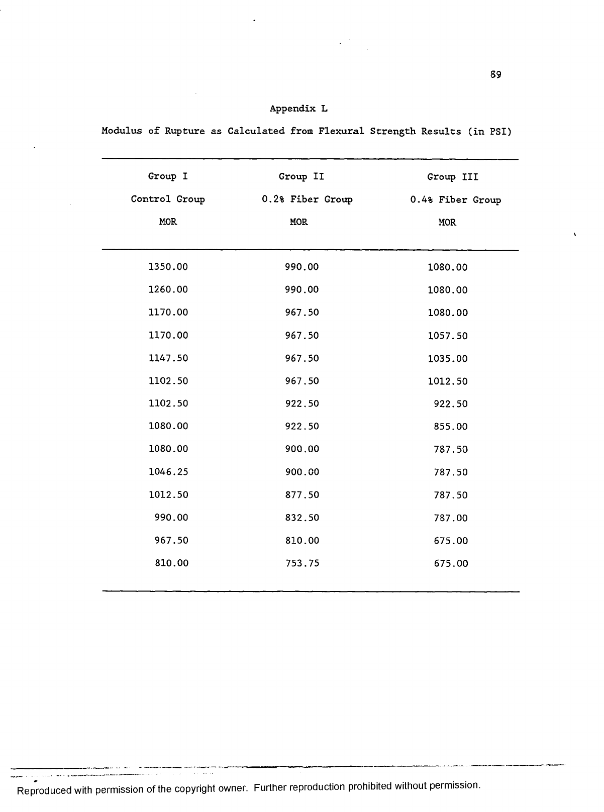
S9
Appendix L
Modulus of Rupture as Calculated from Flexural Strength Results (in PSI)
Group I
Control Group
MOR
Group II
0.2% Fiber Group
MOR
Group III
0.4% Fiber Group
MOR
1350.00 990.00
1080.00
1260.00 990.00
1080.00
1170.00 967.50
1080.00
1170.00
967.50
1057.50
1147.50 967.50
1035.00
1102.50 967.50
1012.50
1102.50 922.50
922.50
1080.00 922.50
855.00
1080.00 900.00
787.50
1046.25 900.00
787.50
1012.50 877.50
787.50
990.00 832.50
787.00
967.50 810.00
675.00
810.00 753.75
675.00
Reproduced with permission of the copyright owner. Further reproduction prohibited without permission.

90
Appendix M
Modulus of Rupture (in PSI) by Batch
Group I
A. Batch
Group II
1
Group III
B . Batch
Group I
2
Group II Group III
1350.00
967.50 1080.00
1260.00 990.00
1080.00
1170.00
967.50
1080.00
1102.50 990.00
1057.50
1170.00 922.50
1035.00
1080.00
967.50
787.50
1147.50
900.00
1012.50
1012.50 967.50
787.50
1102.50 832.50
922.50
990.00 922.50
787.00
1080.00 810.00
855.00
967.50 900.00
675.00
1046.25
753.75
787.50
810.00
877.50
675.00
Reproduced with permission of the copyright owner. Further reproduction prohibited without permission.

91
Appendix N
Frequency Distribution of Modulus of Rupture b y Batch
Range
i = 50 Group I
A. Batch
Group II
1
Group III Group I
B . Batch
Group II
2
Group III
1350-1399 1
1300-1349
1250-1299
1
1200-1249
1150-1199
2
1100-1149 2
1
1050-1099
1
2
1
2
1000-1049
1
1
1
950-999
2
2 4
900-949
2
2
2
850-899
1
1
800-849
2
1
750-799
1 1 3
700-749
650-699
2
N
7
7
7 7 7 7
Reproduced with permission of the copyright owner. Further reproduction prohibited without permission.
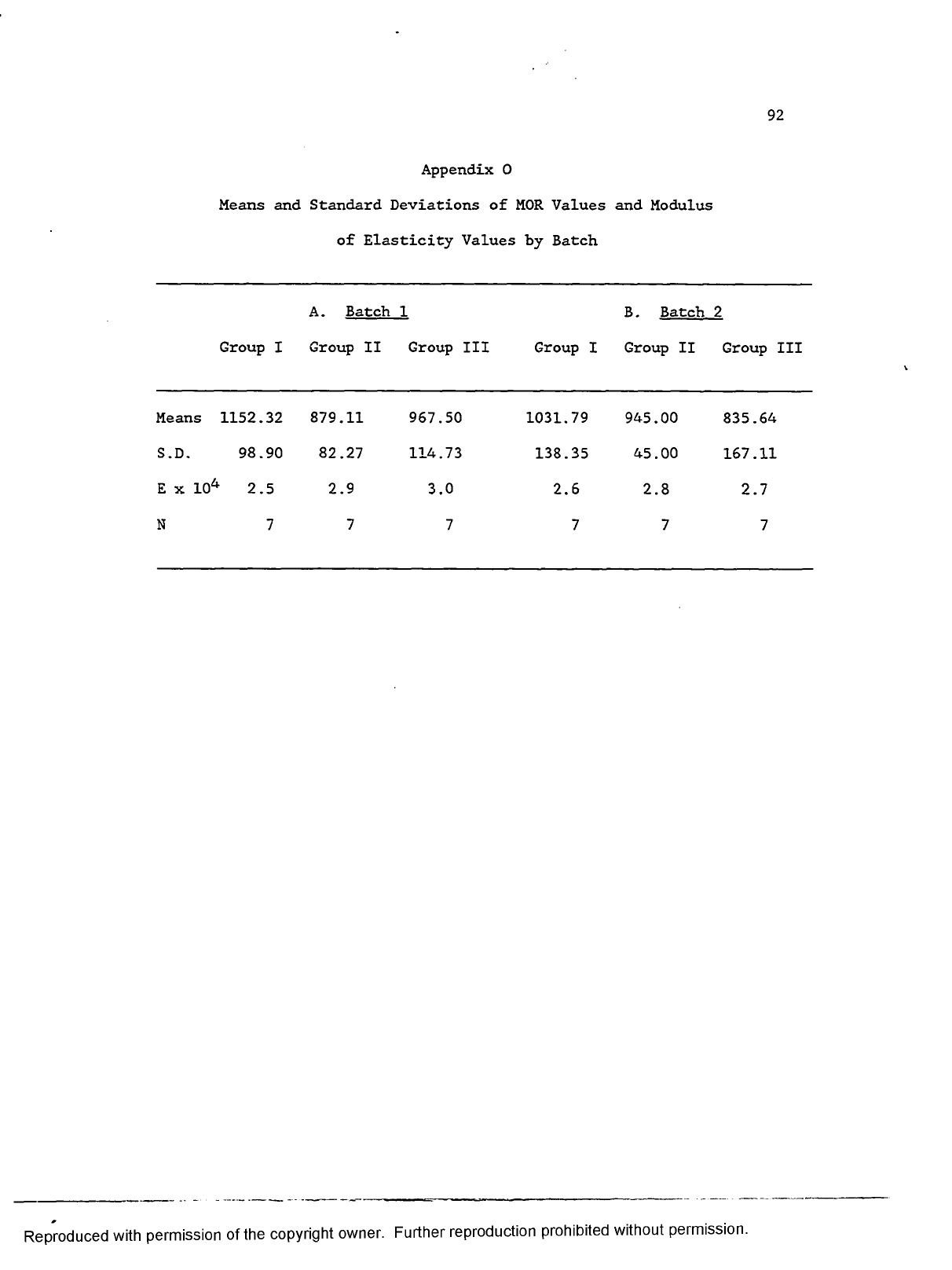
92
Appendix 0
Means and Standard Deviations of MOR Values and Modulus
of Elasticity Values by Batch
Group I
A. Batch
Group II
1
Group III Group I
B . Batch
Group II
2
Group III
Means 1152.32 879.11 967.50
1031.79
945.00 835.64
S.D. 98.90
82.27
114.73
138.35
45.00
167.11
E x 104 2.5 2.9
3.0
2.6
2.8
2.7
N 7 7
7
7 7 7
Reproduced with permission of the copyright owner. Further reproduction prohibited without permission.
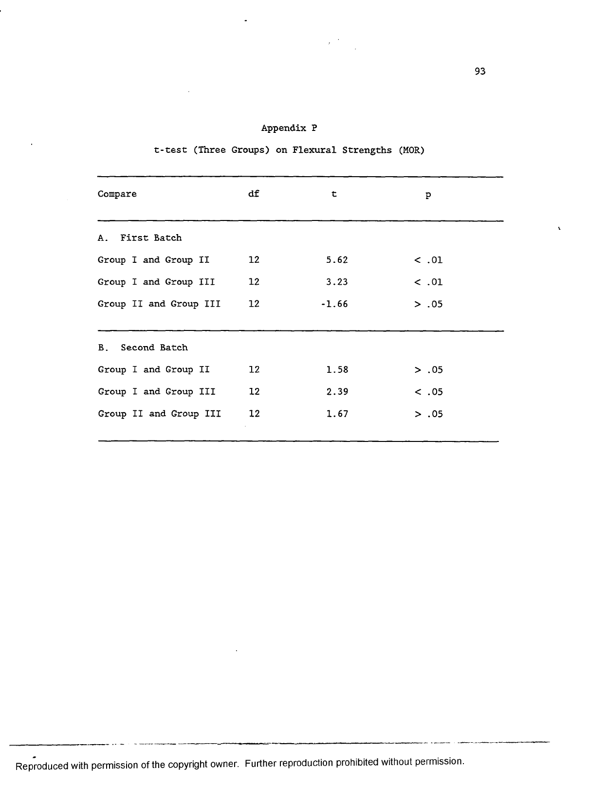
93
Appendix P
t-test (Three Groups) on Flexural Strengths (MOR)
Compare df
t
P
A. First Batch
Group I and Group II 12
5.62 < .01
Group I and Group III
12 3.23
< .01
Group II and Group III
12 -1.66
> .05
B . Second Batch
Group I and Group II
12
1.58
> .05
Group I and Group III
12
2.39 < .05
Group II and Group III
12
1.67
> .05
Reproduced with permission of the copyright owner. Further reproduction prohibited without permission.

94
Appendix Q
One Way ANOVA (Three Groups) on Flexural Strength (MOR)
Source df
Sum
Squares
Variance
Estimate
F
P
A. First Batch
Between-groups 2
272109.38 136054.69
13.74 < .01
Within-groups 18
178272.32 9904.02
Total 20 450381.70
B . Second Batch
Between-groups 2
135246.45 67623.23
4.13 < .05
Within-groups
18 294541.28 16363.40
Total
20
429787.73
Reproduced with permission of the copyright owner. Further reproduction prohibited without permission.

95
Appendix R
Splitting Tensile Strengths of Concrete Cylinders (in PSI)
Group I
Group II
Group III
Control Group
0.2% Fiber Group
0.4% Fiber Group
T
T
T
645.46
680.83
618.93
627.78
645.46
557.04
610.09
610.09
548.20
601.25
584.45
530.52
601.25
583.57
519.02
601.25
583.57
513.72
592.41
574.73
512.83
574.73
565.88
503.99
574.73
565.88
480.12
565.88
565.88
459.78
548.20
548.20
442.98
548.20
539.36
433.25
548.20
539.36
433.25
542.89
503.99
433.25
Reproduced with permission of the copyright owner. Further reproduction prohibited without permission.

96
Appendix S
Splitting Tensile Strength of Concrete Cylinders (in PSI) by Batch
Group I
A. Batch 1
Group II
Group III
Group I
B . Batch 2
Group II
Group III
645.46
645.46
530.52
627.78
680.83
618.93
610.09
583.57
480.12
501.79
610.09
557.04
574.73
574.73
459.78
601.25
584.45
548.20
565.88
565.88
442.98
601.25
583.57
519.02
548.20
548.20
433.25
592.41
565.88
513.72
548.20
539.36
433.25
574.73
565.88
512.83
548.20
503.99
433.25
542.89
539.36
503.99
Reproduced with permission of the copyright owner. Further reproduction prohibited without permission.
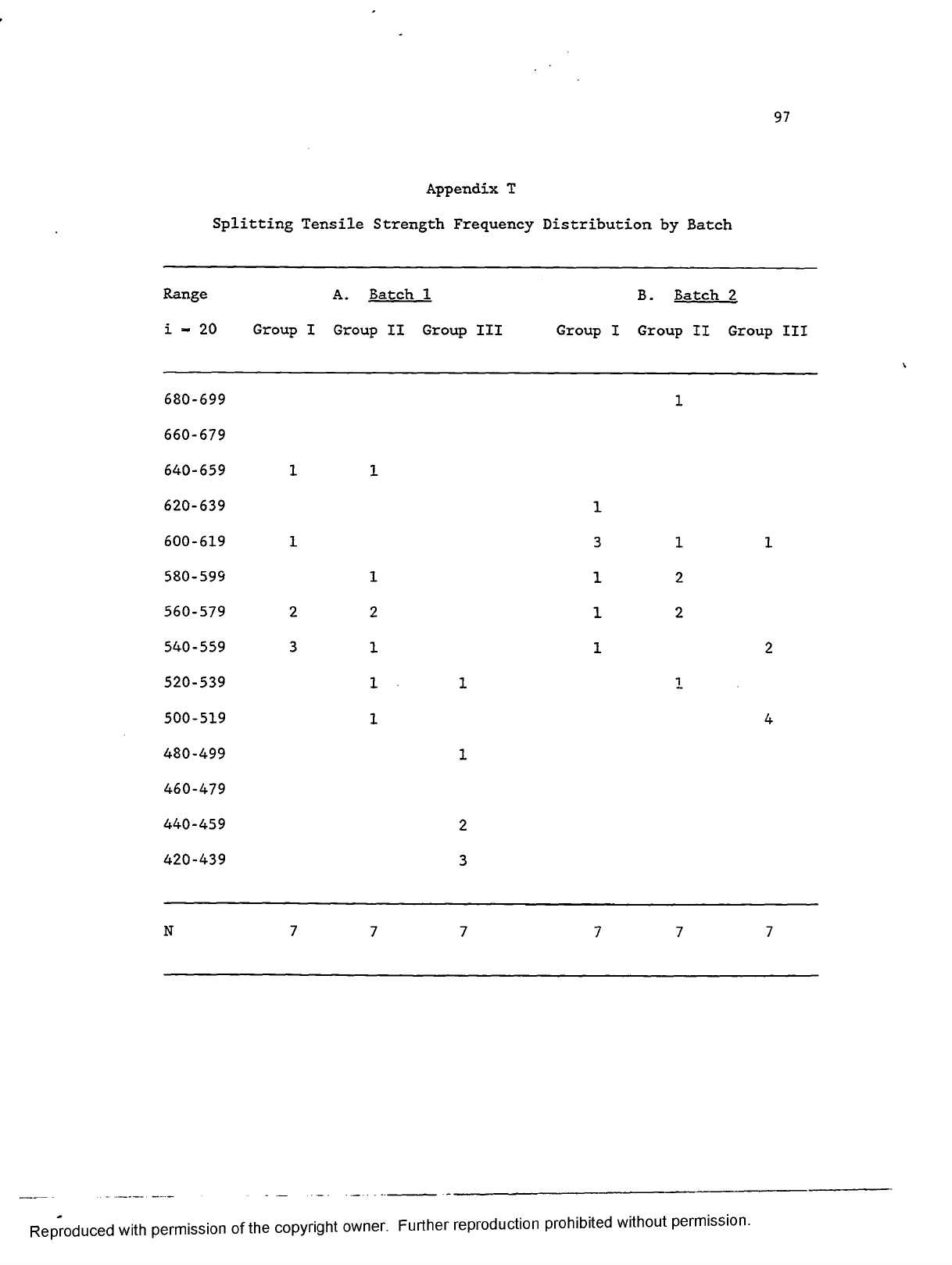
97
Appendix T
Splitting Tensile Strength Frequency Distribution by Batch
Range
i - 20 Group I
A. Batch
Group II
1
Group III
Group I
B . Batch
Group II
2
Group III
680-699
1
660-679
640-659
1
1
620-639
1
600-619
1
3
1 1
580-599
1
1 2
560-579
2
2
1 2
540-559 3
1
1 2
520-539
1 1
i
500-519
1 4
480-499
1
460-479
440-459
2
420-439
3
N
7
7 7
7 7
7
Reproduced with permission of the copyright owner. Further reproduction prohibited without permission.

98
Appendix U
Means and Standard Deviations of Splitting
Tensile Strength Values b y Batch
Group I
A . Batch 1
Group II
Group III
Group I
B . Batch
Group II
2
Group III
Means
577.25 565.88
459.02
591.73 590.01
539.10
S.D. 37.41
43.91
36.07
26.64 45.56
40.31
N
7
7
7
7
7 7
Reproduced with permission of the copyright owner. Further reproduction prohibited without permission.

Appendix V
t-test (Three Groups) on Splitting Tensile Strengths (T)
Compare df
t
P
A. First Batch
Group I and Group II
12
0.52 >.05
Group I and Group III
12
6.02 <.01
Group II and Group III
12 4.98 <.01
B. Second Batch
Group I and Group II
12
0.09 >.05
Group I and Group III
12 2.88 <.05
Group II and Group III
12 2.21 <.05
Reproduced with permission of the copyright owner. Further reproduction prohibited without permission.

100
Appendix W
One W ay ANOVA (Three Groups) on Splitting Tensile Strengths (T)
Sum
Variance
Source
df
Squares Estimate
F
P
A. First Batch
Between-groups
2 59563.50
29781.75
19.30 < .01
Within-groups
18
27776.51 1543.14
Total
20 87340.01
B . Second Batch
Between-groups
2 12514.88 6257.44
4.26
< .05
Within-groups
18
26458.34
1469.91
Total
20
38973.21
Reproduced with permission of the copyright owner. Further reproduction prohibited without permission.
